Acquire Points to edge
Hello
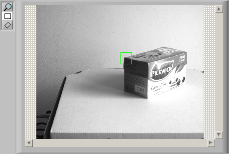
I'm pressing on a tire against a clear plate and looking to see
the contact area that is created and I use Vision Assistant 8.6
to detect the edges of the contact area. However, the only way that
I found to detect the edge of the patch is using the edge
detection function to manually draw lines in the area where the edge
is displayed. Is it possible that I could detect quickly, more than points
as the use of a method of computing any? Thank you very much.
Respectfully,.
Austin Allen
If you use the rake IMAQ function, you will be able to get the coordinates in pixels from the edge you are looking for.
This funstion returns a cluster called research lines where you can find an another cluster called edges containing this information.
Hope this helps
Tags: NI Hardware
Similar Questions
-
Unable to create an access point to edge MyRIO
Hello!
Today I'm trying to follow this white paper (http://zone.ni.com/reference/en-XX/help/373925B-01/myriohelp/myrio_creating_wireless_networks/) to make my MyRIO Board as access point.
I tried with the Interface of MAX but when I tried to access the network settings on the Board of Directors, he doesn't show me an infinite spinner with writing something like "network card search...". "(Translation of my poor french"search of NIC in progress... »). instead of the menu on the first image at this link http://digital.ni.com/public.nsf/allkb/627507F4737474F286257CB4007984C6.
I said I can't do any operation on the interface wlan0 via SSH (no message such as unknown interface wlan0) and the proxy of my company block access to the web configuration of the network card...
But the main problem is this infinite cone. Why?
Please help guys...
Thank you to everyone.
Afghow.
Hi afghow,
The message "no network adapter found" could be the result of:
-Bad IP configuration.
What is your computer IP address and the cRIO one? (you use DHCP or static?)
-A problem with your firewall
Have you tried disabling your firewall in order to access the parameters of myRIO?
Other reasons can be found on the link below:
MAX error on the system remote cRIO "No. Found network adapter"
Kind regards
-
Superposition of the images on the specified point
Hello!
I have 2 pictures with a lot of similarities. I want to layer them on a specified point or edge or a unique feature. Is it possible to choose a point (by hand or by an algorithm) and then find the corresponding (or similar) on the other image? and then superimpose the images according to the corresponding point? Algorithm of the overlay is made, now I need to find matches between the two pictures and then you cover them according to the similarity.
Thank you!
gbbalint
Hello
I modified the labview example. Run it, input two images (left, right), then "load", select the edge KING (see image below) and "search". Then superimpose one image over another with transparent ('overlay'). The code is a bit messy, but you can clean for your project.
You said that the superposition algorithm is done, could you please share it? Maybe your solution is more sophisticated and can help me with another project.
I hope this helps you.
Best regards
K
-
Suspend the edge with game bar animation
Hi there is there a way to pause automatically an animation on board when the user places the project?
There is no communication between edge animate and Captivate built in (like what is possible with widgets). Perhaps by the use of JavaScript, but can not help you. At this point an Edge file animate (oam) is only considered as an animation as an animated GIF, nothing more. It's really a shame because animate can have interactivity as well, perhaps in the future?
-
Edge of page hosted in CMS made simple?
Hi all
I need to do an intro page for a website that is made using CMS.
For testing purposes, I've done that's as simple as possible. I made a project of edge, the 916px width, the height of 550px.
Basically, there is a black background color, and when you hover the mouse on it, it changes to red color.
Now, this works like a charm on my desk. I exported it I got the 4 files, 3 are js and it is an html tag.
This is the html code I have.
<! DOCTYPE html >
< html >
< head >
< meta http-equiv = "Content-Type" content = text/html"; charset = utf-8 ">"
< meta http-equiv = "X-UA-Compatible" content = "IE = Edge" / >
< title > Untitled < /title >
<! - execution of adobe Edge - >
< script type = "text/javascript" charset = "utf - 8" src = "intro_edgePreload.js" > < / script > "."
< style >
.edgeLoad-EDGE-6375286 {visibility: hidden ;}}
< / style >
<! - end of Runtime adobe Edge - >
< / head >
< body style = "margin: 0;" padding: 0; ">
< div id = 'Stage' class = "EDGE-6375286" >
< / div >
< / body >
< / html >
Now, I need to integrate this into a CMS Web site.
I have download 3 js files. I attach them to the top of the page template.
I also add that <!-runtimes Adobe Edge-> part of the head.
In the model, I have a CMS {content} tag and when I go to this page and paste the content, that is, if I understand just the
"<div id="point" class="EDGE-19236779"> " "
< /div >
part, it does not appear on the Web site.
Could someone please explain what I'm doing wrong here?
Nevermind, I fixed.
The js files must be in the root folder.
-
Acquisition of signals according to schedule low external digital input state
Hello
I use DSA devices namely PCI-4472 and PCI-4474 for data acquisition. Our application requires that these councils should acquire data as long as input digital external is in DOWN state that is to say that the device should start acquiring on falling edge and stop on rising acquisition. Unfortunately, I could not find a method to do, which is independent of the number of samples sent to the called function. If I set up the device in this configuration, it starts after the first falling edge and stops on rising edge. But if no. samples to acquire (N = value passed to the called API function) is less then the total no.. samples which are to be acquired (between start and stop say N + X m), the function only returns me the N number of samples during a fall X samples.
Similarly if no. samples between edges of slopes and trigger signal (Y for example) are less value (N) was passed to the API function called, the function return always N = Y + Z, even if we do not require z. samples.
I tried to check this thing in MAX. Can someone help me get around this problem?
Concerning
Mnuet
Sorry about that. I realized while I was writing my response to your original question, you had already posted back. Preston is correct, I was trying to find a way that you could do a digital reading to control the level of the PFI 0 line, but the DSA maps do not have circuits to allow you to make digital reading. The only way you could check the line would be to use a digital I/o card.
Kind regards
Frédéric
-
Help with the NOR-DAQ example Code
Hello. I just started to work with the NI IBS-6211. It's the first ADC I have ever used, so I'm farily to this news. I have some programming knowledge. After a search in the installation files, I found some examples of C Code that runs in the command prompt. I changed an a bit to get it to do what I want. My question is...
Now, I have a few problems. I am trying to print a voltage in the command prompt. I hooked up everything and I used labview to make sure that everything works as it should (it does!). When I compile the C program and the run, instead of returning a voltage that is just acquired points and I really have no idea what are these 'points '.
Here is the main part of the code example:
DAQmxErrChk (DAQmxCreateTask("",&taskHandle));
            DAQmxErrChk (DAQmxCreateAIVoltageChan(taskHandle,"Dev1/ai0","",DAQmx_Val_Cfg_Default,1.0,10.0,DAQmx_Val_Volts,NULL));
            DAQmxErrChk (DAQmxCfgSampClkTiming(taskHandle,"",10000.0,DAQmx_Val_Rising,DAQmx_Val_FiniteSamps,1000));

            /*********************************************/
            // DAQmx Start Code
            /*********************************************/
            DAQmxErrChk (DAQmxStartTask(taskHandle));

            /*********************************************/
            // DAQmx Read Code
            /*********************************************/

            DAQmxErrChk (DAQmxReadAnalogF64(taskHandle,1000,10.0,DAQmx_Val_GroupByChannel,data,1000,&read,NULL));

            printf("Acquired %d points\n",read);

Error:
And then he moves right down to the exit clause. Is there documentation anywhere that tells me what DAQ command should I use to print a voltage continuously updated reading? (As a decimal number, such as 5.21V for example).
Thanks to you all
John
John,
The data acquired by DAQmx are written in the array called "data". The number of points DAQmx wrote in this table is stored in the variable 'read' which was adopted by reference in. To print the values returned, you need to loop through the array of 'data' and print each value. See this help topic for an explanation of DAQmxReadAnalogF64.
Dan
-
Number of events with the DAQ Assistant, offered PFI0, offered Ctr0. Samething?
DAQ USB DAQ Assistant 6009. I plugged a PFI0 (port 29) push button switch and + 5V (port 31). Setup Assistant DAQ ==> Acquire ==> meter entry ==> edge ==> Dev1(USB-6009) - Ctr0 counter ==> a sample on request.
I was offered the Ctr0 and not PFI0 (port 29) selection, so I chose Ctr0. Samething? Will this work with how I wired to the top of my switch?
I count 'digital highs', so wire to 5V and sprayed. Right?
With LV2013 and an acquisition of data connected to the computer, you can do what I did in a vi project and/or a regular, standard vi. Right?
Thank you for your time
dunnor
Hoovahh
My hard wire solution worked will PFI0 and GND. Sorry. I thought I could go back and give congratulations after I tried things. I would like to press the buttons now, but I don't see them.
dunnor
-
The issue of Service of blackBerry Smartphones.
Hello.
Ive had my black Berry "BOLD" for 8 months. I have always noticed that sometimes he says 3G and 4 points on the upper right that im guessing is network service. Sometimes it says edge or EDGE. Is it always switcing back 3 G with 4 points to EDGE and edge. What is depend on the area and what service you get? Also, Ive had a problem with when people call me. They call me and I do not receive calls even when I have the service. I don't know what to do. Im confused on what change settings and things. Please help me. Thank you.
Yes, this applies to the level of service in the region. All the functions on your BlackBerry will perform when you have the BlackBerry symbol, condensed in the upper right corner. Whenever you don't see this symbol, some functions will suffer. A bar with this symbol showing will allow you to make more than five bars of strength without this symbol (which will show only when the 3G is present).

-
Why this line in a mesh have a crease in there?
I have a mesh that I made of an ellipse, and at some point the edge changes direction completely before going to another point (see photo). The score of the right handle does not change the fold at all. Although step as extreme, this also happens to several other points of the mesh.

How can I fix? Ask if you need more info or pictures; I'm new to illustrator and don't know what info is relevant.
Because it has a hidden anchor "helper." Click on the 'more or less of the pen tool' and the hidden points will appear. Then you can remove them or change them as standard Bézier points.
-
Make a version vector of this image of "cloud / flaky."
Hello master Illustrator & end users
I have a small picture of a cloud / flaky I want to vectorize and need help on how to get the best work is done. Here's the image in question.

I tried the trace Illustrator and paint and or give me the sharpness and tightness I'm after. I also tried to use the tool star shape and modify the points rounded-edge, but it is very hard to get the symmetric roundness as it appears. Other means that could be better to get the form are appreciated.
Thanks in advance,
desioner
Even easier with a control much more...
- Draw a circle.
- With the circle selected, choose effect > warp & Transform > Zig Zag
- Set the size of Zig Zag to 0, select Relative, crests set at about 4 (you can change that more in a minute), select smooth down and click OK
- Now choose effect > warp & Transform > Pucker & bloat
- Pucker & bloat to 7%, click OK.
You should now be very, very close.
To adjust the amount of bumps and their width/count, click Zig Zag again in the appearance Panel, and then play with the ridges by Segement slider. To adjust the height or size of the bumps real, click the Pucker & bloat in the appearance Panel, and move the slider.

This method allows you to completely change the bumps without having to adjust an ellipse or any other primary object.
Here is a quick movie showing it in action: film Puff (~ 500 k)
-
ORA-13033 ORA-06512 at 11.1.0.7
I have a single shape that seems to cause of ORA-13033 11.1.0.7 but not 11.1.0.6. Wondering if I am missing something stupid, or if someone else has experienced this problem. I did a quick search of positions, but found nothing. It could also be that space has a problem on the 11.1.0.7 server...
Thank you
-on 11.1.0.7
SQL > drop index foo_spatial_index;
The index is deleted.
SQL > drop table foo;
Deleted table.
SQL > delete from user_sdo_geom_metadata where table_name = 'FOO ';
1 line removal.
SQL >
SQL > create table foo (shape sdo_geometry);
Table created.
SQL > insert into foo values (SDO_GEOMETRY (3002, NULL, NULL, SDO_ELEM_INFO_ARRAY (1, 4, 1, 1, 2, 2), SDO_ORDINATE_ARRAY (484893.192, 1845442.68))
0, 484881.786, 1845444.7,.5, 484871.639, 1845450.28, 1)));
1 line of creation.
SQL > insert into user_sdo_geom_metadata values ("FOO", "SHAPE", SDO_DIM_ARRAY (SDO_DIM_ELEMENT(, 484719.102, 484904.266,.0000005), SDO_DI
(M_ELEMENT(null, 1845366.11, 1845513.86,.0000005), SDO_DIM_ELEMENT (NULL, 0, 5368.70912,.0000005)), null);
1 line of creation.
SQL > create index foo_spatial_index on foo (shape) indextype is mdsys.spatial_index;
create index foo_spatial_index on foo (shape) indextype is mdsys.spatial_index
*
ERROR on line 1:
ORA-29855: an error has occurred in the execution of routine ODCIINDEXCREATE
ORA-13249: internal error in the Spatial index: [mdidxrbd]
ORA-13249: error in the Spatial index: index build failed
ORA-13249: error in the spatial index: [mdrcrtxfergm]
ORA-13249: error in the spatial index: [mdpridxtxfergm]
ORA-13200: internal error [ROWID:AAFV8VAAHAAAGUtAAA] in spatial indexing.
ORA-13206: [] internal error creating the spatial index
ORA-13033: invalid data in the SDO_ELEM_INFO_ARRAY in the SDO_GEOMETRY object
ORA-06512: at the 'MDSYS. SDO_INDEX_METHOD_10I', line 10
-on a different 11.1.0.6
SQL > drop index foo_spatial_index;
Drop index foo_spatial_index
*
ERROR on line 1:
ORA-01418: specified index does not exist
SQL > drop table foo;
drop table foo
*
ERROR on line 1:
ORA-00942: table or view does not exist
SQL > delete from user_sdo_geom_metadata where table_name = 'FOO ';
0 rows deleted.
SQL >
SQL > create table foo (shape sdo_geometry);
Table created.
SQL > insert into foo values (SDO_GEOMETRY (3002, NULL, NULL, SDO_ELEM_INFO_ARRAY (1, 4, 1, 1, 2, 2), SDO_ORDINATE_ARRAY (484893.192, 1845442.68))
0, 484881.786, 1845444.7,.5, 484871.639, 1845450.28, 1)));
1 line of creation.
SQL > insert into user_sdo_geom_metadata values ("FOO", "SHAPE", SDO_DIM_ARRAY (SDO_DIM_ELEMENT(, 484719.102, 484904.266,.0000005), SDO_DI
(M_ELEMENT(null, 1845366.11, 1845513.86,.0000005), SDO_DIM_ELEMENT (NULL, 0, 5368.70912,.0000005)), null);
1 line of creation.
SQL > create index foo_spatial_index on foo (shape) indextype is mdsys.spatial_index;
The index is created.There are a number of things wrong with your geometry.
The record says that for compound geometries (sdo_etype = 4) SDO_INTERPRETATION (in this case with sdo_etype = 4) gives the number of subitems. This should be more then 1 large:
http://download.Oracle.com/docs/CD/B28359_01/AppDev.111/b28400/sdo_objrelschema.htm#BGHDGCCE
4
n > 1
Compound line string with some vertices connected by straight segments and some by circular arcs. The value n in the interpretation column specifies the number of contiguous subelements that make up the line string.
The triplets following n in the Ansdo_elem_info table describe each of these sub-elements. Subitems cannot SDO_ETYPE 2. The last point of a subelement is the first point of the next subelement, and should not be repeated.
In your case, you will either need a string of single line that makes the first triplet even unnecessary or incorrect in the Ansdo_elem_info, or you are missing a third triplet in the Ansdo_elem_info.
You should always validate your geometry first, if you do this also on your 11.1.0.6 version you will get:
SDO_GEOM. VALIDATE_GEOMETRY_WITH_CONTEXT
---------------------------------------
54506 point: 0, Edge: 2,.
ORA-54506: compound curve not supported for 3D geometries
Cause: The 3D geometry contained one or more compound curves, which are not
support for 3D geometries.
Action: Remove all the curves of geometry.As you can see also compound curveare not supported in 3D geometries.
IF it is not a compound (with SDO_ELEM_INFO_ARRAY = (1,2,2), you will see that this geometry will validate.
Looks like the validation could be integrated now in creating indexes in 11.1.0.7.
Published by: lucvanlinden on March 20, 2009 09:07
-
Need help, definition 3d solid - stuck on the roof
I'm trying to define a 3d solid to represent a simple building with a roof, as shown in this image. I'm working through the examples of the [space Developer Guide | http://download.oracle.com/docs/cd/B28359_01/appdev.111/b28400/sdo_objrelschema.htm#CBBGAJFH]
] .
My plan is to define the main part of the building in the form of solid with 6 surfaces. This part works fine. Then, I want to define the structure of the roof in the form of solid with 5 surfaces. Then, I'll use SDO_UTIL. ADDED to put it together.
I'm stuck on the roof!
There are 5 areas:
-the base of the roof (A)
-the first slope of roof (B)
-the first sprocket (C)
-the second slope of the roof (D)
-the second gear (E)
See image here.
So I defined as follows:
But when I validate I get:INSERT INTO geometry_examples (name, geom) VALUES ( 'Roof of house', SDO_GEOMETRY ( 3008, -- SDO_GTYPE set to 3008 for a Simple Solid NULL, -- No coordinate system NULL, -- No data in SDO_POINT attribute SDO_ELEM_INFO_ARRAY( 1, 1007, 1, -- Descriptor for a single solid 1, 1006, 5, -- 5 composite surface elements -- element triplets to follow 1, 1003, 1, -- bottom of the roof - i.e. the flat bit (rectangle) 6, 1003, 1, -- east roof slope (rectangle) 11,1003, 1, -- north gable end (triangle) 15,1003, 1, -- west roof slope (rectangle) 20,1003, 1 -- north gable end (triangle) ), SDO_ORDINATE_ARRAY ( 4,0,2, -- bottom of the roof (rectangle) Surface A 4,2,2, 2,2,2, 2,0,2, 4,0,2, 4,0,2, -- east roof slope (rectangle) Surface B 4,2,2, 3,2,4, 3,0,4, 4,0,2, 4,2,2, -- north gable end (triangle) Surface C 2,2,2, 3,2,4, 4,2,2, 2,2,2, -- west roof slope (rectangle) Surface D 2,0,2, 3,0,4, 3,2,4, 2,2,2, 2,0,2, -- north gable end (triangle) Surface E 4,0,2, 3,0,4, 2,0,2 ) ) );
Any ideas where I'm wrong here?SQL> select SDO_GEOM.VALIDATE_GEOMETRY_WITH_CONTEXT(geom, 0.005) from geometry_examples; SDO_GEOM.VALIDATE_GEOMETRY_WITH_CONTEXT(GEOM,0.005) ------------------------------------------------------------------------------------------------------ 13355 Point:0,Edge:0,Ring:0,Polygon:0,Comp-Surf:0,Solid:0,Multi:1,Hi Reggie.
13355 error means that sdo_ordinate_array is not grouped by number of dimensions grouped due to bad indices in your elem_info_array. I tried the following:SDO_GEOMETRY
(
3008,-SDO_GTYPE 3008 for a Simple solid value
NULL,-no mark
NULL, no data in the attribute SDO_POINT_TYPE
() SDO_ELEM_INFO_ARRAY
1, 1007, 1,-descriptor for a single solid
1, 1006, 5,--5 composite surface elements
-Triple element to follow
1, 1003, 1, - the bottom of the roof - i.e. the flat Wick (rectangle)
16, 1003, 1,-the slope of the roof is (rectangle)
31,1003, 1,-North gable (triangle)
43,1003, 1,-the slope of the roof (rectangle) West
58,1003, 1 - North gable (triangle)
),
SDO_ORDINATE_ARRAY
(
4,0,2,--Bas of the Surface (rectangle) roof has
4.2.2,
2,2,2,
2,0,2,
4,0,2,
4,0,2,--La slope of the roof (rectangle) is Surface B
4.2.2,
3,2,4,
3,0,4,
4,0,2,
North 4,2,2,--Pignon (triangle) Surface C
2,2,2,
3,2,4,
4.2.2,
2,2,2,--La (rectangle) roof pitch Surface D West
2,0,2,
3,0,4,
3,2,4,
2,2,2,
North 2,0,2,--Pignon (triangle) Surface E
4,0,2,
3,0,4,
2,0,2
)
)I was then 54502 which means that the solid is not closed. The solid must be closed volume.
You can set this geometry as a collection as follows:SDO_GEOMETRY
(
3004,-SDO_GTYPE 3008 for a Simple solid value
NULL,-no mark
NULL, no data in the attribute SDO_POINT_TYPE
() SDO_ELEM_INFO_ARRAY
-1, 1007, 1,-descriptor for a single solid
1, 1006, 5,--5 composite surface elements
-Triple element to follow
1, 1003, 1, - the bottom of the roof - i.e. the flat Wick (rectangle)
16, 1003, 1,-the slope of the roof is (rectangle)
31,1003, 1,-North gable (triangle)
43,1003, 1,-the slope of the roof (rectangle) West
58,1003, 1 - North gable (triangle)
),
SDO_ORDINATE_ARRAY
(
4,0,2,--Bas of the Surface (rectangle) roof has
4.2.2,
2,2,2,
2,0,2,
4,0,2,
4,0,2,--La slope of the roof (rectangle) is Surface B
4.2.2,
3,2,4,
3,0,4,
4,0,2,
North 4,2,2,--Pignon (triangle) Surface C
2,2,2,
3,2,4,
4.2.2,
2,2,2,--La (rectangle) roof pitch Surface D West
2,0,2,
3,0,4,
3,2,4,
2,2,2,
North 2,0,2,--Pignon (triangle) Surface E
4,0,2,
3,0,4,
2,0,2
)
)Can I get 54518 which means shared composite surface edges are not oriented correctly.
Finally, I've also got rid of 1006 to elem_info_array to get rid of this last error and:SDO_GEOMETRY
(
3004,-SDO_GTYPE 3008 for a Simple solid value
NULL,-no mark
NULL, no data in the attribute SDO_POINT_TYPE
() SDO_ELEM_INFO_ARRAY
-1, 1007, 1,-descriptor for a single solid
-1, 1006, 5,--5 composite surface elements
-Triple element to follow
1, 1003, 1, - the bottom of the roof - i.e. the flat Wick (rectangle)
16, 1003, 1,-the slope of the roof is (rectangle)
31,1003, 1,-North gable (triangle)
43,1003, 1,-the slope of the roof (rectangle) West
58,1003, 1 - North gable (triangle)
),
SDO_ORDINATE_ARRAY
(
4,0,2,--Bas of the Surface (rectangle) roof has
4.2.2,
2,2,2,
2,0,2,
4,0,2,
4,0,2,--La slope of the roof (rectangle) is Surface B
4.2.2,
3,2,4,
3,0,4,
4,0,2,
North 4,2,2,--Pignon (triangle) Surface C
2,2,2,
3,2,4,
4.2.2,
2,2,2,--La (rectangle) roof pitch Surface D West
2,0,2,
3,0,4,
3,2,4,
2,2,2,
North 2,0,2,--Pignon (triangle) Surface E
4,0,2,
3,0,4,
2,0,2
)
)It validates well.
There are a few rules of solids that we listed in the Handbook of spatial use and book of Pro Oracle Spatial 11g.
I can also recommend you to read the next book to understand the geometry in Oracle Spatial 3D validation rules:
"On the three-dimensional geometries valid and invalid. If you can't find it, please let us know.If you need to qualify this 3008 geometry, you will need to correct the direction and close the volume of solid geometry. It is also a need to define a solid simple i.e. gtype 3008 with etype from 1007 and which is not cut in two independent volumes. If you define two or more solids, you can use the collection, composite solid or multi solid rules.
Please let us know if you have any other questions.
Beautiful House :)
Best regards
Baris -
I would like to be able to scroll using the gesture control. I think I've been using sound, but it now seems to be not not available.
Scrolling by pointing at the helm of the edge is a pain!Gestures are a feature of your operating system. Check your operating system settings.
TB - 38, 3 Win10-PC
-
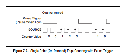
How to generate a single Point (On-Demand) edge counting with relaxing break
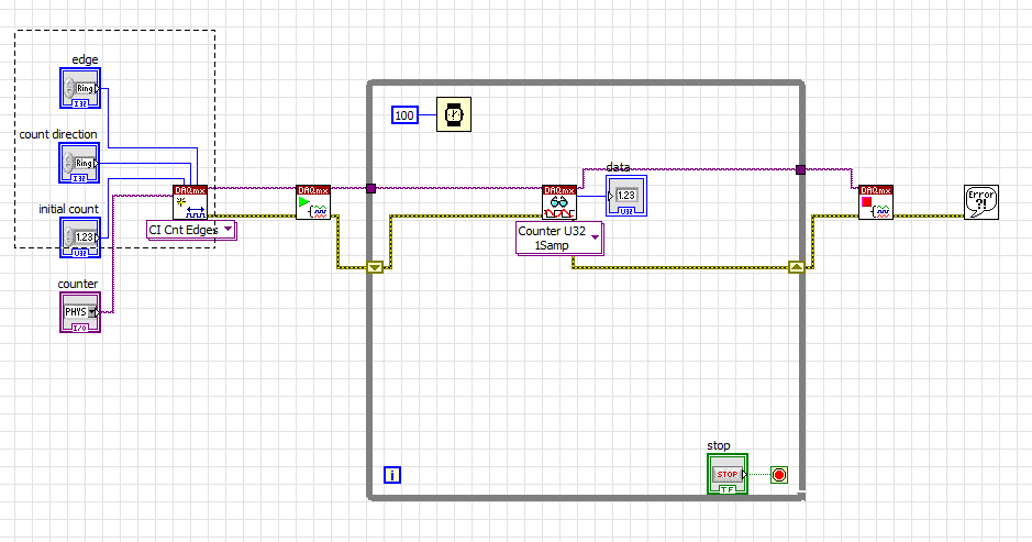
I have problem when creating a Labview program to generate a single Point (On-Demand) edge counting with relaxing break illustrated in FIGURE 1 below. I only know how to build counter edge without relaxing break and my program is illustrated in FIG. 2 and gaskets also. Should what changes I make on my program? The DAQ card that I use is 6259 PCI/USB.
FIG1. Single edge counting with break Point (on request)
Fig.2 my program to generate the edge without relaxing break
It is resolved


Maybe you are looking for
-
How to detect the data type is?
Hello! I built a function of VI. But I want to make it safe - function could detect what type of data is connected to the inputs and only allow certain types of data cabling. How can I do this? Thank you
-
Error code 80070057 KB963678 and KB963669 update installation microsoft office help
Hello I have install all other updates successfully, these 2 have 963678 KB and KB963669 error code. Can you please help. Thank you
-
Error 1719 when trying to install new programs, etc...
Each time, for the last 7-10 days, I try to install anything as this is to say.-Adobe Reader / Google Earth / Microsoft Silverlight / etc... I get an "Error 1719' and the text on an installation problem. In the week before that, I installed IE8 and 2
-
When I sit in a dark room with my laptop, the brightness is too much for me. How can I dim it down, I can't find a setting or a button to do it.
-
Microsoft Windows Unified Data Storage Server 2003 (PowerVault NX) 1950 drivers
Hello I'm looking for drivers for the above system, but seem to be going round in circles on the usual site of dell support. OMSA tells me that the driver of the minimum I need is 2.24.00.32 but I can't seem to find this I would be very grateful if a