Acquiring temp with NI 9214 using labview fpga
Hello
I'm a student, very new to labview and data acquisition. I had problems with a thermocouple type T of wiring to a NI 9214 module and writing a program labview FPGA to acquire temperatures. I've been struggling with this and for a long time to research on the web without success.
Please find attached the code that I work with. I was told to use the value obtained from the CJC and converted using the formula I found here ( http://zone.ni.com/reference/en-XX/help/370984T-01/criodevicehelp/9214_converting/ ) and arrays of conductor thermocouple type T to find the temperature, but I didn't get anything that makes sense.
Please can someone help me?
Jeremiah
Hi Jeremiah,.
You use this 9214 in cRIO chassis? If Yes, which model?
Regarding the conversion of the data, you have to take care to recover the data from the side host (you'll need a separate VI) and taking care of converting it. When you mention that you don't get what makes sense, what exactly read / do you expect?
I strongly suggest you open and tinkering with the example of the host/FPGA shipping screw to the 9214 (NI 9214 Get Started.lvproj, found in the program NIUninstaller Instruments\LabVIEW 2013\examples\CompactRIO\Module Specific\NI 9214\NI 9214 Getting Started). It should allow you to have a good knowledge in understanding the relationship between the host and the screw of the FPGA.
I hope this helps!
Tags: NI Software
Similar Questions
-
Simulate the sine wave using LabVIEW FPGA with NOR-myRIO and display in real time
Hello
I'm relatively new to LabVIEW FPGA. I am trying to test (and later apply) controllers high speed on myRIO.
At this point, I'm trying to simulate the sine wave from 1 to 10 kHz using Sinewave generator VI express. I also intend to display the sine wave on the time real (RT) using FIFO. However, I had a bit of trouble to understaing various synchronization parameters.
1. how to encode information about the sampling frequency generating sine wave? (The side FPGA vi requires only the frequency of the signal and possibly phase and does not rate update lines)
2. how to estimate the number of items in a FIFO? (that is, the relationship between the rate of updates to loop (RT), the signal frequency, sampling frequency and the number of items in the FIFO)
It would be great if we could share a very simple program (side host and target) that did something similar.
Thank you
MILIN
Milot,
I think the problem is the type of data in your FIFO. Your FIFO is configured to use a data type of I16. The problem is the number, it displays only ever will be-1, 0 or 1. To resolve this problem, you must send the sine wave as a fixed point data and convert it to a double on the side of the RT. This should significantly improve your resolution.
-
Deal with failure when using LabVIEW 2011 and DSC MODBUS communication
I'm currently reading from operating records a PLC with MODBUS/TCP. I confirmed that the PLC will update the values and in response to a MODBUS communication correctly by using a third-party program called Modbus Poll. However, when I try to query the PLC using the LabVIEW shared variable engine, I am unable to read the values of the same addresses that I consult with Modbus Poll.
My installation is simply to a PC directly connected to the controller via Ethernet without a router between the two. I'm using LabVIEW 2011 SP1 with the DSC module.
I opened the Manager of distributed systems OR to display the State of all variables in the Modbus Library that I created, and I noticed that the ILO CommFail permanently the value 'true '. All other variables with a 'read' access mode signal "failure of process". I tried to restart the process and stop and start the local variable engine without success. I also restarted my computer several times to see if any services did not exist, but this does not appear to have solved the problem.
Finally, I resorted to listening to communications on the network card I have the PLC connected via Ethernet using Wireshark and found that while Modbus Poll communicates with PLC, number of MODBUS and TCP packet is sent and received. However, when using only LabVIEW or the DSM OR communicate with the controller, there don't seem to be any communication on the network card.
Something that may be interesting to note is that I could communicate with the PLC and to read values with the DSM just once, when I understood everything first what address I should be reading of. All of this has stopped working shortly after. Prior to this, 'CommFail' was not generally set to 'true' with my current setup. Thinking it was my firewall, I have since disabled my firewall, but this seems to have had no effect on the problem either.
Any help on this would be appreciated.
So, I thought about it. It turns out that the IP address of the server i/o MODBUS must be set to the address of the MODBUS slave, not the local computer. The address of the i/o MODBUS server is defined by the navigation in the Explorer window projects, expanding the variable engine shared library for MODBUS and right click on the server MODBUS (for example Modbus1) item and select Properties.
In addition, the addresses seem to be shifted by + 1.
Thanks for the tip so.
-
How to acquire the data of hp34970a using labview
Hello
I'm new to LABVIEW. I saw an example of vi on agilent 34970 ez scan. Can I add or make changes to State example to run my vi? When I run the example of the instrument, it's stopping and takin juz one analysis. Wat shud I do to run it for a while? where shud I make the changes to the trigger and scanning?
can someone help me?
Yes, if you have no loop, the code runs only once. Have you looked at the example in the thread, I gave?
You can take the tutorials.
-
Integration of IP node evil in LabVIEW FPGA
Hi all
I am having trouble with the integration of LabVIEW FPGA IP option and was hoping someone could shed some light here.
I use a simple VHDL code for a bit, 2: 1 MUX in order to familiarize themselves with the integration of IP for the LabVIEW FPGA.
In the IP properties of the context node, the syntax checking integration says:
ERROR: HDLParsers:813 - "C:/NIFPGA/iptemp/ipin482231194540D2B0CC68A8AF0F43AAED/TwoToOneOneBitMux.vhd", line 15. Enumerated value U is absent from the selection.
but I'm still able to compile. Once the node is made and connected, I get the arrow to run the VI but when I do, I get a build errors in Code Pop up that says:
The selected object is only supported inside the single-cycle Timed loop.
Place a single cycle timed loop around the object.
The selected object in question is my IP integration node.
I add a loop timed to the node, but even if I am able to run the VI, it nothing happens. the output does not illuminate regardless of the configuration.
I would say that I tried everything, but I can't imagine would be the problem might be at this point given that everything compiles and the code is so simple.
I have attached the VI both VHDL code. Please let me know if any problems occur following different boards of the FPGA.
Would be really grateful for the help,
Yusif Nurizade
Hey, Yusif,.
Looks that you enter in the loop timed Cycle and never, leave while the indicator of Output never actually is updated. Try a real constant of wiring to the break of the SCTL condition. Otherwise, you could spend all controls/indicators inside the SCTL and get rid of the outside while loop. You can race in the calendar of meeting bad in larger designs without pipeling or by optimizing the code if you take this approach, however.
-
I have a disc that rotates at about 3000 rpm. Whenever this disc rotates one revolution, it generates a pulse. I want to take this impulse 100 samples (each 3.6 deg). I want to do this I want to divide the subsidiary pulse in 100 pulses, the time between each of these subsidiary pulses (samples) is constant, however, the speed of the drive can vary from 3 or 4 RPM. This means I can't say exactly how long a disc rotation will take. This is why I can't have a fixed sample rate because in order to get the same time difference between each auxiliary pulse, I need to dynamically change the number of samples to be taken depending on the speed of rotation of the disc. I want to acquire data of four sensors of pressure OR-9237, cRIO-9114. I'm using LabView FPGA.
Any help, direction, or other ways you would to do this will be much appreciated. I'm new fairy on LabView
 . I also hope that I have post in the right section.
-
How to use bidirectional I/O in the CLIP of LabVIEW FPGA?
How to use or define two-way i/o for CLIP with LabVIEW FPGA? I want to use 1-wire communication inside the kernel CLIP, the function will be implemented to read and write as I/O inside the CLAMP.
The XML Generator (CXG) 1.1.0 ELEMENT does not support.
Thank you
Supawat
Work after separate IB pin (bidirectional) at the entrance and exit. Thank you.
-
NEITHER 9512 with Labview FPGA Interface
Is it possible to use the NI 9512 stepper with Labview FPGA interface drive unit or is it only possible to use it with the interface of scanning? When I try to add the module to a FPGA target, I get an error telling me that Labview FPGA does not support this module with the latest version of NOR-RIO, but I have the latest version of OR-installed RIO.
Hi Checkit,
You're right - the 9512 cannot currently be used in FPGA. There is an error in the documentation. The 9514 and 9516 can, however.
-
reading photoplethysmograph waveform with serial port on PC using Labview
Hello world
I'm gaining time real Photoplethysmography waveform of serial port using Labview.I have managed to acquire data from serial port by using the following features:
-Baud rate: 38400
-data bits: 8
-stopbit: 1
-No parity bit
-Time delay before reading the serial port: 10 ms (according to what was written in the manual that every 10 ms there is a frame in serial port)
After the reading string will be converted to byte array to be able to extract the bytes associated with waveform (1 & 2 bytes in a frame) even for SOP2 (6 & 7)
(what is read in serial port is in decimal and must be converted to hexadecimal based on what made the software of prodeuct for some result.that in the waveform properties, I chose the hexadecimal representation)
Then, as mentioned in the manual, I associate these two values to draw the waveform.
Although I used the filter band digital waveform of pulse but not significant pass that was seen (cutofffrequeny:10 high low cut-off frequency: 0.5).
I have attached my program and result in front of Panel and manual for the sensor. The result is still far from what is supposed to be. I was wondering if you could help me and let me know your opinion on the program and the protocol used. I have to get the result as soon as possible. Please let me know if you need more information.
Kind regards
-
Using an FPGA as a stand-alone system to run labview 2012
Hello
I have a request for my main project which is built using Labview 2012 and I want to transfer to a FPGA as it becomes a stand-alone system with no attached PC. I saw that labview for this but I do not know what card FPGA and the labview libraries are able to do this, and what is the mechanism to do this.
Software details: LabVIEW Professional Development System version 2012
Operating system: Windows 10T2dei wrote:
What about Xillinx Zedboard? Y at - it approach to transfer of LabVIEW code directly without the conversion, in the zedboard?
N ° Code LabVIEW FPGA only works on FPGA boards OR. If you give us a better idea of what your project and what you want, we could probably give you a better recommendation.
Furthermore, since this is for reasons of the student, give your representative OR a call and maybe they can cut you a deal on a Board sbRIO.
-
Model a block synchronous dual-port RAM with LabVIEW FPGA
This question caught my attention recently.
I am trying to model a particular design element called "RAMB4_S8_S8" with the LabVIEW FPGA module. This element is a block synchronous dual-port RAM allowing simultaneous access to two ports independently from each other. That being said, a port can perform read/write operation to this RAM while at the same time, the other port might be able to do the same thing. There are two opportunities of possible port conflict, however. The first is when both ports are trying to write to the same memory cell. The other scenario is when a port writes in a cell memory while at the same time the other port reads from it. Other than that, everything should be a legitimate operation.
In order to reproduce this I select memory block that is integrated into my FPGA target. An interface is configured to be the playback mode, and the other is set to write fashion. For the option of arbitration, I let the two interfaces to be "arbitrate if several applicants only. Then I got a compiler error when I tried to run my FPGA code for this model in a SCTL. The error message is something like "several objects to request access to a resource through a resource configured with option interface" arbitrate if several applicants only ", which is supported only in the single-cycle Timed loop if there is only a single applicant by interface.
This error goes away if I replace the SCTL with a simple while loop, but not what I would like to implement. So I wonder if there is a better solution to this problem, or is it just the limitation of the LabVIEW FPGA module.
Thank you.
Yes, you can use a form of conduct to perform the operations you want in the generations clock cycles, but all the code is inside a single SCTL. Basically, read the first address and storing in a register in a single cycle and then read the second address in the second clock cycle. This would allow you to two readings of valid memory every clock cycle 2. I have included a crude extract to illustrate the concept. The case selectors are identical with address A being connected to the memory in the true case, B in the case of fake address. Your biggest model memory dual port will be intact, but it will operate at 1/2 rate.
Take a look at the white paper that provides more details on the construction of memory:
Data on a target FPGAS (FPGA Module)
The ball on the memory block indicates that memory block double port cannot be applied in a configuration of reading, which is a double ROM. access read/write port must be imitated with custom code.
-
HELP - FPGA SPARTAN 3E-100 CP132 WORKS WITH LABVIEW FPGA?
HI EVERYONE, GET ON IM TRYING TO USE MY FPGA WITH LABVIEW, BUT I DO KNOW THAT IF ITS COMPATIBLE, I INSTALLED THE DRIVERS, MODULE FPGA AND LABVIEW 2012, IM USING WINDOWS 7 32 BIT, AND AFTER I COMPILED ITS SAYS:
LabVIEW FPGA called another software component, and the component returned the following error:
Error code:-310601
NOR-COBS: Impossible to detect the communication cable.
Check the communication cable is plugged into your computer and your target. Also, verify that the proper drivers are installed.Thank you.
=)
Hi dvaldez2.
LabVIEW FPGA offers no support for any material to third parties, other than the 3rd Spartan XUP Starter Kit. These are probably the drivers you downloaded.
http://digital.NI.com/express.nsf/bycode/Spartan3E?OpenDocument&lang=en&node=seminar_US
However, this driver supports only the Starter Kit Board itself (http://www.digilentinc.com/Products/Detail.cfm?NavPath=2, 400, 790 & Prod = S3EBOARD). You may not use the driver with any other Xilinx FPGAS.
I hope this helps.
-
LabVIEW FPGA failure with compiler Xlinx?
I'm in LabVIEW FPGA 8.6 with NOR-RIO 3.0.1 (to 8.6). When I compile a simple program, I get the notorious:
«Error starting compile step: make sure that a compatible version of Xilinx tools is installed in the location specified in the setup of LabVIEW FPGA.»
I checked the FPGA compile server and I ran the utility fixTlink.VI with no improvement. This produces two identical PC, neither one having a FPGA installed card.
Any ideas?
After further analysis, the problem was to be in our facility in LabVIEW FPGA 8.6. Using the correct Installer of NEITHER solved the problem.
This thread is now resolved.
-
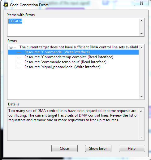
A Labview program with 4 DMA FIFO on FPGA card that can support DMA only 3
Hello
I am a beginner on LabVIEW FPGA, my internship that I work on the previous intern program, there during his internship and he published this program in its report.
On his program, it's that he put 4 DMA FIFO, but supported the FPGA (PXI of NOR-7951) map where we work me and the trainee takes only 3 DMA, so I can't run the program, I have this error:
I wonder if it's a bug or anything else, any ideas?
Sorry to answer the longer end, thank you for your response thank you for your help I could change my program, now the program run with three 3 DMA, I used a table to 2 signals in a single FIFO DMA.
I show the program, that can help someone with the same problem.
-
The project-centric issue of peer to Peer with an external compiler in LabVIEW FPGA
Hi all
FPGA OR Version: 14.0
I have an application developed in LabVIEW interfacing FPGAs developed in LabVIEW FPGA making of peer to peer Communications.
Everything works fine.
I try on the port to Visual Studio 2013 (on the same PC) and am able to communicate with the FPGA very well using the C API.
However, I have a problem now with the help files or the peer supported external compiler peer.
I get these errors:
1. cannot open the file source 'PublicIncludes/nistreamCommon/prefix.h '.
2. impossible opening the file source 'PublicIncludes/nistreamCommon/postfix.h '.
in
c:\Program Files (x 86) \National Instruments\Shared\ExternalCompilerSupport\C\include\nip2p.h
in my project...
I looked in the folder c:\Program Files (x 86) \National Instruments\Shared\ExternalCompilerSupport\C\include\ and the PublicIncludes\nistreamCommon folder does not exist.
What I am doing wrong?
Hello!
It seems that you have worked with another engineer of Applications on this issue. For the love of documents, the nip2p library is not supported in CVI. There has been cases where users were able to get this work to comment on the two header files.
Thank you!
Maybe you are looking for
-
Messages stopped working. End of 2011 macbook pro, Os 10.10.5
Messages has completely stopped working. I have reset my password to icloud and delete old files in the library, but I get a blank screen. I always receive notifications, but can not see them. Cannot access preferences and cannot send a new message.
-
Battery CMOS for PC COMPAQ Presario CQ4010F
Hello. Usually, when I start the PC, I have to reset the time on the internet because the time is wrong and shows of the year in 2009. Then the Control Panel indicates that the CMOS works normally. This leads me to believe that the CMOS battery is dy
-
I recently bought the 4 GB Zotac GTX 970 version. I own the 605-UR1D, with a power of 500w. However, it is said 484 max on feeding. I was running the graphics card very well, until I checked the tempature. Initially, the tempature of graphics card we
-
Blue screen: 0x7e during installation of windows xp
original title: blue screen of death during the installation of windows xp I just bought a motherboard ASUS p5g41t-mlx with a Pentium E5400 2.7 GHz dual core and a hard drive when booting with the windows xp cd in, it goes through the initial configu
-
Windows Vista Ultimate 64-bit will not be in service
Windows Vista Ultimate 64-bit will not be in service. I read the other posts and have followed the suggestions. Windows does not start without failure, or any other option in the F8 boot options. Next step is to create a disk to repair windows, Dell