Delay in acquisition phase data between two lines connected physically on the acquisition of data NI USB-6289
Hello
Currently, we have two signals which are physically and logically linked together on the same line of data acquisition. The first, 'I' and the second signal, 'Q', are both related to "Ai6" (PIN 23) and "Ai GND" (Earth). However, when we probe the two lines coming our function "signal split", I drove Q by about 0.5ms. My question is, if these two lines are actually bound together physically and logically, then why are they phase shifted if they are both the same channel? They should be exact matches. I thought that the phase delay inter-channel occurs only in what concerns channels being read from data acquisition. I have attached a few screenshots as well.
Input signal is 20 kHz. Sampling rate is 40.5 kHz, number of samples/point is 1000.
Thank you.
Best,
Saami
System - Ultrawave Labs engineer
The board you are using is a multiplex. If you create several virtual channels, pointing to the same physical channel, we can enjoy this channel once for each channel. So what's happening essentially is that the physical channel was sampled once for channe 'I', then again for the channel 'Q' with a delay of a few milliseconds in between.
Tags: NI Software
Similar Questions
-
 I'm trying to put a Transition chained between two elements placed one above the other. To the left of the line that she plays in the lower clip and after the line, he played in the clip above. Is that it can be done when the two clips are on the other? I tried and I failed. Help please.
Also how do you call this long line like?
Thank you.
simply put your 'top' clip where it belongs - in the scenario
Select the clip, Option - command - down
the secondary has no replacement for 'tracks '...
-
When I click on to develop, a blue rectangle appears, with two lines connecting opposite angles. I was able to get a picture in this window. Can anyone help?
Hello
Please open Lightroom and click on Preferences.
Once the preferences window opens, go to the performance tab, and please make sure 'Use graphics processor' is unchecked.
After unchecking the option restart Lightroom, and it should deal with the issue.
Please let me know if it helps.
Kind regards
Tanuj
-
I can't find how to change the distance between two lines of text
ureself
ureselfI mean the vertical distance between the two lines with mmmmm
http://codeverge.com/Mozilla.support.Thunderbird/line-spacing-how-to-double-space/1402587
http://forums.mozillazine.org/viewtopic.php?f=39 & t = 403487
-
measurement of phase shift between two periodic signals acquired
Hello
I don't know how to explain my problem, but I'll give it my best shot. I'm two signals from sensors in tension. Two periodic signals have the same frequency, but a different amplitude. Normally they have a difference of phase of 0 or 180 degrees. The thing I have to let labview to check is if the signals are completely in phase or out of phase (180 degrees) completely. I am acquiring the wizard scene DAQ in a while loop. Does anyone have an idea how I can do this?
To summarize: are the two things I need to know
-l'amplitude (maybe just pick max max min distance)
-If both signals are moving in the same direction (when the two signals are in phase) or if they move in the opposite direction (counter phase) - the exact phase angle value is not so important
THX
Thanks for the reply. After a night to think about the problem, I came up with a home-made solution. I used the point by point max and min vi to calculate the distance from crest to crest of my signals. Then, I used the time derivative of point by point to calculate the variation of the signal of the two signals. If the signals are in phase (both are increasing or decreasing at the same time with the other), then the two derivatives have the same sign (accept on the summits, of which I have excluded from the comparison). If the signals are out of phase (when one increases, the other is decreases and vice versa) then the two derivatives are opposite in sign. According to this, I can get all information that I need. If anybody should know a better way to achieve the same result, please say, but to know that it seems to work.
-
Is it possible to route signals of relaxation between two chassis PXI-1002 with the PXI-8335?
Hello
as the subject says, I am interested in the delivery of a signal to trigger between two chassis PXI-1002. At present, these two chassis are connected by a MXI - 3 system using maps PXI-8335. The software is Labview 2010 sp1 and 380 NIScope drivers.
We want to keep (a PXI-5122 by chassis) scanners supply separated due to the requirements of our measure! The chassis are connected via cable to fiber optic. This explains why I can not just use the shutter release in Star, or connect via 'Trigger' or 'clk' cards (the inputs / outputs to the front of the cards).
I found a few examples, but they seem to all be designed for use with a chassis only, I'll call later to the examples that inspired me to this point. Each guide explaining the synchronization of several chassis systems seems to use another material or VI is not accesible to me. This makes me wonder if my hardware has the capacibilities I need.
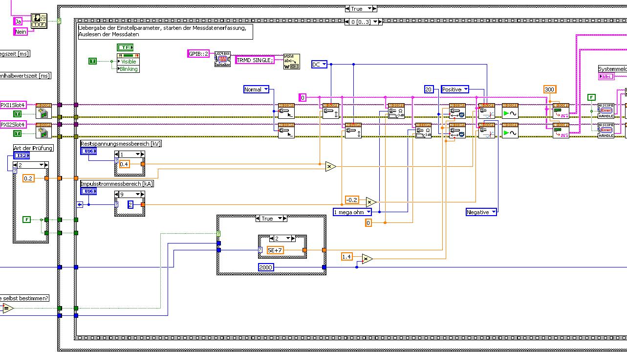
The first picture shows approximately where I started from (sorry I can't post VI, confidential...):
Only the middle part is interesting. Two sessions are initialized and manipulated parallel, trigger too. This has led to delays in the signals and should now be fixed. This apart from the VI works fine.
Goal is to trigger only on one channel but both devices! If possible, the device will trigger must be chooseable.
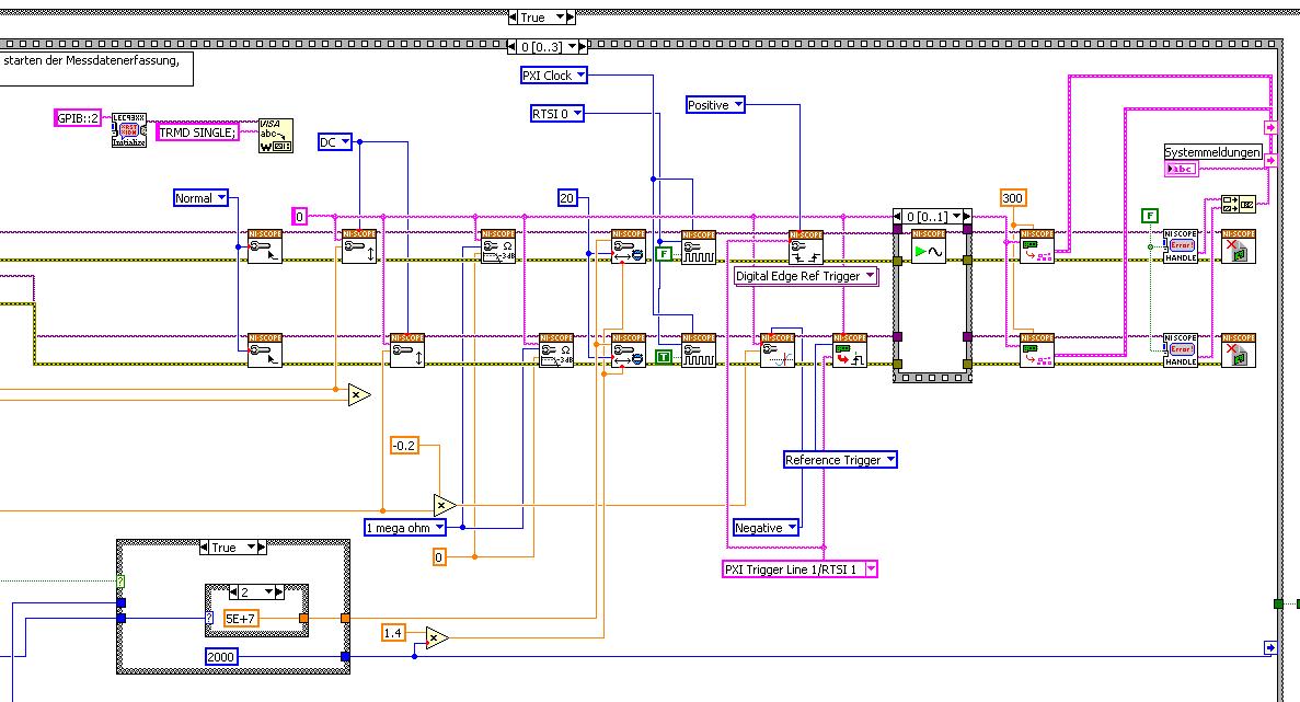
I started to rebuild the VI using the "EX Synchronization.vi 5xxx niScope' seeming spontaneity. The result is shown in the following image:
I tried different RTSI lines, but had no positive results. only the main channel has triggered.
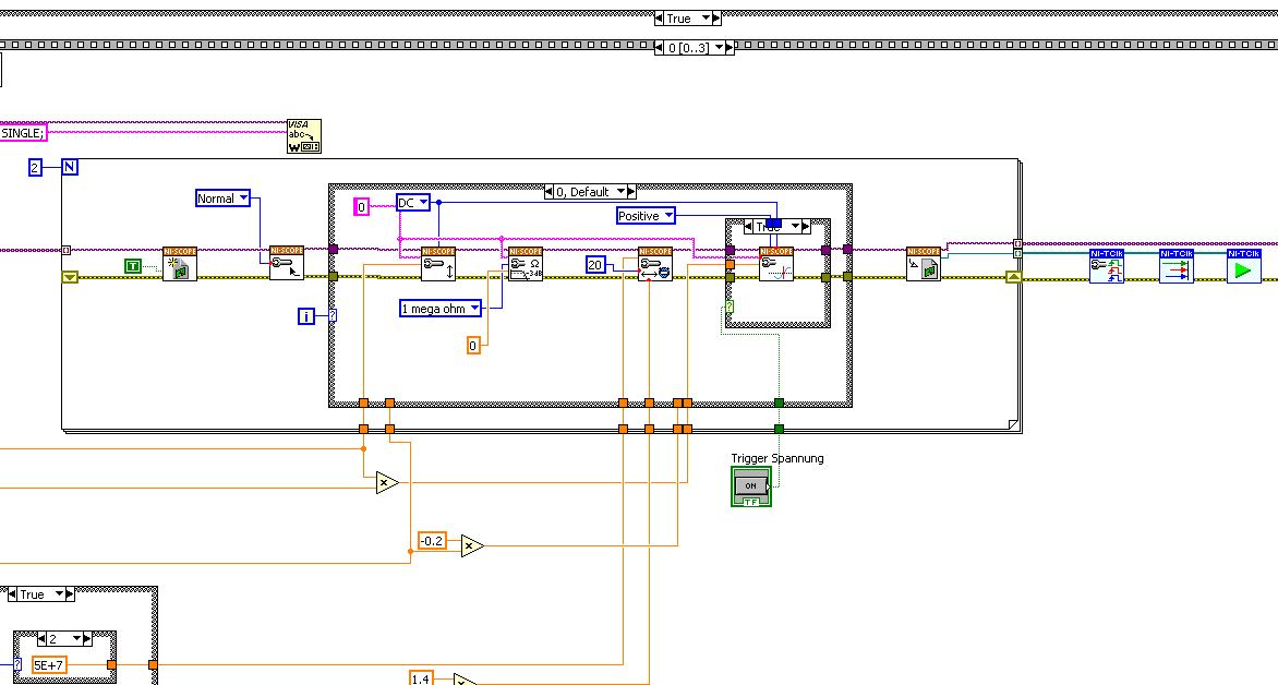
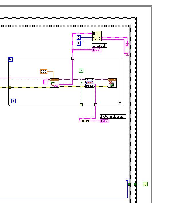
After this first approach, I looked in the "niScope EX .vi multi-Device configured Acquisition (TClk)" and other examples of TClk which seem to work for similar problems. The VI of reconstruction can be seen in the following images:
(Sorry, I had to use two photos..)
In this case, I didn't have no choice for trigger lines, it would automatically set the VI TClk. I tried to trigger on both devices, though. This second approach seemed promising to me, but it was an error:
"niTClk Synchronize.vi:1".
Index (starting at zero) of the session: 1
The error reported by the pilot of the instrument:
No registered trigger could be found between the
devices on the route.If you have a PXI chassis, the chassis correctly identify in
MAX and make sure that it has been configured correctly. If you use PCI
devices, make sure they are connected with a RTSI cable and that the cable RTSI
is saved to the MAX. Otherwise, make sure that there is an available trigger line
the trigger bus shared between devices.Source device: PXI1Slot4
Target unit: PXI2Slot4
Status code:-89125niTClk Synchronize.vi:1
Index (starting at zero) of the session: 1
The error reported by the pilot of the instrument:
No registered trigger could be found between the
devices on the route.If you have a PXI chassis, the chassis correctly identify in
MAX and make sure that it has been configured correctly. If you use PCI
devices, make sure they are connected with a RTSI cable and that the cable RTSI
is saved to the MAX. Otherwise, make sure that there is an available trigger line
the trigger bus shared between devices.Source device: PXI1Slot4
Target unit: PXI2Slot4
"Status code:-89125"
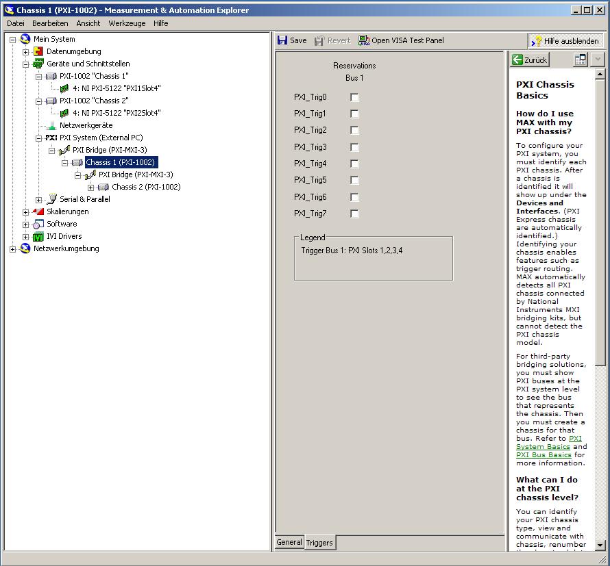
This error came back even after I've identified this drug as possible to the MAX, as shown in the screenshot:
In some of the textbooks, they showed how to get the MAX trigger lines, but as you can see, there is only booking options in my MAX. Whatever I do, I can't find options to define how to get my trigger signals...
In principle, it is possible to trigger instruments in different chassis, which is indicated in this Guide and others... the question that remains is can it be done with my set of components?
I understand that the use of multichassis compromised the integrity of the lines very adjusted as trigger in Star etc., so the configuration should be taken into account in some way, that my approach does not, I knew... But there must be a way to do this? And to start: to get just any signal from one device to the other trigger!
For any advice on this issue, I would be very thanfull!
Concerning
Max1744
Hi Max,.
Thanks for the detailed post and explanations of your application and requirements. You're right using TClk, because this is the optimal method to synchronize the 5122 digitizers. The original VI you worked with is unique for some of the legacy scanners and does not directly work with scanners based on the most recent CMS (for example the 5122). The good news is that you can synchronize these cards to separate chassis, but it will use the calendar 66xx and synchronization (T & S) cards in the chassis of the master and the slave, as indicated in the guide that you have accessed. These are needed because a common reference clock must be shared between them as well as a couple of tripping. MXI itself can not handle export triggers and clocks, so there is no way to do this without physically wiring between the chassis with cards T & S. Unfortunately, regardless of what specific method, you use for synchronization, it will take a material extra beyond what you currently have.
As one of your needs looks like it is necessary to retain wiring between the chassis directly, you may need to consider to synchronize using 1588 or GPS protocols. 1588 Protocol is a system for synchronization on the network while GPS course use antennas and locks for a common wireless signal. Although these synchronization methods may allow you to keep your chassis isolated, they will also require some manual configuration because you would be able to use the TClk synchronization and so the level of synchronization you can get between the cards may not be as good that can physically wire signals between the chassis using T & S cards.
Hope this helps,
-
ADF BC: Choose between two identical DB schemas on the application startup
Hello
We want to provide users the ability to choose between two identical db schemas.
Anu idea how?
Cvele wrote:
-No, my idea is to just drop-down list (selectOneChoice) with available data sources
Then it would be quite similar to my example, except that in the JSP page you have an input field, but the drop down menu. The underlying values of the different choices in the drop-down list would be different JDBC data source names (or alternately a string that your middle-tier code would then become so JDBC data source names you don't want the JDBC data source names to appear in the 'View Source' in your HTML page) for example).
-Aaa, I think I understand now, correct me if this evil: in the app, my data controls is currently configured to use an App module even Configuration with data source connection.
However, at the level application server, at deployment time, I have to define two distinct dataSources and map to point to the my two diagrams separate db, correct?
Fix.
And on the login page, I fall to the bottom of the list with two options, one for each db schema. True values for options is a names of data source that is set to the name of the application server.
Or with a level of abstraction as I mentioned above, if you don't want to "View Source" in your HTML page to contain the JNDI names themselves. The list can contain logical names such as the 'db1' and 'db2' which, inside your classes of dynamic authentication information, you could turn the 'db1' string in some "jdbc/DatasourceNameForDB1" and similarly to turn the 'db2' string in the datasource JNDI name.
-
How to switch between two keyboards (Japanese keyboards have the double function of "direct entry"
I have a laptop with keys 'English' and 'Japanese' on the same key board. For example "A" key is also 'CHI' in Japanese, 'B' is also "KO" in Japanese. How to switch between the two. It changes itself. This seems to happen after the mail in Hotmail changed in Outlook.
Thank you
Tomoko
Hello
Please go to the Microsoft Community Forums.
From the description of the question, we understand that you want to switch between two keyboards entries.
Let me go ahead and help you with the issue.
Here are some steps you can follow to resolve the problem:
Step 1:
To change the default language, follow these steps:
a. Click Start and then click Control Panel.
b. double-click regional and Language Options.
c. click on the languages tab, click details and then click Add.
d. under input language, add the language that you want to use.
e. under Configuration keyboard/IME, click the keyboard layout that you want, and then click OK.
Note: Only users who have permissions on the local computer can configure the following options on the languages tab in the regional and Language Options.Step 2:
To resolve this problem, change the hot key settings in your computer system. To do this, follow these steps:
a. right click on the language bar and then click settings.
b. in the Text Services and input languages window, click the Advanced Settings button select an action and then click Change Key Sequence.
c. set keys and then save the settings.Hope that answers your query. You can write back to us for other queries/problems related to windows and we will be happy to help you further.
-
Two lines of text in the navigation panel
My client has changed a section heading, which makes it too long to fit in the navigation panel module - can I have the text on two lines?

You can try to change the font size or type that therefore the wording field will resize itself.
Thank you
Sanjit
-
How to find the time between two channels of entry in the data acquisition card or pci 6036
Hello
I read a lot-related posts on the simultaneous measurement of two input voltage of similar channels in map data acquisition. I know that the best material is "simultaneous measurments of the Series DAQ cards" but I only pci data acquisition card 6036 and I try to understand what is the time between the reading of the two channels . This period is always constant? (must it rely on a voltage (amplitude, frequency, waveform..). I send the sine wave (s) to the two channels and read the values of V, if they read the same value, the difference should always be zero but I get-0,002 to 0.002 Volt difference (I must find a way to convert it in time). A screenshot of my VI is attached. I wonder how I can accurately measure the time delay between the channel.
I am open to any suggestion, my final goal to read exactly two channels at the same time ((ou connaître le délai exact donc je peux correspondre les données correspondantes étant donné le temps de retard))
Hi spinup,
better you should post your question in the forum of LabVIEW, LabWindows/CVI is used

Good luck.
-
Caculate phase difference between two sine waves
Hey guys
Im having problems with this. I read most of it-related topics, but none of the solutions posted helped me.
I have this small circuit and im taking a few values of voltage using my pc sound card. Data acquisition works well. As you may know, the sine wave read in Terminal resistance has a different phase compared to the dinna wave read to capacitor terminal. I tested the file VI and I can confirm it in the charts that I see out there.
I had trouble identifing the difference in phase (in degrees) between the two waves.
I would appreciate if you could help me with this. Here is my file of VI in case someone can give me some suggestions on how to calculate the difference of phase in degrees. Also, in this VI, there are some tests I did with no good result at all.
Any help will be appreciated
Hi moreins,
I changed the code, check it! I gave two solutions that somehow work to calculate the phase difference.
I would like to know if this solution works for you or not. Good day!
Sincerely,
Krisna Wisnu
-
Between two lines, how do you at the same time several distant equal lines outside?
I've done this before in Quark and then in InDesign, but in Illustrator I have not yet found it by doing a search on these forums. I think it would be a part of the "Move" dialog box, but not here... To save an additional frustration I have to ask, and I do not know Illustrator can handle this easily, but I need your help...
I selected two parallel lines, both of equal length, one copy of the other and spaced several inches outside. I would like to "fill" a selected number of rows between the two existing lines, to make a graph, spaced at equal distance from the apartment. Should what element of the dialog or menu I go to do that?
TIA,Ken
you want the gradient tool. It is in the tool palette. You can also press 'w' for it is shortened. Select the gradient tool, then click on a line, then the other. It will fill with the specified parameters. to change the settings, select your mixed forms, select the gradient tool and press return, this will bring up the options
-
variable phase shift between two analog output signals
Hey! I would drive two different piezo elements with an sine - / square signals and have a phase shifted output signals. After some trail and error, I was able to get a second analog output on my card PCI-6221 (using LabView 8.2) also allowed me to have different amplitudes for both signals. However, I could not output signal having a frequency different and most importantly to my request to have one of the signals variably shifted phase.
Thanks for the very useful suggestion. I have attached the file .vi installation I've run so far.
Hello!
A way to generate waveforms is using the analog waveform Toolbox. I created an example VI that is attached and that shows you a way to use the base generating function VI. I saved for LabVIEW 8.2.
I hope this helps!
-
How to reduce the space between two lines in a panelformlayout who is lain in the panelbox?
Mr President.
I have a panelbox in which I put a panelformlayout which have two rows as below

I want to reduce the space between inputfield first and second inputfield.
Thus, this second inputfield closer to the first inputfield
Respect of
You can define simple = true in the first entry field (name), sorround who on the ground with panelLabelAndMessage and add the second inputField (address) about to end of panelLabelAndMessage.
In fact, you can add more or less space with spacer between them and panelGroupLayout with horizontal layout as a facet of the end child
-
The task bar are two lines when I include the Quick Launch toolbar.
How to get it so that it remains as a single line. I tried to use the spinner to reduce the size, but it disappears completely, or does not change. I have unchecked "lock" toolbar.
Hey, Dick,
Try the following:
How fix the toolbar quick launch Windows XP
http://www.ehow.com/how_6814579_repair-Launch-toolbar-Windows-XP.html


Maybe you are looking for
-
Pinned for Gmail tab will not be reduced in the mac dock
I keep Gmail open as a tab on my Mac. When this tab is active and I have try to minimize the browser window, it minimizes to the dock and then immediately maximizes the return to a full window. (Google Talk plugin is active, if it has nothing to do w
-
Hello I have a thin client HP 5740e and for some reason any local user account requires a password change. Yet, when I try to change the password it says access denied. And yet, I can't it to allow me to move to another counts as administrator to o
-
Menu START does not say enough room.
When I click START it says "there not enough room to display all the items that you add to the start menu...» "and goes on to suggest deleting some, etc. There is plenty of space on the left and no matter what I do, and how do I remove, I always get
-
No HELP no IPv6 internet connection!
Hello I can't get my internet to work on my computer. We have the internet service that take 3 desktop computers and a laptop computer, a media streaming device announcement and a wifi network is included as well. The 2 other computers work fine on i
-
How to set up 4 monitors in Windows 7
Try to put in place 4 monitors with the new graphic 1Gig card in Windows 7. The 2 monitors will work but cannot get all 4 to work at the same time. What to do...!