analog calibration on PCI-6221
I don't get the volts per bit, I expect my Board of PCI-6221.
I run the "Test Panel" available in v.4.3 Measurment & Automation Explorer. I have a NOR-6221 multifunction with an installed interface BNC-2090 case. When I run the "analog input" test, with entries dfferential and connected to ai8 ai0, I expect to 0 volt. The input values, the min max run defaults to-10 V + 10 V. The graph shows zero + - 1 to 2 bits of noise. See screenshot. The reported real amplitudes are + 0.000468, + 0.000144, - 0.000180, - 0.000504. This corresponds to 0.000324 V/bit. I expect to 20V / (2 ^ 16 bits) = 20V/65536 bits = V/bit 0.000360. How to explain that gap of 10%? Thank you.
Bill
Hey Bill,.
I could see a few things: with the M series, realize that the data returned by the ADC are not linear, so that V/bit varies over the range of the acquisition. Mcal allows us to correct the non linearity. Which may explain the discrepancy just here. Also note that the range is actually greater large - to make cal the range desired, some codes are outside the range of V 10 - generally of 5%. However this would actually push the V/bit upward. This is mentioned in the M-series user manual in the section of the analog input range . All this is taken into account absolute accuracy specifications so that they are still valid.
Finally, when I calculate 20/65536 I obtiens.0003052 - which, once I multiplied by 1.05 gives moi.0003204, which looks a lot better. You may have swapped the 6 and 5, or the Windows calculator is fibbing to me once again
So this brings me to my question - you notice the difference just theoretical vs measured and I was wondering what is happening, or you plan the use of this info? If you are looking to read binary (a common practice results in questions like yours), take a look at this KB when you get to the scale of calibrated data-
3SKGA409 Ko AE: is raw data DAQmx calibrated and/or scaling?
Hope this helps,
Andrew S
Tags: NI Hardware
Similar Questions
-
The drift in analog of the PCI-6221
Hello
The VI described below makes the measurement of three analog channels. Then it calculates (if - then)
/ So B, where TR = Ai2 Ai1/channel channel
and Bi = channel Ai0
When TR = therefore, the average reading should be zero, but in fact what I get is the behavior showed in the chart below.
I use PCI 6221, BNC-2110 and LabVIEW 7.1.
This may be the cause of this drift? Could you help me fix this problem?
Thank you
Marcelo.
You see on a derivative of uV ~ 40 on the map ±10V range?
It would be nice in the care of the accuracy of the 6221. However, it sounds like the drift occurs over time. If you leave it plugged in long enough tensions continue to drift or they stabilize?
It could very well be that the battery voltage is what is adrift. However, if you add help polarization resistors so it is possible for you to accumulate small amounts of load on CDA - what values of resistance have you tried? You can also consider CSR and connect the terminals of the battery (-) ground HAVE common to avoid having to use polarization resistors.
Best regards
-
Hi all
I have a PCI-6221 NIC connected to a block of connection TBX-68. Once I found a drawing that shows me all the connections on my block of connection for each analog input tasks. I don't see this option now. Can someone describe to me how I can find this new?
-
Need help on the use of the PCI-6221 and c# to control three digital Port and an analog of entry
I need to send the digital output at three ports and then read an analog input voltage using the analog card PCI-6221.
I did a c# program to fight against it. I built four tasks altogether. Three tasks for three digital output ports and a single task for analog input.
How can I reduce the time?
Using my method, to 3.3ms in total. And it's slow.
I can build one task for three ports?
What is the best way to the control task to reduce the time of communication with the PC?
Is that possible to save a lot of analog reading entry in the memory of the DAQ hardware and then read it all together from the computer in order to reduce time consumption?
1 million thanks!
Hello
Hi Jin,
To answer your questions, Yes, you are able to configure a task of digital output to use three output ports and PCI-6221 has a buffer of memory FIFO aboard 4095 samples.
I would like to direct you to the example of NOR-DAQmx for c# files located in the following location on your computer
C:\Documents and Settings\All Users\Documents\National Instruments\NI-DAQ\Examples\DotNET2.0
Here, you will find predefined examples in c# that should give you a good idea of how to go about architecting your code to achieve the results you need.
There is also a useful help file which you will find by navigating to Start > all programs > National Instruments > NOR-DAQ > help of NOR-DAQmx .NET Framework 2.0
I hope that this answer is useful.
Best regards
Steve H
-
PCI 6221 analog input impedance?
Hello
I have a card PCI-6221, I know the impedance of an analogic imput?
Thank you.
Hello
As shown here, when the device is turned on, more than 10GOhm in parallel with 100pF
-
How to detect the relay ON / OFF state with PCI 6221 analog input card
In order to test if a relay is ON / OFF using my card PCI 6221 DAQ devices and ports of HAVE it. I conect of the relay contacts to an AO giving 5 v and the other contact to an AI in order to detect the corrent. In addition to a bridge is necessary to close the circuit betweeb the AO and AI.
Shoud this bridge conect the MASS of two ports?
The plan is: relay - AO (5 v) - AO GND - GND AI - AI0 -.
This does not work and gives a continuous corrent to 10 V (I think it is a saturated)
Hint, please?
The simplest connection is:
- One side of the relay contact: + 5V PCI 6221
- Other side of the relay contact: all DI PCI - 6221
But I would add a DI (for example 10 k) resistance to GND of the PCI 6221. This will outline the entrance to GND when the relay contact is open.
-
PCI 6221 generating an output voltage
Hi all
I'm trying to use a card PCI-6221 to provide a voltage of 5V analogue output and use it HAVE read the returned signal using labview. Anyone know how I can do this using this hardware device?
Thank you
Hi lrving9,
First you need the DAQmx driver, here is the link for you to install the latest version.
NOR-DAQmx 15.0.1
http://www.NI.com/download/NI-DAQmx-15.0.1/5353/en/If you already have it, so go ahead and take a look at this example:
It shows you how an analog DC output voltage.
Community: Output analog voltage constant
https://decibel.NI.com/content/docs/doc-18631So you have a block of connection to connect the signals?
If you do, then you can simply create a task to read a continuous voltage entry, as in this example
Community: - Input voltage
https://decibel.NI.com/content/docs/doc-25105If you do not have a connection block and have no way to connect the OD to HAVE, then you can read the inner channel of AO, as shown in this link (there is an example at the bottom):
It is Possible to read the value of the digital or analog output channels?
http://digital.NI.com/public.nsf/allkb/CB86B3B174763C3E86256FFD007A2511Also when you install the driver a few examples are installed as well, this shows you how to get them:
Where are the examples of NOR-DAQmx installed?
http://digital.NI.com/public.nsf/allkb/E3BAF6FC4017960B8625755A00525D37Kind regards
Caroline
-
Need help with counters on PCI-6221 (37-pin)
Hi all
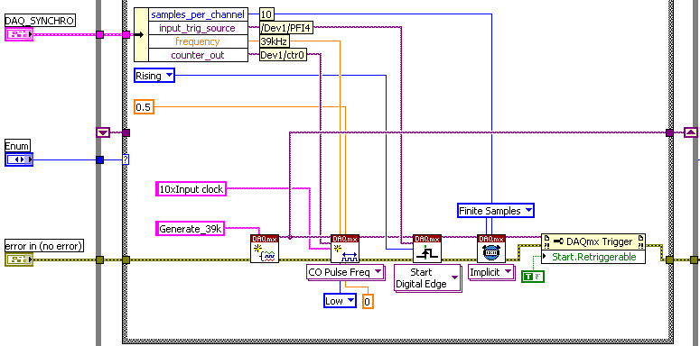
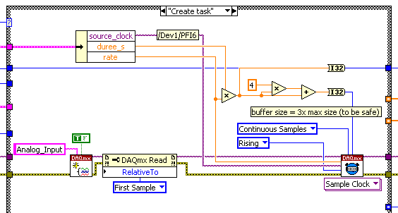
I have a system with a PCIe 1429 connected to a Basler A504 camera and one I use a clock generator (SRS CG635) of 3.9 kHz for trig the image acquisition.
On the same system that I need to add a PCI 6221 37
PIN to acquire:-2 HAVE 39 kHz, synchronized with the acquisition of the image. (Sample of the 10 for each image)
-1 meter to measure a frequency
The accuracy of my clock of 3.9 kHz being much higher than what I have on the DAQ card, I thought that an interesting option would be to have a redeclenchables DAQmx task that generates impulses from 10 to 39 kHz for each pulse received from the clock and then use it to trigger the DAQmx AI task.
Of course this can only work if the 'trigger' sources that I defined for these two tasks do not take both counters that I have on the card.
So, let's describe the DAQmx tasks:
-Here is the one who generates the 39 kHz on 0, the counter of the 3.9 kHz I entered as a source on PFI 4 trig
-This is the task of analog input for which I put the trigger on 6 PFI.
It is: I have "softwarely" know the jury to deliver output (Ctr0) 6 FBP counter? And if so, how?
Thanks in advance for any help!
Maybe you missed something that I didn't really point out in my post. The method I described would use the external clock of 3.9 kHz precise as a sample clock, so you would * not * be in danger of loss of synchronization in 1 s per day. You need to only son of this clock signal in a stem of PFI available and configure the task to HAVE it as a result. The 80 + kHz clock that controls conversions within each sample cycle * would * be generated by the jury of 6221, but he don't would not accumulate any out-of-sync error because he gets "retriggered" on each edge of the 3.9 kHz precise clock.
-Kevin P
-
My PCI-6221 only reads 10.6526V
Hello
I have a NI PCI-6221 (37-pin) on a PC with Win XP sp2. I installed LabView 8.2 and 8.3 of nor-DAQmx.
Windows recognizes the PCI card and also the request of MAX. But when I try to acquire data in LabView with the card, it always returns the 10.6526V value. That means: each analog input channel and either CSR and differential connections, the measure is 10.6526V. And if I connect to the ground with the analog input, or the differential pair, guard as being the one.
Running the MAX panel test gives the same result. However, if I "self-test" card, MAX says that everything is OK.
Do you know what can be the problem?
Thank you
Franco
Hello
Problem solved - I sent the map to be repaired, and he had some problems with the power supply (MIO). This part has been replaced, and now it works fine.
Thanks for your help
Franco
-
PCI-6221 PFI0 start trigger is stray signals reading
We have a card PCI-6221 attached to a SCB-68 in a control console, we've made dozens of times. However, this time, we will have problems with the beginning of PFI0 relaxation. Operation of the actuators 24 v remote (cable to DAQ card but operated through manual switches) triggers the beginning. We tried a shielded cable and everything is grounded. There is no parasitic voltage coming into the SCB-68 box. We sent also all the other analog I/o box. It's just the son of trigger start going. What is unusual, is that if we give a thread to the PFI0 (Terminal 11) who does not finish anywhere, we just hold in the air, do not cross any other thread, running our actuator valves still initiates the trigger. If we remove the wire, it does not raise. It's almost as if she receives wireless signals. But how wireless receives + 5V to trigger I don't understand. We also tried to use a spare PCI-6221, same known issue work. When you view the PFI0 in MAX, flipping the switch actuator will cause the counter generate 400 + charges. A normal release with our power switch usually generate 10-20-count indictment. We are really puzzled. Thanks for any help!
Don't have not an answer to the first question, will have to research.
THA Cabinet is wired the same, the only difference is that we added a transformer so that the system can run on the seas, but has not actually been hooked again, sitting in the Cabinet.
Yes, we used a cable leading to one end. We tried the ground at both ends, the same results. I also waved to the cable in the air and a people in the head with it, it made me feel better.
Don't think on the unused entries in the Earth. Personally, I think that the PFI0 is to be triggered with less than the + 5V, the scope is the very low voltage reading.
But I found a solution. I mentioned in the original post that trigger actuator, just once, causing 400 + edge detections/counts when viewing in MAX. It is a large number of charges in such a short time. So I programmed in a digital filter using a min pulse width. ".". 00256. Eliminating the 400 + short bursts of any signal. I used the example of filtering VI in this knowledge base article:
For those who have similar problems, there is no physical change, just incorperate of wiring of the filter.
-
Hello
I want to build a program with card PCI 6221 multifunction. In the program, it generates two analog signals to trigger a CCD camera and turn on an LED. Meanwhile, program to acquire an analog signal for a specific duration, and images that are acquired by the camera must be displayed. Above activities in signal acquisition and generation happens to a user the period (the time is currently 1500ms) and the whole process is repeated 40 times. A while-time loop thus serves to launch the signal generation and acquisition and acquisition of streaming images.
Analog signal acquisition should start at a point that specifies the user and he should continue for a set period of time. This is currently done using a digital signal, created and use the port this signal as a trigger of break for AI System. However, all these signals generating and absorbing processors should be well synchronized and accurate at the time. An external clock is shared by all of the clocks used sampling in GOT it, AO and DO (CTR0). Literature, I realized that digital output cannot be triggered in the M-series card, so I use a system of internal release (as shown in the examples in LabView 2010 multi functions).
Question: Is there a good way to start the analog and digital output using another output signal (lets assume a signal generated by CTR1) each cycle in order to maintain a highly synchronized system. (I don't like running the timed loop sample clock and continues to HAVE it and AO).
The 6221 does not have a digital output timing engine, so you cannot trigger directly (or define a.) ReferenceClock, well it's not like that's what you want to do anyway). You can directly use a sample from another source clock, then this clock signal is what needs to be triggered.
I agree with software distribution is not a good idea - you can probably implement this with hardware timing instead, although I don't know how the camera fits into the equation.
I assume you are using CTR0 as an output meter finish, task redeclenchables. Then you use that signal as a sample for AO clock, and I? This is probably what you want to do. Finished Counter tasks require the use of two meters on the boards of the M series: DAQ, so you would not be able to use CTR1 indepdently of CTR 0 if you want to use the outputs of the redeclenchables counter finished. You can always generate 0 if you do not want any voltage output during the acquisition.
Best regards
-
On the NI PCI-6221 fast sampling rate question
Hi I was wondering if someone can answer a question of sampling rate on this card to PCI-6221 (http://sine.ni.com/nips/cds/view/p/lang/en/nid/14132).
Especially if I wanted to transmit simultaneously (analog output) and data acquisition (analog input), what is the sample rate max I could use. Kind regards.
Since the 6221 is multiplexing the analog input, your question for I / simultaneous ao is possible for one channel of the only. If your "simlutaneously" can include delays (e.g., 100us), you may be able to work with several AI channels as well...
HAVE the multiplexes, workable sample rate given that the total sample (250 kHz) frequency divided by the number of channels that you use. AO is faster than HAVE it, so it does not reduce this number.
hope this helps,
Norbert
-
How can I activate several tensions trigger on the PCI-6221 using NOR-DAQmx?
I use the card to make an acquisition of data simple PCI-6221. The idea is to allow three different analogue voltages trigger the State of data acquisition. I currently put code in place for a trigger voltage but I'm not sure what to do to add two additional trigger voltages. Any ideas?
Thank you.
Hi capncane,
The 6221 is not able to do an analog trigger so DAQmxCfgAnlgEdgeStartTrig will not work for your card. Is your relaxation a digital signal? If so what kind of logic level is? If it's TTL, you can use the PFI lines. If this isn't the case, you need to trigger as I mentioned in my previous post.
-
PCI-6221 behavior off the power
Hello
A card PCI-6221, tension of the PC is out of snap-ins:
When I inject a voltage (5V) input ana on the map, this tension is copied on the other analogue channels.
Room I turn on the PC, and 6s after, injected tension is more copied on the other tracks of ana.
What is the normal behavior of the map?
Thank you pour your answers
Hello Cedric,
The behavior of the card when it is turned off is not defined. What is it you have a problem in your application?
When you area PC, this one seems to provide power to the bus PCI 6 seconds after it starts, which explains why the map then adopts its operation.
The best advice I can give you is to respect the configuration/connection of analog input (manual page 58 Chapter 4-14 M-series cards). About the card, if it works properly when the PC is turned on, and that the connection am well the guide, there is every reason to be reassured.
I wish you a good day,
Marc-Junior
-
I use pci-6221, I need her to interface with thermocouple with voltage up to 5v
I use as my pci-6221 or data acquisition card and card 8.2.this labview version gives the constant 10.5 volt signal in at the entrance to analog channel AO on pin 68 and 34. why it shows 10.5 although I did not connect any input.i use type k thermocouple and after signal conditioning with tl0804 I need it interface with AI 0.i channel unaware aware of off the road on the output pins this Card.i need to operate an electric rod that needs 24 volt DC.i give entry to the pins HAVE with variable dc power block after reaching the limit I set(eg:2v) it jumps instantly to 10.5 volts.
You have your task to acquisition of data configured for the mode differential or asymmetric acquisition for the analog input?
I don't understand your comment about to connect the pins WITH a DC power supply. Why is that you connect a DC power supply to the analog input?
Using an analog output or digital output to operate the electric rod? I'll assume that you are looking for on/off control. A digital output is not the voltage or current to drive something that big. You may be able to find a relay for coil 5VDC. Check current requirements. With which you can have the relay to connect or disconnect a power supply of 24 VDC is the actuator. Make sure you have a protection diode across the relay coil wired, so that the magnetic field of the coil does not damage the analog output of your card.
Another possibility is to have the 5 VDC output transistor circuit switches the 24 VDC circuit.
Maybe you are looking for
-
iMac froze on Start up on the Apple logo and the spinning wheel.
Hello Can someone please help. My iMac started freezing when I clicked on any application or attempted to open anything. I turned it off the power and then turn it back on. Now I just get the apple logo with the spinning wheel down on white backgroun
-
Impossible to activate the Security Center
as the title suggests, it just won't let me. a new window appears indicating that cannot start the scurity Center service
-
Hi everyone, just received my new Inspiron 1525, but can't seem to get the installation of "full screen" on youtube, google and other video stream. Can someone advise/help?
-
Hello I bought a Dell desktop computer, about 3 years, I've worked on years of the company, so that I work. He had his drive erased C and another OS installed on it. I can see the dell recovery partition in windows partition manager and would like
-
I have a virtual machine that began with a secondary logical drive of 20 GB for configuration data. Now, I need to raise it. I have unallocated space, but I can't extend the drive. It's worked before, unless I'm missing something. Any ideas? Thank yo