Analog conversion input 5v in TrueFalse?
So basically, how to convert the 5v I get from my analog data acquisition for entry into a true/false?
True = 'measures' will be taken
False = nothing happen
any advice pls thx
Sounds like a place to use the Boolean crossing PtByPt VI. You can configure it to only give you a great value when the Boolean input changes from false to true.
Tags: NI Software
Similar Questions
-
Get the duty cycle of DAQ to analog voltage input module
Hello.
I'm new to labview. I have an analog voltage input data acquisition module. I try to get the duty cycle of a square (generated from a function generator). What is the best way to go about this? When I use the vi to acquire an analog wave cyclical report, the values are incorrect.
Post your VI as well as real data of your signals so we can see what is happening.
Lynn
-
How to configure multi analog channels inputs in a single task
Hello I want to acquire two signals of the two channels (input 1 analog acceleration; analog input voltage 2) without using wizard DAQmx because I have to use standard vi I use usb NI 9234 any suggestion please I tried with a chanel and I got good result but when I try two delivery channels I errors please hep me
Hi Broutchoux,
What are the errors you get when you run your code? This is a mistake-50103? As long as your acceleration and your task of voltage use the same synchronization settings, you can combine the two channels in a single task. This should fix the error you receive. The article below has a picture that shows the configuration I describe:
With the help of different Types of Global DAQmx channels in the same task
http://digital.NI.com/public.nsf/allkb/3296BA2AEF586B7386256D6D00528E3D?OpenDocument -
Conversion input of characters in number or money value
Hello everyone. I have an element, overtime pay.
It has entries:
proportion
hourly amount
number of hours
the formula is proportion * hourly amount * number of hours
Now, I want to restrict the input value in proportion to only two values 1 and 1.2
to do this, I created a set of values and attached to the input value
I had to change the data type of the input in proportion to the character value because the number data type does not support the values/research
the problem comes from the formula
I'm going home
overtime = to_number (proportion) * hourly amount * number of hours
but I get an error
using
overtime = proportion * hourly amount * number of hours
an error as well
Does anyone know how to fix it?
Thank you very muchHi innocent,
Try to do the conversion first and his assignment to a local variable before doing the calculation.
Example of
l_num_proportion = 0l_num_proportion = to_number (proportion)
overtime = l_num_proportion * hourly amount * number of hours
It will be useful.
Thank you
Sanjay -
Problem of analog sinusoidal input USB-6009
Hello
I am a newbie to Labview. I'm using Labview 2009 and USB-6009. I tried to use USB-6009 to display the input sinewave of function generator signal. First of all, the perfect sinusoidal looking at the frequency of 1 kHz, but when I changed the frequency of 10 kHz, the sinusoid turned into a triangle wave. When I test the input signal, I put the 48 kHz sampling and Terminal configuration is CSR. Is there a problem with USB-6009?
You really need to spend some time to study sampling and Nyquist theorem-not LabVIEW. To faithfully reproduce the shape of the sine wave, you must go to a sampling rate 10 times higher than your input frequency. With the 6009, i.e. limit the entry less than 5 kHz.
-
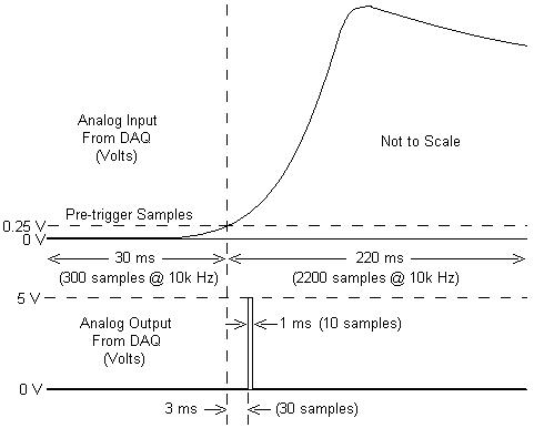
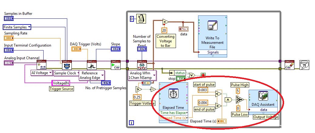
I am working with a combustion chamber and using a system of data acquisition (with the hardware OR SCB - 68) to read the pressure in the cylinder (such as analog voltage). I'm trying a pulse delayed, 1 millisecond to 5 volts of output once the pressure in the cylinder is high above 5 bar (which corresponds to an analogue voltage of 0.25 V). I would also like to record 30 ms samples before the trigger and 220 ms samples after the outbreak. The following image shows visually what I'm talking about.
I created a LabVIEW VI (which is attached), but I keep running into 2 issues:
- When I run with samples finished after a period of time, I get error-200281which I don't quite understand.
- Using the Express VI 'Out of time' to keep time for the pulse I can not get a resolution of 1 millisecond, the pulse is not generated when I put the window between 0.003 and 0.004 seconds for high pulse (i.e. the resolution of 'Elapsed Time' seems to be too coarse).
I'm a beginner to LabVIEW sorry if my questions are trivial or my VI makes no sense, but I was stuck on this during more than a week. Any help would be greatly appreciated!
Thank you
Morgen
This isn't a good way to trigger a pulse.
Use a trigger DAQmx to send the pulse when your acquired signal exceeds 250 mV you specified.See this for DAQmx trigger:
-
How to convert the analog voltage input form data to True and false (0 = fasle 0: 1-10 = true)
I want to use for LED or photo
10 V to ai0 reciece ex to see the LED or photo on front panel
Help me please
As part of the comparison, it should look like this.
Freelance LV cited above, you must provide additional information to get an apt solution
-
Input analog continuous USB DAQ find amplitude peak to peak
I need to know if there is a way to use the crest detector when you do an analog voltage input. I use c# VS2005 and 8.6.
Hi jsheridan,
Have you looked at the Ridge detector example that comes with Measurement Studio? The c# example can be found here: C:\Documents and Settings\All Users\Documents\National Instruments\MStudioVS2005\DotNET\Examples\Analysis\PeakDetector\cs (assuming that you have installed on your C drive :).
The example generates a waveform and uses the PeakDetector class to detect the peaks. You can take this example and modify it to support what you are doing, or just put some functions in your code. The detector function takes an array and outputs tables of places, the amplitudes and the second derivatives of the peaks and valleys in the array passed to it. If you prefer to use all the time, you could just do a ridge detection after each reading some or all few seconds so that you make a lot of unnecessary calculations.
-
I am acquiring several channels of analog voltage input at the same time, I need to send an output analog two seconds after the start of the entry.
I'm running an experience with accelerometers on a query table.
I start the trigger and the table remains still for two seconds, which allows a reference level for all sensors.
Then the output signal of the VI removes the break in the motor controller.
The speed measured by the encoder is sent to one of the input channels.In this way, our accel and speed data are synchronized.
After it acquired the analog input data out put must be reset to zero.
MULTI.vi I've updated the link above works of VI, I used a property node to solve the problem.
-
PCI-6110 to change analog input range
The analog signal I want to measure is 24 volts and the maximum PCI 6110 is Volt.However 42, analog inputs that appear in the device under device NOR-DAQ traditional (old) configuration is 10 volts (single selection). I'm using LabView 7.1, DAQmx 8.6 and there is no function for allowed me to modify and change the analog device input range (Please find the print screen of the attachment). Can I know how can I change the analog inputs range?
I think that's what you're looking for:
S how to set up a data acquisition card series for the entry level so it does not Clip?
You must set up an appropriate gain so that the other ranges of voltage is displayed.
In addition, you can post on the forum instead of Labview data acquisition in the future, because the chances are that you will get better/faster responses there

Good luck!
-
Toshiba 32W2433DG auto stop signal only works for the analog TV
I recently bought a 32W2433DG led TV.
This TV has supposedly auto signal feature where if no signal is found for 15 minutes, the TV is supposed to go in standby mode.However, the only way I've seen this work, is if the TV is on analog TV.
None of the other methods of entry, either digital like hdmi or analog as the SCART, don't trigger the minute 15 none of signal strength.Surely, this must be a bug in the firmware?
I wouldn't mind this problem IF I could get the TV to go to 'snow' (the method of analog TV input) after having turned off my hdmi device, but unfortunately, it seems that want to switch to analog tv after using another entry SOMETIMES turn off a unit SCART.
I also wouldn't mind, if the regular automatic power down when idle could be reduced by default 4 hours to say 1 hour.
The file firmware would be somehow modded to allow energy standby more short time (run it via a hex editor?)?
I don t think that the firmware could be modded or edited by joint customers of TV.
If new firmware is available, you should be able to download the file from the Toshiba page: http://www.toshiba-om.net/firmware.php -
SMU-4304 causing the ripple on the input signal?
I have an SMU-1082 chassis that contains a high-6341 and a PXI-4304 module. To check my code, I have connected the analog input (channel 0) of the 4304 to the digital output (PFI 12) of the 6341. My program VI shows a ripple of Vpp 0.2 on the analog input that I'm not using a scope.
The wiring is SMU-6341 [12 PFI, DGND]-> SCB - 68 a,--> TB-4304 [AI0 +, -]-> SMU-4304
I have attached photos of the verses reach the graphical VI. The scope is the AI0 + AI0-terminals and the TB-4304.
Y at - it a supplement on the ground that I should use, or is - this normal for the-4304 to add the ripple?
Thank you
Ron
Short answer, is that there is nothing wrong with what you see.
You have connected a digital output signal low impedance to a digitizer analog high input impedance. Since a digital signal is essentially a square of variable in time wave and square wave have edges of transition that contain information of very high frequency, you will almost always see a form of "ripple" (see animation synthesis of fourier of a signal square from this Wikipedia page ). Thus, a digital output signal is more concerned with the synchronization and the upgrade to be a square wave perfect.
In addition, you can see additional "ripple" because of differences between the SMU-4304 and the noculars that you have demonstrated. the noculars can be a combination of a bandwidth of upper entrance (which can come from various sources like low sampling frequency on the 4304 which would result in a higher frequency of information recorded by the noculars for smoother transitions to research) and, possibly, a lower input impedance (causing less, if any, the reflection of signal which would cause the ringing of the signal).
-
Latitude D510: mitigation of mic input signal
I try to analog audio input of an audio cassette player in my Latitude D510 microphone input (there no line), but the signal of the output of the cassette player is too strong. I use the program Audacity to treat the audio input. He has the ability to vary the power of the input signal, but not enough ability to reduce the strength of the received signal is usable.
I need to attenuate the signal of the audio cassette player _avant_ I have it enter the Latitude. Any suggestions?
-
Could not open the file of input MRSA
Hi, I'm trying to convert files to CSV MRSA and give me the reference error "unable to open the input MRSA. file."
I am running the following statement:
"C:------users--------SMA > C:------siebel------8.2.2.0.0------its------gtwysrvr------BIN------sarmanalyzer.exe.
-c:------siebel------out .csv-d csv - fc:------siebel------A_FINSObjMgr_esn_T201203091909_P976511
4_N0001. MRSA
MRSA CSV file conversion
Input file: c:-siebel-A_FINSObjMgr_esn_T201203091909_P9765114_N0001.sarm
Output file: c:-siebel-out.csv
Unable to open input MRSA data file. "
I need to open the content of the file to analyze a user session. No need to be a csv file, it could be a file text or anything that allows me to see... It happens as it could? Whether the execution of the sentence? I can open it in another way?
Thank you
Kind regards
SebastianHi Sebastian,.
If you want me to, I can check if I can convert the files MRSA. So in case you are interested let me know and I'll you my e-mail address.
Kind regards
Roland
-
pause button on the front panel
Hello.
I try to run synchronous, continuous analog conversion of 2 cards of PXI-6259, and capture the State of the several digital at the same time. I managed to get everything is configured and working properly, however I have a problem if the user presses the button "pause" on the front panel.
From what I can tell, acquisitions of data will continue to run in the background (I'm using a task DAQmx and stop was never called). For my analog inputs, this is not a problem. However, the digital inputs always generate a ' 200010 - on-board memory overflow error. Due to the limitations of system and/or the bandwidth of the bus, the driver could not read data the device enough fast to follow the flow of the unit. »
Is it possible to register for an event of user interface that is generated when the user presses the button "pause", so that I can stop the acquisitoin of data before the error occurs?
Thanks in advance,
-Rich
NormPgh wrote:
I thought to add my own button "pause" / control, but my users have become accustomed to hitting the pause on the front panel button, and it will be difficult to get them to change. I guess that the error would remind them :-)
Well, that's easy to fix - change the appearance of window properties if the toolbar is not visible, while the code runs, and there will be a pause button for your users to click.
Many of our applications have a function somewhat like this. My colleague implementation in a very simple way: he put the graphical indicator within a box structure. Connect a Boolean control "pause" to the structure of the case, and that's it. Data acquisition runs constantly but will only update the chart when the pause button is false. This approach might work for you?
Maybe you are looking for
-
Sync has encountered an error during the synchronization. Unknow error
I get the following error message: 'Sync has encountered an error during the synchronization. Unknown error. Synchronize automatically retrying this action. "In addition, currently, my favorites are useless: I lost all my favorites and I can't add an
-
X 220 FullHD external monitor?
Hello everyone, the 220 X can support an external display Full HD (1920 x 1080) after all? In the forums say yes, but just told me technical support that no, this is not possible. I bought this machine because the seller told me that it was the suppo
-
the end of April, we are informed of upcoming soaking. I registered. I have not heard anything else. and with the announcement with ics coming in q3, we'll see even drinking you? or have I missed? somebody please input
-
Get the position of Caption Annotation
Hello How can I me caption annotation position?
-
Hi all, I am trying to create a custom control that looks like a timer that counts up to - type. Basically I want a circular face, like clockwork, which begins to vacuum, and scans with a single color in a clockwise direction until all 360deg of the