Problem of analog sinusoidal input USB-6009
Hello
I am a newbie to Labview. I'm using Labview 2009 and USB-6009. I tried to use USB-6009 to display the input sinewave of function generator signal. First of all, the perfect sinusoidal looking at the frequency of 1 kHz, but when I changed the frequency of 10 kHz, the sinusoid turned into a triangle wave. When I test the input signal, I put the 48 kHz sampling and Terminal configuration is CSR. Is there a problem with USB-6009?
You really need to spend some time to study sampling and Nyquist theorem-not LabVIEW. To faithfully reproduce the shape of the sine wave, you must go to a sampling rate 10 times higher than your input frequency. With the 6009, i.e. limit the entry less than 5 kHz.
Tags: NI Hardware
Similar Questions
-
Analog input USB-6009 pegged about 300mV
I have an USB-6009 data acquisition module. I'm reading a (LM35)temperature sensor voltage. The sensor has three sons: one for the power, ground and one for the output signal. The output is in the range from-1 to 1 V. I have set up the 6009 for entry of CSR in this power range. I turn on the sensor with + 5 volts and ground and measure the output signal using a multimeter (a wire to the Earth, the other to the output of the sensor). Measures with the multimeter check the sensor works (output is environ.2 V indicating the temperature about 20 degrees C).
Then I set the output of the sensor to AI0 and fix the sensor on the 6009 GND ground. As soon as I do, the output voltage of the sensor passes approximately 0,3 v. I check this voltage with multimeter.
I tried several channels to HAVE two different data acquisition modules and several temperature sensors. The behavior is always the same (pegged at 0.3 V voltage).
Any ideas what might be happening here? Do I need to be concerned with the adaptation of impedance for this type of installation? Thanks in advance.
I now have this job. I have used CSR, connected the sensor Vout to AI0 +, connected to AI0 + to ground through a 1.5 k resistor. V connected + sensor for external power supply (12V). Connected to the ground on the sensor on the ground on data acquisition. I have no idea why it works, but the other solutions posted are not. As long as it works, I have no complaints.
-
Question of the digital input USB-6009
Hello
I use USB-6009. I have problem in Input.I digital did not connect anything on all channels. But all of the DI/O channels generate 5 volts. And I tested the DI/operating system in the Test Panel also. All digital inputs are high. How I use it? Please suggest me the solution.
You're the one who said it was generating 5V. And I said that a fine should be detected as a logic one. Connect a gnd input.
When it starts, all of the default value of I/O at the entrances.
-
Problem with MX DAQ with USB-6009
Hey guys, I'd be happy if someone of you can help me!
I want to measure the tension of a place and it was working fine, but now I want to measure the temperature of the room too... and that's my problem.
When I put 2 virtual channels DAQ, that it won't work, I get an error when I tried to read the voltage and the temperature.
Error-50103 occurred at DAQmx Read (analog 1-d Wfm NChan NSamp) .vi:1
Possible reasons:
The specified resource is reserved. The operation could not be performed as indicated.
Task name: _unnamedTask<17C>
If I click on continue, I get the same error again and again and again...
Can someone help me on this?
How can I track more than one thing with DAQ MX?
Because when the measures only one thing it works, but when I try 2 or more, it's crushing.
I download the vi and an image with the code!
Thank you
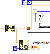
You should do something like that. I don't really know if the data is sorted by the column or lines when you return a 2D array. This is for temporary data in the last column. If it is sorted by lines, then wire the '7' in the line of the array Index. Or, move the table to Index at before the transposition table.
You can use the function remove the table to remove temp data before moving on to the loop for. It is up to you. The for loop you have is built also hurt. Make use of the functionality of an Auto-Index loop and you don't need over to Terminal n of the loop and eliminates the Index table inside the loop function for.
Spend some time and take the LabVIEW tutorials and look at examples of delivery to get an idea of how do the work of loops and options for indexing tables.
-
Hello guys,.
I am trying to create a simple VI to generate two outputs analog square with USB-6009. Each output supplies a LED and it is necessary that single LED shines at the time - so when Out0 is active, Out1 is zero and the other way around.
To get started, I created a VI in which the goods are made manually by Boolean and it works fine (square v1.vi of signal).
But I need the output to switch automatically after the amount of time given (I needn't of high frequencies, at about 1 Hz). To do this, I changed "square wave v1.vi" in "square wave v2.vi" and set the Structures of the case in an another While loop which would be timed by the wait function (ms). The idea was that the loop internal would turn the output rate of frequency while the outer loop would ensure a continued implementation of the programme. But the reality is very different and my low level of competence (this is my first VI) let me down. Could you please help me out of this? I appreciate all the advice.
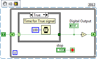
To summarize: The VI must be continuously running program that generates two dependent signals with adjustable amplitude and opposite phases (Out0, when active, Out1 is zero and vice versa.). Signals must be switched automatically to the given frequency.
Here's a simple flip-flop - while time the loop runs, the Boolean line connected to the digital output passes from true to False to True... with the schedule determined by the time you put in waiting for him (note that you can have regardless of the different times for the true = on and False = off case). Of course, the life of signal (represented by 'Digital output') 'inside' this loop - you have to put the 1 point 1Line DAQmx VI write digital Boolean inside the loop, or find a way (for example, a queue) to get the data between the inside and outside.
-
inputs and outputs analog digital usb 6009
I'm having a problem with my USB 6009 in labview programming. I try to read continuously from the analog inputs while having an event focused on digital output within the same program/vi. Basically, I need to taste all the time the analog inputs while having an event defined by the user (button control) to signal the digital inputs to turn on then after awhile. The event of digital output must be independent of the analog sampling system. I was throwing the "error already allocated resource" in most of the vi, I wrote to try to achieve. What is programmatically possible with usb 6009? I am at my wits end trying to do this and any help would be greatly appreciated (by myself and my boss). Thanks in advance for your answers.
RJ
-
Using the DAQ USB-6009 meter and an analog input voltage at the same time.
Hello
Currently, I'm reading the two channels of voltage with the USB-6009. It happens that one of the channels is the output of a digital coder, and it would be much easier to use it directly to the PFIO entry that is defined as a counter. The problem I am facing right now, it's that I can't use the DAQ Assistant to use the analog voltage to a channel and the digital channel counter at the same time. Once I put the DAQ Assistant to read the input from analogue voltage, I won't be able to add analog inputs. And as I put the DAQ Assistant to use the PFIO as a counter, I can add more entries to read analog voltage is.
I wonder if it is possible to solve this problem using the lower level data blocks? Another solution would be to read two channels in analog input voltage and that the use of Matlab to process data resulting from it, since I was not able to do the counting to work simultaneously with the acquisition in Labview to impulses.
Hope you guys can help out me.
Thanks in advance.
Using a simple wizard of DAQ is incorrect. You need one to acquire analog inputs and one for the meter.
-
Digital and analog inputs simultaneously - NI USB-6009 and NI USB-6212 - ANSI C
Hello
I'm reading at all times and at the same time analog and digital inputs. Digital and analog samples must be sampled at the same clock and acquisition should be started (triggered?) at the same time (I don't want, after some time, analog reception more digital samples - the opposite is also true).
I found an example (in C source code) "National Instruments\NI-DAQ\Examples\DAQmx ANSI C\Synchronization\Multi-Function\ContAI-Read dig Chan" and tried to run with two USB cards: NI USB-6009 and NI USB-6212. Unfortunately, the two results by mistake, as described below:
DAQmx error: the requested value is not supported for this property value.
Property: DAQmx_SampTimingType
You asked: DAQmx_Val_SampClk
You can select: DAQmx_Val_OnDemandTask name: _unnamedTask<1>
State code:-200077
End of the program, press the Enter key to exit-Is it possible sync analog and digital acquisition in the paintings?
-If so, how?
Thank you
Hello tcbusatta,
Two of these modules, USB = 6008 and USB-6212, support only timed software inputs and digital outputs. This means that you cannot define material timing (like finished sampling or continuous) for these modules. Digital lines can be retrieved or written once to each call DAQmx read.
This means that you will not be able to get any type of synchronization tight between the analogue and digital channels. You will need a Board such as the NI USB-6341 in order to synchronize the AI and DI closely.
-
About precision of analog input of acquisition of data USB-6009
Hello
I have a problem where I'm reading a temperature signal (10mV / ° c) using the USB-6009 case, but a problem of accuracy of the input signal of the DAQ hardware. The temperature at room temperature reads at a constant 230mV (23degC) using a multimeter device, but with the DAQ hardware, I see the signal bouncing around to 25mV, + effects greatly my work.
I was hoping someone might have a solution to this as my brief search forums nothing have mounted. Is there a way to average this broad band to the extent of the input signal or from resovle anyway?
Hi mdzz,
What development environment do you use?
Here is an example of LabVIEW that should do what you need.
-
With the NI USB-6009 analog input lag
Hello
I try to acquire analog signals with NI USB 6009 using LabVIEW. (The signal is 50 Hz of the functional generator).
However, the acquired singnal has dynamic splitters, which is NOT observed by my oscilloscope.
I have no idea why this phase shift occurs.
Any information is welcome. Thank you for reading.
An image file will not help. Post your real VI. If Firefox does not work, use explore or Chrome to fix your VI (s)!
You have here a Subvi, I don't see what's inside and how it is configured. In addition, this while loop is ridiculous: there is no button to stop him running. Never use the red button to abandon for a normal shutdown of a VI!
Why you have configured NChan NSample? Measure a unique signal, Yes? For example, use 1 channel only.
Edit: why do not you play first with an example given, delivered with LabVIEW?
Your LabVIEW, go to the Help menu--> find--> material and output examples--> DAQmx--> entry--> and open 'Input.VI - constant tension!
This VI allows to enjoy your analog signal.
-
Hello
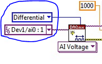
I use several USB 6009 units and with some of them seems to have some lag in differential mode, I with 0 to 1V range. Grounded the two terminals with resistors as shown in the tutorial OR «wiring field and noise review...» "seems to fix the problem for some of them, but for those that I have not the slightest compensation first, the ground gives me offset. Can someone please suggest?
Thank you
DS
DS,
Please submit your question in the Forums of NOR. Are you trying to take a differential measurement? What features are you try to measure it and what channels the drop-resistance work with and what channels do they not work with?
-
USB-6009 software simultaneous timed output analog
Ladies and gentlemen,
I worked on a LabVIEW interface to a potentiostat I designed and built. I'm not very experienced with LabVIEW, but do they have experience with a variety of other languages (I had originally intend to use an FPGA for this, but he has been asked to write a LabVIEW VI first) programming.
The goal:
I want to output a voltage (initially consisting of ramps) signal and measure the voltage with an operational amplifier configured as an ammeter of feedback (using resistance feedback and voltage value to calculate current) connected to an electrochemical cell. The resistance of feedback is selected by using an automatic selection function (although I wrote a version prior to manual control) as TTL values using the DAQ Assistant to select relevant MUX channel outputs. I then try to save the data in a spreadsheet.
The problem:
I use an acquisition of data USB-6009, and I know that there is a hardware clock. Read all about him seemed obvious, the best way to the waveform of the output voltage used DAQmx package to define a function of writing in a loop that is clocked by the software. The problem I have is that I can't synchronize the output to the input with reliability and I have also some errors related to resources DAQ being reserved (error 50103). I think the way to solve this would be to convert every equivalent DAQmx DAQ Assistant and try to group their execution - this is where I fall. I tried to write a simple VI who shared a loop clocked by the software to read and write but had problems related to the value of min HAVE (error 200077).
General issues:
How I begin the process of read/write (with a Boolean switch) is very weak and doesn't feel not robust. Ideally, I would like to some form of indicator to warn the user when the read/write process is running and when it ended.
My error handling is terrible, but I find no big thing to read about the basics.
I use only a sequence of no and I think I should have more.
Once I hit the beginning, VI requires the file name for the worksheet - at first, I was afraid that data would be entered correctly, but I think it's okay because the file is generated and then changed. It would be better if the user asked for the name of the file once completed the data collection.
Any suggestion or help would be greatly appreciated. Thank you in advance.
Sincere greetings,
Julius
The hardware supports timed 6009 entry analog. Even with the 1Samp mode, your code could be simplified with a single task and several channels (dev1\ai0:1). Then use Nchan 1Samp.
-
Problem: The differential mode, measure 1.4 V, USB-6009
Hello world
I am able to charge and discharge the two capacitors, individually.
I use the USB-6009;
Two capacitors, two charts, two analog inputs (AI0 +, AI01-) and (Al1 +, Ai1-);
I have configuredin differential mode; Ok
Problem:
When a capacitor is switched off, it measures 1.4 V
Try to correctly set the task - run the DAQ Assistant to create the task

Dev1/ao0 would be much better - Oh, and now that you take the wizard open-Do on the wiring diagram, it offers you

For the PREMIUM of 6009 task mode AI0 is + AI3 is - and you only reserve reserve explicitly AI0 (AI3 line is reserved by seleting the + line in the channel and the declairing it is differentiated)
And give the task/channel a significant name of "MyCap1Discharge" would be useful...
Now let's talk about your electrical engineering:
The input of the 6009 impedance is 144kOhms the resistance of discharge 1MOhm becomes useless as soon as you connect the control AI 6009.
-
acquisition of USB-6009 2 inputs
Hello
I currently use a usb-6009 with labview 7.1 and DAQmx 8.1 to read the data in a file LVM to a sampling rate of 40 kHz. Everything works perfectly when I read only one channel. Problem is that I have to read 3 channels and when I put the DAQ assist to read 2 channels, max sampling rate is 24kHz, which is not enough for the problem.
Then, I thought I could handle by reading just one channel at a time at 40 kHz (with digital input to determine which channel). Is this possible? When I put in place DAQ assistant with more channels, I can't select a sampling rate of 40 kHz. I know that you cannot open several DAQ assistant for analog inputs, so I tried to solve this problem by creating a main program with subroutines, each using a DAQ passes, but still got the error: "the specified resource is reserved. The operation could not be performed as indicated. ».
I tried to put in place without the DAQ Assistant, but had an error: specified is not valid or does not exist "(error code 200088) that seems to be a known an irreparable problem on labview 7.1." (also I guess I'm having the same error of the resource is reserved as I did in the DAQ assistant)
Is it possible that I can put in place a program to read an analog input to 40 kHz on a channel, and then switch to another channel and do the same thing?
Thank you
Herman
Of course, but you must stop and cancel the previous task before starting another. Obviously is that since you get this error.
-
Device USB-6009, not found problem
Hi all
So my VI and USB-6009 worked fine until recently. I noticed the VI was read or graphing correctly the analog input channel information. My firmware is up to date, but I noticed a problem. In Isdaq, he will recognize the USB-6009 case is connected, then when I start my VI and to stop it, I double check Isdaq for my device and it doesn't recognize any device. I have to unplug the daq and reconnect to Isdaq to recognize the usb-6009 case again. But whenever I start my VI, it does not collect all the data and makes the unrecognizable device. Do you know what could be the problem? Is attached the VI I ran in case you want to watch. Its working fine so far.
BTW, I'm under Labview on Mac OS X
Thanks for the help!
Hello Solis,
I recommend you to make changes to the parallel tasks to use the cluster of the error to force the order of execution, given that NEITHER-DAQmx Base is not multi-thread safe (review NOR-DAQmx Readme). Please check if this alleviates the problem.
Best regards
M Ali
Technical sales engineer
National Instruments
Maybe you are looking for
-
Drive cdrw/dvd satellite 1950 801
Where can I find a list of compatible cdrw/dvd player forMy Satellite 1950 801? Thank you
-
Re: Satellite L450D cannot remove file of office
Hi all, I was veiwing pictures on yahoo using firefox version 3 6 3 email sent by my sister in Australia, when this file appeared on my desk that I can't remove.The file is called Pez & Lisa (after my sister and a brother in laws photography) when I
-
My computer shows now all the money in euros, not dollars.
Today and for no reason that I can detect, my computer is now display of hotel rates, my bank deposits, all values of the money/currency in euros rather than dollars. I checked the settings on the computer and they are set to the American currency: d
-
The taskbar appears on the right side of the screen
my taskbar moved vertically to the right of the screen, how can I put back it?
-
BlackBerry storm 9530 camera smartphones
Is it possible to disable the sound of the click of the camera?