Analog input noise, best way to filter?
Hello
I use a cRIO (w / LV 8.5) to make a lever on an electric race car and the driver throttle control signals are 0 - 5V or 0-5kOhms. Now, I work with a signal of 0 - 5V for some tests. If this gas 0 - 5V input arrives, the cRIO resembles certain conditions, and if all goes well, just if he crosses this 0 - 5V located on the engine without changing it at all. So I have a NI 9201 AI module and a module NI 9263 AO. Our first hook this system up to a motor on our chassis dynamometer, however, we quickly realized that there too much noise in the signal of butterfly, and engine jerking around, kind of like he's possessed. We thought that maybe we could live with that, sort of like the irregular Growl, you get a burly V8, thinking that this might be nostalgic for the former riders, but it is a bit difficult for our lab tests pending.
I had a look at a few examples of using a lowpass butterworth filter on the FPGA, and this seems to be a nice implementation. My stumbling block comes from the fact that I use calibrated data, value engineering coming out of the modules and just passing the value of the voltage of my HAVE on area of OCCUPANCY. Meanwhile, the Butterworth filter can operate with integer values. I then tried affecting the entry and the exit of the modules of the raw data and not calibrated sends me data whole instead of FXP and then passing the entrance through the filter and then straight in the output module. It seemed to work at first, but then I realized that my exit was not mapping to my entry, the voltage output was far from what I was before. This is because the calibration of the raw data to engineering values is different for the two modules, and integer values, as I passed from one to the other do not match values of voltage. Then I thought that I could take in the raw data from the input module, filter it and then pass it through a calibration unit which become values of voltage, and send data to the output module calibrated (reset the rear output of Raw to calibrated, but keep the entrance of raw data.) That was when I realized the calibration of raw to engineering values, I've seen always happened in vi of the host, and that the calibration does not support the FPGA that blocks, I found in the examples.
I don't see how do now (maybe throw a gain to adjust the output data until my entry maps correctly to the output) but she think there must be a more legitimate way of filtering data from a module of HAVE and that passing on an AO module. Thank you in advance for your help!
Jeff
Hybrid of McGill Racing Team
I've backed a LabVIEW 8.5 project that shows an example of what you're trying to do. There is a test case of windows showing the result of the filter. I think this can help.
The analog input is 12 bits and the output is 16-bit, I'm sure that is part of the issues you dealt with that.
Tags: NI Hardware
Similar Questions
-
What is the best way to filter the records displayed in a DataGrid?
Hi all
I have a DataGrid that I use to show the records to a user. I want to give them a few boxes to filter the different criteria. For example, "hide/show has fallen members', ' see life only members", etc..
My first thought was to attach an event listener that fires each time that a checkbox is checked/unchecked. In addition, there an ArrayCollection 'original' collection that contains all of the records. Each time a checkbox is checked or unchecked, loop then on the 'original' ArrayCollection collection, creating a new collection ArrayCollection that has only the records you want, and then you bind the DataGrid to whom.
What is the right way to go on this subject?
-Josh
Instead of creating a new collection of arraycollection, use the FilterFunction function on the original arraycollection collection.
I have a simple component on the exchange of Flex that allows to filter out people based on text matching
http://www.Adobe.com/cfusion/exchange/index.cfm?event=extensionDetail&EXTID=1414018
You should be able to copy the logic and apply it to the boxes.
Thank you
Vackar
-
Best way to filter out VPN traffic
We set up a VPN tunnel with a vendor and I want to not allow Pings and a specific port. I thought you could do that through the card encryption on the ASA 5510 but looks it must allow all IP traffic, and then you filter by using a filter of VPN? Which requires a parameter default sysopt change. Don't I have that right? Am I overthinking this? My VPN tunnels are normally in other areas of society I want to all IP traffic.
Thank you!
Hello
No, they are not directly related to eachother.
You can use the VPN filter without touching the "sysopt" configuration.
Rather than configuring separate ACL (which uses a different logic depending on the format) for each VPN I prefer to put "no sysopt permit vpn connection" and filter incoming connections running through VPN connections on the 'external' ACL interface like any traffic coming from behind ' outside ' interface.
Here is the link to the information custom "sysopt".
http://www.Cisco.com/en/us/docs/security/ASA/command-reference/S21.html#wp1567918
Hope this helps
Remember to mark a reply as the answer if it answered your question.
Feel free to ask more if necessary.
-Jouni
-
What is the best way to Sync Output (TTL) digital with analog output?
I'm trying to generate analog signals that synchronize the rising edge of a digital signal (TTL). The ttl will be the trigger for the camera. The advice I have is USB-6343 X. In my project, I used a clock as a ttl so I can give frequency easily. Could someone tell me what is the best way to accomplish this task? My project seems to work, but I hope it has more neat way. Thanks in advance for any help!
Kind regards
Eric
Hi Econg,
They should be nanoseconds, if any, there is a trigger of material goes with a hardware clock.
-
What is the best way to get direct playback of audio input?
I know it must be easier that I am making, but somehow I can't seem to make it work right. I use a myDAQ taking into data analog voltage and eager to play back (with some filtering) through its built-in audio system taken or my computer. Seems to me do not understand exactly how the DAQmx voltage output is supposed to work; using anything else that the screw express so far just gave me errors. Using the express screw, I was able to taste and delayed reading data blocks, with spacings between them (not exactly ideal).
An example of code could greatly help to understand how this process should work and would be useful to many other people as well. Thank you.
I think that this example does exactly what you want. It supports analog input of the myDAQ, then has the ability to add a filter, and then she out back. I can't remember where I found it but it was in a workshop to learn how to use the myDAQ and LabVIEW.
-
Best way to reduce image noise?
Hey there,
I had some footage with an iso low light high and a bow flowing into it. What would be the best way to hide a bit? Thank you!
An excellent choice for denoising is a Neat video plug-in. https://www.neatvideo.com/
Have us use these jacks for years and are far superior to what we have seen so far. Check out the demo, you'll be amazed.
-
Analog input problems using PXI-6232
I tried to solve this problem for a while now without a bit of luck. Solution suggestions are welcome.
I use a PXI-6232 with LabView 8.5.1 to accept signals analog several of my sensors. Based on the signals as a PWM signal is generated and the output using PXI-6713.
Some of the analog input signals have spikes in them, which occur at all times during the tests. I watched the same signals on an oscilloscope - without crampons. I change my hardware configuration, and the spikes still occur in the same places. It seems that the program makes some resets resulting in measurement errors.
I have attached the VI and a JPEG of measured inputs.
Thanks in advance
Concerning
Vadim
I was first confused of your time scale
 but it seems that these spices occur every 20ms (not s) what to a line 50 Hz noise due to switching power converters (or a diode without compensation bridges
  )
)Another clue was the measure of the scope. While using the application scope, you opened a groundloop so the spikes because of the dI/DT through the groundloop are another way to get around.
So I'm pretty sure this isn't data acquisition (in this case) this is your configuration.
Provide a cleaning (low R AND L low) path of power (keep them close and twist slightly if possible), add a filter to down the dI/dt, identify the ground loops. (Use your scope with a little as a sensor at the entrance to reel and catch magnetic fields can open eyes)
THEN to clean the last ears (on the acquisition of data) to get the last ppm use selfs
-
Toggle the analog inputs and tasks of output on the same card in LabView
Hello
I'm relatively new to LabView and am trying to find the best way to switch between reading and writing tasks on my PCI-6024E. It seems this would be a common thing to do, but I found no good documentation or any relatable example program. Basically, I would like to be able to monitor certain analog inputs and then write that some outputs if an entry is in accordance with certain specific conditions (say > 4 Volts voltage). It is my understanding that you can only signal (input and output) types associated within a single task in DAQmx. I also understand that you cannot have multiple tasks running at the same time on the same material/map, otherwise you get a: 50103 error 'The specified resource is reserved. Calendar is not really all that matters to me, but quite synchronous and effective would be nice.
I have attached a sample program that shows more or less what I'm trying to do. I want to follow several analog input lines (AI0 AI1, AI2 and AI3 and) effectively at the same time. If certain conditions are met, AI3 > 4 Volts, then write 5 Volts for analog AO0 and AO1 outings. I also want to maintain output at 5 Volts up to AI3 falls below 4 Volts. Is there a better way to pass the task to read and write than what I've done here? In a sense, all I really do is toggle of a state machine if the required conditions are met and if start/stop tasks of reading/writing necessary.
One last question, is there a way to display the four channels in the waveform graph using the 1 d NChan 1Samp mode so I can have a time chart and indicators?
P.S. I'm under LabView 2011 on Windows 7. Your ideas and suggestions are appreciated.
Thank you
KJ
I also understand that you cannot have multiple tasks running at the same time on the same material/map, otherwise you get a: 50103 error 'The specified resource is reserved.
This is incorrect. You can't have two tasks of the same type running on a single card. You can have an analog input and analog output task running simultaneously on the same hardware.
You are right that each task can have only one type of task (entry or exit). Discover DAQmx examples in the example Finder to get examples of synchronized input and output.
PRO TIP: In the Finder of the example, go to the drop-down list in the lower left corner. Pull down and select Add Hardware. In the pop-up window, add your PCI-6024E to the right pane. Click OK in this window. Then in the main window of Finder example select your hardware from the drop-down list and check the filter results by the hardware. The example Finder then only you will show examples that are out-of-the-box compatible with your hardware. I am sure you can find something to fit your needs here.
-
iMac with Thunderbolt - how to get the old analog inputs
I hang up my old Mac Pro in 2005. I used it to record video cameras and mainly music best of my plate rotating and stereo system - vinyl and CD disks via s-video and RCA cables and Firewire for Mac Pro.
The iMac 27 "new is primary Thunderbolt and I can't find a Thunderbolt conversion box so I can enter my analog input RCA and S-video signals. No indication on the Thunderbolt converters 'both ways' I can't exit analog in the iMAC, then the iMac as well?
They certainly run Final Cut Pro X on the iMAC, then how people get their old media and music in the machine?
I'm about to talk to the local Apple store, but the chances of finding someone who knows what they are talking about with the iMac, Thunderbolt and analog input is going to be a stretch.
Al Donn
You can probably use a converter DV firewire as a Canopus ADVC 110 http://www.bhphotovideo.com/bnh/controller/home?O= & sku = 349146 & gclid = CLSF0_qUnswC FQ8vaQod9VkFFw & is = REG & ap = y & m = Y & c3api = 187... and then an adapter firewire-crush.
-
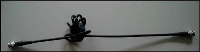
Several analog inputs seem to change any of the other (details DAQ: 2120 BNC and 6062E)
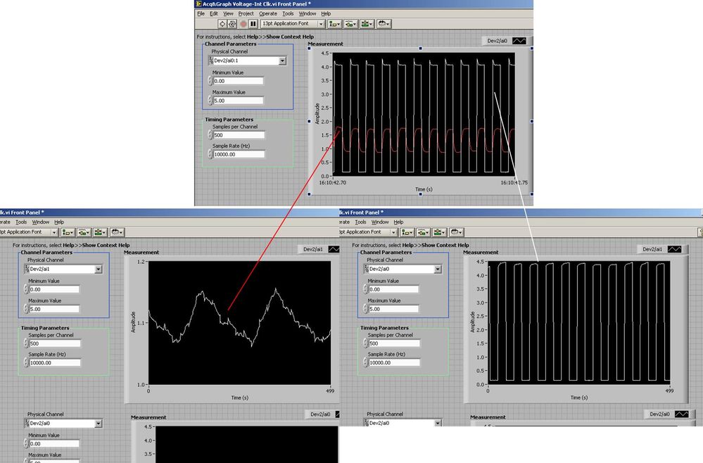
I use the BNC 2120 DAQ board connected to the data acquisition card 6062E to record two analog inputs. An entry is connected to ai0 and the other at ai1. Example vi: "Acq & graph int clk tension" has been used to measure the two entries with the value read NChan NSamp vi (channels being dev2 / ai0:1). The output is the top graph in the image. However, this seemed a bit strange to me that one of them should be modulating with a different frequency. When I record both entered individually (two in low pictures) they are indeed different since the entries shown in the top graph.

Why this would be the case, and how can I overcome this to measure the real signals?
Thank you!
The E series card takes the samples as soon as possible. Thus, for example,.
If you have 16 analog input channels but you only read of
channel 0 and 1, the map will show the channels 0 and 1 right
After and then wait 14 'ticks '. What's that little run-in
the origin of the afterglow.
I think you can get the card to wait a certain
number of ticks with a property node. I have attached a screenshot. You
can find the property node in the palette of functions >
Measurement of e/s > NOR-DAQmx > node Timing. Expand it
Property node so there's two entrances. The properties are in
Left click on the node and going more > converted >
Its properties delay units and sampling clock delay and delay that
you want.If the phase is important so the above is not the best
the option because it causes a delay in phase. So, if you need true simultaneous
sampling, then you will need different hardware. The S series is everything
simultaneous sampling.Or, rather than the Delay property and delay units, try the Rate property
find more > converted > rate.If this is not
work either, you can move the second signal source to, say, AI8 and
Connect everyone to the ground. Readings for these, but just do not take into account
the data. In this way the ADC will sag to the ground at the time where that can happen
the second string in the way so that you should not see this frequency
ghosting on the other channel. -
Problem with a precision of analog input on PCI-6111
Hello
I'm reading an analogue signal which varies from 0-11 V using a card of acquisition data PCI-6111. The signal comes from a Tube set (PMT) which is part of a microscope configuration, so it is very important that the resolution of the analog input signal be as wide as possible generate quality images. According to the data sheet for the PCI-6111, the analog input resolution is 12 bits, which should correspond to a sensitivity of ~2.686 mV for my voltage range.
To test this, I set up a task to analog input with a 0-11 V voltage range to read samples of an analog output, which I wrote a simple waveform. Since the 16-bit analog output resolution that I assumed that it would not limit the accuracy of this measurement. I have attached the VI I used for this measurement below. The analog input data are saved not truncated in a text file.
Analyzing these data, I found that the real input sensitivity is ~9.766 mV, corresponding to levels of voltage exactly 1126,4 and ~ 10 bits.
Is there a reason why the resolution of analog input is much lower that it is indicated on the card? What are some of the ways I could improve the sensitivity of this measure?
Best,
Keith
Sorry, when you mentioned the specs, I thought you already had them. If this did not come with your Board of Directors?
-
Hallo,
I use the following system:
- OR PXI-1044 with controller NI PXI-8109
- OR PXI-2564 switch module to turn on the monitor of my test device
- Data acquisition multifunction NI PXI-6259 to measure the signal that responded to the questionnaire jump
The two cards are the same - PXI trigger bus. For both, PXI-2564 and PXI-6259 I use DAQmx to set the reading and writing of the channels.
Now, I want to measure the time between the digital output, my unit turns and the analog input, which measures the response of my system.
I can't do work by myself, please help me!
I thank Ludwig.
Hi Ludwig,.
If you can't give us any VI we have difficulties with to help you.
Because I Donat knowledge how your program is mounted it is not easy to know where you should enter signals.
Here's a question similar to yours:
http://forums.NI.com/T5/LabVIEW/best-way-to-measure-time/TD-p/178704
and 2 external links:
http://www.ehow.com/how_8698983_measure-time-LabVIEW.html
http://objectmix.com/LabVIEW/385152-how-can-i-use-LabVIEW-measure-time-between-analog-pulses.html
-
USB-6211: analog input signal affecting another of the same map AI
Hello
I use the DAQ-nor-6211 map and DAQmx features to read a hammer and a signal of the accelerometer and then use other LabView functions to make the FFT of these analog input signals. However, it seems that the analog inputs where the hammer and the accelerometer are connected generate a kind of noise or influence in other entries of this data that is not connected to any other sensor acquisition board.
I've had different experiences in order to check if the problem is with reading the card: put the accelerometer and hit the dog in another table where the DAQ card table was located (to avoid the vibrations on the map and a possible noise), ai1 entry was logged on the differential mode on the dog and the ai4 of entry is connected to the output (z axis) of the accelerometer. The other 2 ai2 and ai3, entries that can also be read by my LabView program, are open (i. e., any other sensor is connected to the card). When the structure where the accelerometer is located is struck by the hammer, the signal of ai2 ("x axis" seen in the first attached document) has a curve (on the time domain) which initialize almost at the same time that the hammer and the a3 of entry has a weak signal, but with the swing as well as the signal of ai4. The document "hammer ai1 + z_axis connected_ _x_axis disconnected ai2 + y_axis ai3 ai4" images that I captured the chart created in LabView. On these graphs, it is possible to check on the FFT the ai3 signal and ai4 has the same behavior (with different intensities), and enlarged figure of time domain image, we can see that the signal of ai2 increase almost at the same time of the signal of the hammer (ai1). The signal picked up by the sensors are probably creating a sort of noise on open entries ai2 and ai3.
Another experiment was conducted to check if the signal from a single entry that may affect the signal read from each other near the entrances: the DAQmx task Create channel had a physical channel has changed: ai3 entry has been modified by ai7 (maintain the same connection mode: differential), and the results are visible on the second attached document. In the graphs obtained in this experiment, it seems that the entrance of the hammer (ai1) affects the signal of input ai2 and ai7, which are not connected. And the ai4 signal does not seem to influence the other inputs, because he has a different curve on the graph of the FFT.
The same experiment was conducted using the CSR connection (change threads and create the DAQmx Channel Configuration), but the results were the same as those found using differential connection.
Finally, if the output of the accelerometer is connected on the ai2, the signal of the other open entries ai4 and ai7 seem to be affected by the signal of the accelerometer on ai2 (last document attached).
Could you tell me if the problem I encounter is caused by the DAQ card with this information that I gave to you? And if the answer is Yes, do you know if there is a way to avoid this noise create in one entry on the other hand, it please?
Thank you
Maybe Ghosting or crosstalk? Just an idea.
-
Continually acquire analog input, internal clock, break, Multiple device
I have a PXI chassis with 6 cards SMU-6363. I want to acquire data on the channels of each SMU-6363 map continuous AI, using the internal clock for timing. I need to use a trigger to pause reading of a DI on one of the cards SMU-6363 for a break and to reactivate the acquisition. I came across this example: https://decibel.ni.com/content/docs/DOC-12256/ , but keep getting error-201019 DAQmx start task "trigger break is not supported in a task to more devices. To configure the start of break in a multi-device configuration, you must use no more than one device per task and route manually clock in demand signals. »
The problem is that the configuration of I is made during execution by the operator. Sometimes they want to acquire data on one HERE through all 6 cards SMU-6363, sometimes they want to acquire data on each channel of AI through all 6 cards SMU-6363. What makes the task definition until manually route clock signals between devices for each rather difficult task.
Is there a simpler way to solve this problem?
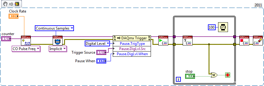
Set a task to output counter - something like this:
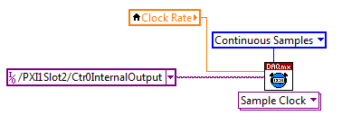
Next, configure your task of analog input to use the sample clock output of the meter:
Best regards
-
NI USB - 6212 BNC analog input impedance matching
I just ordered a case NOR USB - 6212 BNC DAQ (should be delivered soon). I want to use to measure HV signals using a probe of high voltage of 1/1000 I have.
Now, datasheet of the probe (not a lot of info) says it has an impedance imput 100MOhm. I suppose that it consists of a simple resisitve divider, and if the ratio is 1/1000, I wait so to have a 99.9MOhm resistance in series with a 0.1MOhm resistance. However, the data sheet also specify that the probe is designed to be connected to an oscilloscope with an impedance of 1MOhm. As this input impedance is very low compared to the low value of the separator of resistance resistance, so I guess that the real resistance at the level of the sensor values 99.9MOhm and 0.11MOhm (to obtain the 0.99 and 0.1MOhm when it is connected to the oscilloscope for 1mW).
Therefore, given that the impedance of the USB-6212 according to the datasheet, the analog input is > 10GOhm, I expect to measure higher to true alternative voltages when connected to the acquisition of data from 10%. This assumption has a meaning?
What would be the best way to get around this? Do a calibration and correct the values acquired in LabVIEW code? Or should I add precision 1MOhm resistance at the same time to the acquisition of input data to decrease its resistance to entry to the value expected by the probe?
Thanks for your help!
Since you have a range of 1000: 1 I guess you also need bandwidth (I have a TEK 6015 A
 ), so you need based on the impedance input, a complex value, means he must not only watch but also the ability to input resistance (1 M). demarcation of the field probes have usually some elements of toppings to match the probe and the input scope. RTFM of the help of the probe
BUT a more serious point is that with your probe, you have a very high resistance. And if you look in the specification of the 6212 you will find on page 2 by mistake ppm in logarithmic scale graph! and even 100 k source impedance it not shown.
So I'm afraid that a simple 1 M on the DAQ entry can work if you're only measuring DC, and only if you use a channel on the acquisition of data. A workaround is an amplifier separate buffer with an impedance of good entry corresponding to the specification of your probe and a low output impedance.
Maybe you are looking for
-
How to write responses to several e-mails and then send them all once I've finished?
think it would save time rather than waiting for each to send individually
-
Re: Lost shortcuts Toshiba FN + F1... F12
I reinstalled my Win7.Now, I've lost all my shortcuts on Toshiba FN + F1... F12. How can I reactivate them?
-
Problem with the play, pause, stop buttons etc on Satellite M30 842
I have tried pretty much everything I can to get these buttons to work, but it seems that their just their for pleasure. any suggestions? I also wonder if anyone knows if it is possible to download the drivers for the sd card reader able to read card
-
"out of paper"... BUT it is not
My printer says "on paper." I had just copied something and it was very good. Went to copy something else and He said "out of paper". It is out of paper. I tried to take the paper, put again, etc. I tried to turn off the printer and the fact to unplu
-
Save the waveform output to a text file when VI runs continuously?
How can I save waveform output to a text file when I start my VI permanently? I do power profiling and you want to save voltage drop measures continuely.