Strange analog output of USB-6211
I just got USB-6211 to replace USB-6001 to set the clock to external sampling on analog output for LED lighting control. The part of external clock example works fine, but the analog output voltage is strange. To do self-monitoring, I connected control pin LED to AO0 & AI0 of surveillance in the NI MAX test panel and LED control on the ground at AO - GND & GND HAVE since I have both USB-6001 and USB-6211, I conducted tests on two of them with the same setting of wire. When I generate sine wave - 5V to 5V to AO0 (from NI MAX test panel), USB-6001 can monitor the same signal AI0, but watch USB-6211 - 3, 4V to 3.4V voltage truncated. I did the test separately (wiring one device at a time), so there is no interference between the two devices. USB-6211 past self-calibration and self-monitoring. Also, I did reset devices. I don't know why they would behave differently with the same configuration, and I hope that someone could help with this question. Thank you.
Hi skuo1008,
The USB-6001 can support + / 5 output current my from terminals to analog output, while the USB-6211 box can provide only +/-2 my current output. It is likely that the load impedance is too low, causing the 6211 to hit its current compliance and thus cut the tension. If you try to exchange your load with a resistance of at least 5 v/.002A = 2500 Ohms, you should be able to see the full +/-5V sine wave. I suspect that your DUT has a words 3.4V/.002A = 1700 Ohms impedance. You could use a device with higher output current or use a more current source buffer circuit. If you do not need a bipolar output, you might also consider using digital lines to control the LEDs.
Kind regards
Tags: NI Hardware
Similar Questions
-
Current limit for analog output on USB-6211-OEM
The current output drive listed in the specifications of this card is of +/-2 my. What happens when you try to go beyond that? Is there damage to the card or is it simply rail out around 2mA. For example, if I connect a 1000 ohm load. I'm okay, if I have the output up to 2V (= 2mA), but what happens when I exit 3V with the same 1000 ohm load?
Thank you.
Protection of the overdrive is 2.4 mA, which means that you can ride this current without damaging the card, but a current of approximately 2 mA, tension is more guaranteed to be compliant to the specifications.
Kind regards
Brian P
-
Digital magnification of output using USB-6211
Hello
I'm trying to use the example of LV "Cont writing dig port - Int clk.vi" to generate a model.
But I get the error-200077 on the sample clock. The popup error message suggests
using "we demand", but it doesn't have the choice with the DAQmx.
Any clue? Thank you.
It is correct. USB-6211 case doesn't have a digital time - analog base only. That's why the (63xx) X series cards are supported only for this example.
-
Reconciliation of analog output NI USB-6210
Using Labview, I am currently using an NI USB-6210 to produce a signal that a BOP of Kepco 50-2 M feeding programs. Unfortunately, this device NOR produced no analog voltage. Is it possible that I can use the digital output or against the unit OR to do something that approximates an analog output? I need a way to get the power output voltage has the supply to increase gradually in a predefined way. I only work with a couple of volts because of sensitive equipment, so accuracy is important.
I don't have access to the program at the moment so I don't know what version of Labview that I use, but I'll be able to check in a few hours.
Its probably not worth to use this device in a method not scheduled. Cheeper with analog outputs are available.
And don't forget the 4886 BIT card that can be purchased and hooked to your diet, there are even for using RS232 or GPIB device drivers to control the supply to
-
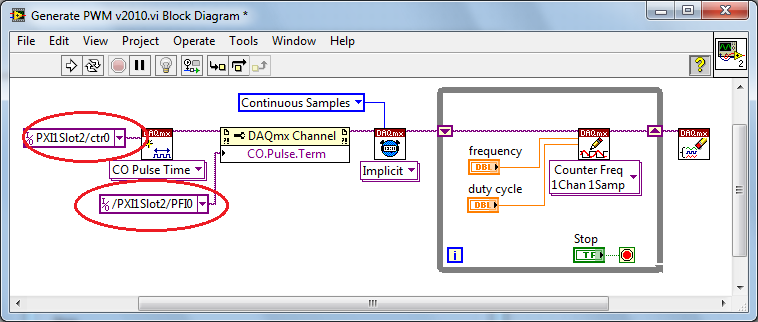
PWM - output meter (PFI4) USB-6211
I managed to control a motor based on PWM signal output via USB-6211 AO continuous. Now, I'm trying to use the Terminal counter instead.
Can't seem to make it work. NA not get a signal when link the PFI4 terminal to an oscilloscope.
I don't know wheather my coding is wrong or does not have my wiring (i.e. of USB-6211 for motor continuous). I need to use the terminal of meter that I used the analog output to a different measure.
Please advice. Attached encodings.
Thank you very much.
Front of conneting to DC motor, make sure first that the PWM is get generated correctly... use oscilloscope.
And have you changed the constant (physical terminals) for your device...?
Change to:
Dev1/ctr0 & Dev1/PFI4 and the scheme of connection must be:
-
Sampling frequency for the output of an acquisition of data USB-6211 card?
Hello-
I use a CGI CMOS FireWire camera to read an interference figure, then using a transformed of Fourier transform spectral interferometery (FTSI) phase recovery simple algorithm to detect the relative phase between the successive shots. My camera has a linear 28 kHz scan rate, and I programmed my phase retrieval algorithm take ms ~0.7 (of a trigger of camera at the exit of the phase). I use the live signal to control a piezoelectric stack, by sending a voltage single sample to the analog output of a data USB-6211 acquisition card.
Send this output voltage increases the time of my loop 4 m, I would really like to achieve a 1 kHz or better sampling rate. Is the problem with my DAQ card or with the processor in my computer? The DAQ cards of NOR can support these speeds?
Thank you
-Mike Chini
Hey Mike,
With USB, your loop rate will be around or under 1 kHz, even on the best of the systems. USB has a higher latency and less determism PCI and PCIe. You can get rates AO one much better sample on a PCI card, potentially a PCI-6221. We have a few HAVE points of reference for targets of RT for PCI, / AO in a loop, you should be able to get similar performance in Windows, but if you do a lot other treatments may suffer from your local loop rates.
Hope this helps,
Andrew S
-
Incorrect value for analog output USB-6008. Cannot not out more than 3V
I use USB-6008 analog IO, but the analog output (AO0 or AO1) can go up to 3 - 3.5V. The output can follow accurately the value of 0 to 2, 5V, but then he start the values adjusted trolling and not can not spend you 3.5V exponentially.
The only strange thing the entire circuit is that I connected all patterns (analog source and I/O 5V) between them, but I don't see what affect the output.
Kind regards
ISSOKO
Thanks for the quick reply Ana.
It is not the Council NOR, nor the Council of motorization. Apparently, the interface for motor control (motor spirit C: solutions - cubed.com), load the analog output. A tension following actually isolated op amp output USB-6008 and solved the problem.
Best regards, ISSOKO
-
USB-6211 - digital output not supported?
Hi all
I can't use the USB6211 device port... I use daqmx with Delphi7 API functions.
First of all, I tried this:
DAQmxCreateTask('', @TaskDO);
DAQmxCreateDOChan (TaskDO, PChar('Dev1/port0'), ", DAQmx_Val_ChanForAllLines);
DAQmxWriteDigitalU8 (TaskDO, 1, 1, 1, DAQmx_Val_GroupByChannel, $FF, @written, nil);I had an error in the DAQmxWriteDigitalU8:-200012 (= digital output not supported). (???)
OK, I tried to disable autostart option based on DAQmxWriteDigitalU8 and insert a 'manual' start in the code:
DAQmxCreateTask('', @TaskDO);
DAQmxCreateDOChan (TaskDO, PChar('Dev1/port0'), ", DAQmx_Val_ChanForAllLines);
DAQmxStartTask (TaskDO);
DAQmxWriteDigitalU8 (TaskDO, 1, 0, 1, DAQmx_Val_GroupByChannel, $FF, @written, nil);
DAQmxStopTask (TaskDO);Now, I got the same error in DAQmxStartTask:-200012 (Digital Output not supported, once again). (?????)
I don't understand.. 'Digital output not supported "? USB-6211 has 4 lines! What is the problem?
I want to just turn on and off the lines from code...
-Cs George-
Well, finally I figured out...

Here is the solution:
DAQmxCreateTask('', @TaskDO);
DAQmxCreateDOChan (TaskDO, PChar('Dev1/port1'), ", DAQmx_Val_ChanForAllLines);
DAQmxWriteDigitalU8 (TaskDO, 1, @dummy, 1, DAQmx_Val_GroupByChannel, @bitmask, @written, nil);Digital output lines are on port1! Corrected parameter.
And the part of the interface of DAQmxWriteDigitalU8 had to be changed (in nidaqmx.pas).
I don't know why, but the AutoStart (dummy) parameter in the DAQmxWriteDigitalU8 function is ignored: function always starts task automatically, regardless of the value of autostart. But this isn't a problem for me.-Cs George-
-
Simple examples of analog output USB-6343
I've tried passing by 'find' examples and does not know how to find what I want.
I'm doing a simple analog output on a USB-6343. Examples of waveforms say they work with the USB-6343, but I really don't want a waveform, just analog of output does not exceed 10 Hz speed of renewal. Some of the more simple examples show that they work with the pcie-6343 but do not list USB-6343.
I worked with USB-6009 in the past, but when I try to use an analog output task that uses 1 sample on request, I get the error "not buffered operations clocked by the hardware are not supported for device and channel type.» Set the size of greater than 0 buffer, do not set up the timing of the sample clock or the value Type of sample On Demand time"
I tried samples N, 100 samples to write to 10 Hz - the same error. Samples of continuous - same error. 1-sample - timed HW - same error.
There is a series of examples of I/O for the X series? Is it possible to search the device examples rather than go through all the examples and by checking the list of devices individually?
Is 'size of the buffer' the 'writing samples"in MAX?
After contacting the support I was provided with the names of the more simple examples for analog i/o:
Analog output-Gen power Update.vi
Analog Input-Acq & chart voltage-Int Clk.vi
They are found in the getting started screen of
Click 'Find examples' near the lower right corner
Filter the results to material by clicking on the menu drop down for the material in the lower left corner and selecting USB-6343 (only connected equipment will be displayed)
Don't forget to check the box "limit results to material" below.
In the center pane, double-click 'Material Input and Output'
Double-click DAQmx
Path for the analog input - double-click Acq & chart analog measures - double click on tension - tension-Int Clk.vi
Double click on analog generation - double click on Power - Gen Update.vi of analog channel output voltage
The examples are for the single data point. Samples and exit multiples are produced by putting the writing or reading VI inside a loop. The beginning and the clear functions should be out of the loop.
Additional information, I need technical support was how material-filter results and identification of more simple examples which were not obvious from the examples of names.
-
To write a waveform to two outputs analog of DAQ(USB-6215)
Hello
I use USB-6215, who has two analog outputs and having to send the same waveform through the analog outputs two of my DAQ. at the same time. in fact, I have a text file consisting of a code word (please see the attatchment) with dt, freq and annex 0 in the first column and other columns contain the word coded. Withe the help of dt, the rate and the data I did a waveform with the wave of construction VI. I am able to write this wavefrom through an analog output A01 right now. I want to know how I could write the same analog waveform other AO0 out simultaneously. I use a source of external triggering via PFI0 to be triggered. for now, I use the write.vi DAQmx (analog channel 1 DBL 1 d N samples) and DAQmx create virtual channel.vi with dev1/ao1 as the physical channel. For more information, I am attatching the program along with the text file. Please see page 2 of my structure of matter in the VI attatched.
Thank you.
Kind regards
Raja
Hi Steve,.
his works now. I changed the instance of writing DAQmx for analog waveform samples N channel N. still, I now that a single waveform. How could I do like two like it (writing DAQmx) will not accept a single waveform as the entry as the number of channels in the task will now be 2 where, under the waveform has an exit.
Kind regards
Raja
-
Strange problem with analog output PCI 6251 and BNC-2110
I'm controlling current source of third parties using the connectors of analog output on my card PCI 6251 and BNC-2110.
The current source needs an input signal of 0.1V. I tested it using a battery, the potentiometer and the voltmeter, and by manually adjusting the voltage of power current works - current output with control voltage scales according to the specifications and is relatively stable.
The data acquisition card works too - when I connect a voltmeter to the AO0 AO1, the measured voltage corresponds to the target with great precision value.
But when I connect the current source of third AO0 AO1 data acquisition card, the measured output voltage drops and fluctuates. This applies to both channels of the AO.
I wonder what is the problem here. I suspect it could be a matter of the grounding - the current analog control of the source is an entry with two floating terminals differential. I tried to return the switches FS/GS on the BNC-2110, but that makes no difference.
Anyone knows similar behavior? Does anyone have any suggestions?
-
How can I check if the counter entry is synchronized with the analog output?
Hello
I'm working on an application for counting photons. I use two channels of analog output on a PCI-6713 card to send a frame model to a set of XY scan mirrors. I then a photon count unit that emits a TTL signal when the photons are detected as a result of this raster analysis. I then use a surfboard USB-6211 to count the edges on this TTL signal.
I have problems that seem due to synchronization problems. I use the sample AO on the PCI-6713 card clock like the door of my meter on the map USB-6211. I use a trigger to start digital to analog output and a trigger of arms for the entrance to counter early. Is there a way to check that the analog output and counter entry of start of operations at the same time and are are synchronized? I basically want to monitor and compare the ao real sample of the PCI-6713 card clock door signal used by the jury of the USB-6211. I was able to export the sample AO clock and watch it on my oscilloscope, but not the signal from the door of the USB-6211.
Thanks for your help,
Brian
Update... It turns out that there is no problem of synchronization between my meter input and the analogue output. There was a difference of impedance when I connected my unit of counting photons to my USB-6211. This caused an error variable count rate. After accouting for this shift, the problem disappeared.
-
Redeclenchables/continuous to a custom waveform analog output?
Hello
I try regular output an analog signal using the box USB-6211 and Labview2009. I looked at various examples of waveform, including the retriggerableAO.vi example, but I can't seem to understand how to send a 'waveform' custom stamp (terminology is perhaps the question). In all the examples (including waveformbuffer), I ran across the single waveform, the options are sine, square, etc. Previously, I posted on this forum looking for hardware suggestions (link here) and explained what I try to do and got the big help. To sum up, I would like to read a 'waveform' from a text file, send it to the usb-6211 buffer and then continue to an analog channel. At the same time, I'll use the beginning of the analog task to trigger a digital signal once per cycle as well.
I got in what concerns the establishment of the waveform, but am stuck to figure out how to get into the buffer and setting the frequency, etc.
Thank you
Gabe
Hi Gabe,
Dennis is correct that it will take some room to modify the existing screws to fit your need. As he says, the Con Gen tension Wfm - Int Regeneration.vi Clk - no example provided with LabVIEW. In the example, it can be shown that there is a custom VI used to explain the problems that arise when a waveform of a given frequency to a frequency of sampling and outputs analog specified.
With all that said, it seems you want to read from an existing waveform file that you created and this waveform to an AO output channel. There are a few things that will be needed to know before proceeding:
-What is the waveform as you try to output (5000 samples, 10 k, 100 k, etc.)?
-What pieces of the size of the wave you want output (100 samples at a time, etc.)?
-you want to again and again, or simply run through once the waveform looping?
Assuming that you already have the waveform and will only step by step, here's what I would like:
-break the large waveform into smaller pieces of waveform of standard size
-import the waveforms in LabVIEW and create an array of waveforms
-bring the waveform in the example Dennis mentioned previously with automatic indexing enabled on the tunnel
-Remove the generator of wave functions existing the while loop
-wire your indexed table of waveform for the data of the VI DAQmx of analog output terminal
It is possible that you will have to play with the settings of your waveform and timing of your VI, but this should be a good starting point. Please let me know if something is not clear or if I have misunderstood your original message. Have a beautiful reast of the day.
Best,
-
Lack of charges, USB-6211 with linear gauge Mitutoyo (542 series)
I use a USB-6211 box with a race of 10mm Mitutoyo Linear Gage (542 series, model LGA-110). The Mitutoyo has output similar to an encoder without the time by rev signal quadrature. (B has a phase shift of 90 degrees of A). Signals A and B are airline pilots. I have a k 2 5V to A resistance and another 2K to 5V to B, gives me a minimum of 0.05v and a maximum of 4.75V.
The problem I encounter is that I seem to be missing certain counts that I can't always zero.
I found that if I caress the complete range of meter and the return to zero in 20 seconds, I get a value close to 180 meter microphone. If I press the complete range of meter and the return to zero quickly in a second, I get a value close to 800 micrometer.
If I caress the quick pledge on the compression and rebound more slowly, I find myself with a positive value. I caress the slow pledge on compression and quick on the rebound, I find myself with a negative value.
As I said before, it seems miss me certain counts. With a pulse of each mic of 4 meters, it means I get only 2500 pulses per 10mm. This means that 10mm per second is only 2500 pulses per second. It seems slow for me, so I don't know what would be the problem.
Does anyone have ideas for me to try?
With this type of signal you should not missing any counts. The time base on the box USB-6211 is 80 Mhz and therefore should have no problem to solve your two pulses per train. I have a couple of steps that I would like you to try troubleshooting.
1 to ensure that we plugged the inputs correctly to our DAQ hardware.
2 ensures that we use both the non-reversed or two signals reversed. Do NOT mix or 'type' of the signal.
3 allows you to wire signals A and B in two inputs analog and we will try to read signals to ensure that the sensor is actually be set correctly by the sensor. Be sure to taste pretty quickly--> 10 the frequency of the pulse train. If you race through 10 mm in 1 sec--> 2500 pulses per second--> 25 kHz sampling rate. Allows to check two things. First we have a good TTL signals, and that we get the right number of charges. If you reply to this thread plaese attach a screenshot of the present.
4. we will try different encoder types x 1, x 2, x 4 in the DAQ assistant. The x 2 and x 4 encoder allows the best sensitivity for small movements (which I'm not sure that it is the source of your proplem but it will be a good thing to check). Types of encoder are discussed in more detail in the following developer area: quadrature encoder measures: How To?
Let us know how it shapes to the top.
-
Analog output of signal generation custom
Hello
I have a VI that generates a signal from the values in an excel worksheet. I'm trying this waveform through an acquisition of output data. I use a box NI USB-6211.
I copied the exit code for the acquisition of data from other VI that generates a sinusoidal signal coming from an excel worksheet. This program works very well. (attached for reference - Analog Output VI + sinusoidal waveform)
I have two problems at the moment. First of all, I get error-200560 about waiting until the function, attached.
Second output amounts only to about 5.5 v instead of 9V specified in the data.
My VI generate several types of waveform according to selected tests, but I'm trying to get an output DAQ working with the first test, named "disconnection of the battery" work first before implementing it in the other tests so please ignore others for now. To run this battery select VI disconnect under tests select then direct to the attached excel (BD values under 10V) file.
I hope that I myself have pretty much explained, otherwise please ask for more! I'm new to LabVIEW so your help would be very appreciated.
Thank you very much
Parker
aeParker wrote:
I've made a few improvements to the VI but I always feel the DAQ 5 Cap output, 5V.
Dear Parker,
I guess that this statement is based on the values in the chart show, AO 0. However, this is not (necessarily) the voltage produced by AO 0, but rather the tension being sampled by AI0. If you look at the DAQmx create channel for the AI voltage channel, you will see that you have left entries Maximum and Minimum Value unwired, which means that they take their values default to + 5v and - 5v. This may explain the behavior of cutting that you observe. Try the + 10 and -10 wiring and see if that solves this problem.
Bob Schor
Maybe you are looking for
-
I have the 10.6.8 OS on my Macbook (2.4 ghz intel core 2 duo with 4 gb 1067 MHZ DDR3 memory.) The model Macbook identifier 7.1) and I would like to upgrade but not sure where to go from here. A link to my next logical update would be greatly apprecia
-
best way to remove Norton from my IMac
I want to remove Norton from my Mac. What is the best way to do it. I will download another anti virus application.
-
Pavilion DV6-2010EQ: unknown device in my laptop DV6
I have an unknown device which can not find the drivers for Windows. I can't figure out what it could be. The most peripheral "exotic", as the receiver IR remote, are already installed and things seem to work as usual on my computer. The device is li
-
Camcorder LEGRIA HF - G30 with WD-H58W lens compatibility.
Hi all, I own a camcorder Legria HF - G10 with a converter WD-H58W wide-angle lens. Now, I want to change my cam with the Legria HF - new G30. Will I can continue using the WD-H58W camcorder HF - G30 or I have to buy the lens of WA - H58 as suggested
-
I reloaded windows. Cannot get screensaver to work.