Analog output PCI-6251-DAQ-200016 memory overflow error
NI PCI - 6251 DAQmx, AIMD-752 motherboard, dual core processor, a lot of speed and the ram running WinXP Pro & LabWindows/CVI
get DAQ-200016 memory overflow error when I try to generate a signal of analog output with a rate higher than about 32 000 samples/second (?)
going on what? I have never seen it before. Is this a problem with the motherboard? "It's the same product on the CVI code example" \Cont Gen Volt Wfm - Int Clk\ContGen - IntClk.cws.
If someone has had this problem, and is there a solution?
Thank you
PS: full text of the message reads:
Measurements: On-board memory precision passing. Due to the limitations of system and/or the bandwidth of the bus, the driver could not write data to the device fast enough to track the rate of output of the device. Reduce your sampling rate, change the method of transfer of data (from interruptions on DMA), use a product with more on-board memory or reduce the number of programs that your computer runs simultaneously. Task name: _unnamedTask<1> Code of State:-200016
Well, I found my answer. For later use, Olivia NI Apps Engineering suggested I have change the mechanism of data transfer by this Knowledge Base document:
http://digital.NI.com/public.nsf/WebSearch/C326F7D33CA6DB0E86256DFE008043B7?OpenDocument
... so I inserted the line of code between the creation of the area of OCCUPANCY of the channels and set up the example of clock calendar.
DAQmxCreateAOVoltageChan( ...

DAQmxSetAODataXferMech(TaskHandle,chan,DAQmx_Val_Interrupts);

DAQmxCfgSampClkTiming(...
now, I am able to generate output to a 2.35 MS/sec... max sampling frequency not quite the 2.86MS / sec indicated in the specification 6251, but close enough that I'll stop complaining

Tags: NI Hardware
Similar Questions
-
Strange problem with analog output PCI 6251 and BNC-2110
I'm controlling current source of third parties using the connectors of analog output on my card PCI 6251 and BNC-2110.
The current source needs an input signal of 0.1V. I tested it using a battery, the potentiometer and the voltmeter, and by manually adjusting the voltage of power current works - current output with control voltage scales according to the specifications and is relatively stable.
The data acquisition card works too - when I connect a voltmeter to the AO0 AO1, the measured voltage corresponds to the target with great precision value.
But when I connect the current source of third AO0 AO1 data acquisition card, the measured output voltage drops and fluctuates. This applies to both channels of the AO.
I wonder what is the problem here. I suspect it could be a matter of the grounding - the current analog control of the source is an entry with two floating terminals differential. I tried to return the switches FS/GS on the BNC-2110, but that makes no difference.
Anyone knows similar behavior? Does anyone have any suggestions?
-
analog input PCI-6251, implemented
Hi all
Can I set the analog inputs of the PCI-6251 in configuration of mix (some in differential mode) and others in single ended mode. Because in my set up the differential option is grayed out.
Thank you
dphan128
Yes, you should be able to do. You have 16 analog inputs. Differential, you will use two of them per channel. See the manual of series DAQ M. you can program channels on a M Series device to acquire with different
reference to the ground. To allow m
ultimode sweep in LabVIEW, use OR-DAQmx create
Virtual channel.VI of the API OR-DAQmx. You must use a new VI for
each channel or group of channels configured in another mode of entry.
Don't forget that for a premium that you would for example wire HAVE 0 to the + side and AI 8 - side. So now you can not use the AI 8 for simple nerve. HAVE 1 corresponds to the AI 9 etc. until 7 AM, GOT 16.
I hope this helps.
-
From recovery, I got this error message... "CDBOOT:MEMORY OVERFLOW ERROR."
HP G71-340US NOTEBOOK P/N VM114UA #ABA
New hard drive to factory reset the drive recovery for Windows 7 / 64-bit
WD 750 GB SATA 5400 RPM 8 MB
Message after installing the new drive hard and insert recovery disc one
Why have I not this error message?
Restarted laptop (several times), you press 'ESC' to start menu, F11 selected to start recovery disc, 3rd time charm, selected "Factory Reset" and follow the signs for "recovery with Image Preparation. Now in the process of "reformat the Windows Partition of your hard drive"...
I did something wrong? Are there future concerns with this overflow error memory cdboot?
Hello:
Sometimes the recovery disks do not work. It could be anything.
I have a workaround if you can still read the product key of Windows 7 on the sticker COST Microsoft to 25 characters on the bottom of your laptop.
If your laptop comes with Windows 7 and you can read the product key 25 character that you can download single files Windows 7 ISO to burn it to DVD for the version of windows (Pro, home) that are installed on your PC, and which is listed on the sticker COST Microsoft on the bottom of your laptop.
You must also select the language installation provided with your PC, or the product key will not work.
Burn the ISO with the option to burn the ISO on your DVD burning program and burn it at the slowest possible speed that will allow your program.
Use the product key 25 character on the bottom of the laptop to activate the installation.
Then go to the support page and drivers for your laptop computer install the drivers you need.
Link to downloads ISO of W7 is below.
http://www.mydigitallife.info/official-Windows-7-SP1-ISO-from-Digital-River/
Paul
-
Output TTL triggers analog input with PCI-6251
Hello, I'm new to LabVIEW and have a question that I hope I can get a response on this forum. I am currently using a PCI-6251 DAQ card with a block of connection BNC-2120. I would like raise an event on an input, for example a sine wave, which is connected to AI0 analog. Then I would send a TTL pulse train via the digital output. What I'm describing can be better understood by the images of this link:
http://zone.NI.com/DevZone/CDA/tut/p/ID/3017
In the tutorial page linked above, they do mention the card PCI-6251, but when I read the specs and compared, 6251 also has analog and digital Board, trigger functions, as well as digital I / Os... so I think he should be able to do what I want it to do. Can anyone confirm this? If anyone could help me by providing a VI that could do what I ask, just to help me get started, would be greatly appreciated. Thank you!
Hello!
Please post on the Forums OR! My suggestion would be to use build it digital Pulse - Retriggerable.vi found in the Finder for example of OR. Open LabVIEW, go to help > find examples > input/output equipment > DAmx > generating digital pulses > generate digital Pulse-redeclenchables. Change the type of trigger for this departure vi > Analog edge and make the source one line APFI (pin 20 of your card is APFI0). This will generate a pulse based on an edge similar to a level that you specify.
I hope this helps!
-
Entered analog PCI 6251 not extent of tension of a mass flow controller
Hey,.
I have a data PCI 6251 M acquisition with a break in Council SCXI 1302.
I'm trying to measure a 0 - 5v analogue output voltage from a mass flow controller (check picture of PIN)
When I measured with a digital multimeter the voltage of the flow signal (PIN2) and common signal (PIN12) I get a stable right tension between 0 and 5v depending on the flow set up. I can control the amount of the charge by providing a data output set point PIN8 and common PIN12 of the 0 - 5V analog signal.
Now when I connect the signal flow PIN2 and on my DAQ signal common PIN12 AI and AIGND, I don't get readings on my labview VI of the AI. In addition the flow does not meet the setpoint voltage, it get stuck in a range of values no matter how I vary the OD 0 - 5V of data acquisition in setpoint PIN8 and PIN12 common signals.
I have to add that I tried different ports HAVE with results of sam, and I also tried to measure my supply voltage with my HAVE and all the good work.
It seems that the entry of AI affects the AO output voltages to my charge. What would cause this? That would be a problem of impedance adaptation?
Management or ideas are appreciated.
Thank you
Ali T.
Update for anyone that might interest you:
I not connected to the ground of the power of the mass of the signal of FJA FJA.
Once I did the acquisition of data reads all data as expected.
So it turns out not to be a problem of acquisition of data, OR at all, but a game of question for my part, as I suspect is the case with most of the problems.
Jeff Merci for your comments.
Ali T.
-
I use the outgoing/incoming analog DDK with the DAQ 6341 SMU map.
The examples, for example aoex5, show a single timer (method outTimerHelper::loadUI), but the example shows the DMA loaded with same size of vector data.
There is a comment in the outTimerHelper:
 call rogramUpdateCount, which implies that memory sizes different pad per channel can be used.
(the comment is: switching between the sizes of the various buffers is not used)
Nobody knows what should be the format the DMA buffer for data from multiple channels with different frequencies?
For example, we want a0 with a sinusoid at 1 kHz and a1 with a sine wave of 1.5 Khz. What looks like the DMA buffer?
With the same frequency for each channel, the data are interleaved, for example (ao0 #0, ao1 #0; ao0 ao1 #1, #1,...), but when the frequencies for each channel is different, what the stamp looks like?
Hello Kenstern,
Data are always intertwined since each card has only a single timing for each subsystem engine.
To AO, you must specify the number of samples that will be released to the AO. You also specify the number of channels. Because he didn't is that a single engine timing for AO, each AO will be channel will be updated at the same time to update clock tick. Data will be interlaced exactly as shown in the example because each channel AO needs output at each tick of the clock to update. The data itself can change depending on the frequency you want to copy.
kenstern wrote:
For example, we want a0 with a sinusoid at 1 kHz and a1 with a sine wave of 1.5 Khz. What looks like the DMA buffer?
With the same frequency for each channel, the data are interleaved, for example (ao0 #0, ao1 #0; ao0 ao1 #1, #1,...), but when the frequencies for each channel is different, what the stamp looks like?
In your example, you must come with an update rate that works for the two waveforms (sine waves of 1 and 1.5 KHz). To get a good representation of a sine wave, you need to update more than 10 x faster than your fastest frequency... I would recommend x 100 if possible.
Update frequency: 150 KHz
Channels: 2
Then create you stamps that include complete cycles of each wave you want to produce based on the frequency of update. These buffers must also be of the same size.
Buffer 1: Contains data for the sine wave of 1 KHz, 300 points 2 cycles of sine wave
Buffer 2: Contains data for the sine wave of 1.5 KHz, 300 points, 3 cycles of sine wave
You can Interleave them as before. When the data are performed through the ADC, they are out different sine waves, even if the AO channels are updated at the same speed.
-
DAQ product with +/-analog output 12V?
We are looking to update a manual test area.
We are looking for a product DAQ with analog outputs capable of +/-12V
We are not generating waveforms. Just using LabVIEW to a tension he set in the range of - 12V and + 12V.
OR anything with this ability he selling?
I found the NI PCI-6703 and would serve our needs except that it is +/-10V.
Good morning New York,
Consider the SMU-4322 or NI 9269. The SMU-4322 supports + / 16V by channel. The NI 9269 has 4 (+/-10V) channels that can be cascaded for isolated older tensions.
Kind regards
Izzy O.
Product Support Engineer
NI.com/support
-
Blocking of blue screen with the analog voltage (WinXP, PCI-6251)
Hello
I'm looking to solve a problem of blue screen with my measure blocking
application, which I am developing with C++. Blocking seems manifest
a little random after a variable amount (500-50 000) of voltage analog
measures. My application needs to make a huge amount of these digitally
trigger voltage measures after a certain period of time, and I'm using a
unique
task to do. The task is stopped and started after a single measure
is
which is done around 10 000 - 100 000 times per second. For this
because I do synchronized with the PCI-6251 map data acquisition and
one
Ztec oscilloscope card. It seems that the probability of blocking could be
associated with
the frequency of measurements of voltage that I perform.The
the app itself is multithreaded, but I'm blocking concurrent access
TO
the card with lock - all access to the card are behind a single mutexlock, so simultaneous access is blocked. In any case, all data acquisition
access
o the map is initially a single thread, which is dedicated to the acquisition of data
operations.I also did stress tests with Ztec scope map, which does not
result
in all the problems. I also disabled in order of acquisition of Ztec map data
TO
Make sure that it wasn't the card scope, the origin of the problems - the problem
persistent, so this seems to point towards the direction of the nidaq map.The deadlock appeared when I used the original supplied with drivers
the
card. I installed the latest drivers (removed the device from)
' Windows
Device Manager and your application Measurement & Automation, reinstalled), but the blue screen still appears.Blue screen gives me a few debug data, but it does not mention any
files .dll or something that would be of course point to a specific file (driver). I enclose at least partially matching code snippets.
Hello again! I've been in contact with a local support person, who suggested that I have use DAQmx_Val_FiniteSamps instead of DAQmx_Val_HWTimedSinglePoint. I don't have any other changes, but this (see below) and the problem disappeared, so this seems to be an acceptable solution, because I don't see at all why not do this way. (Thanks Henry!)
DAQmxErrChk (DAQmxCfgSampClkTiming (task_reader, NULL, 100000.0, DAQmx_Val_Rising, DAQmx_Val_HWTimedSinglePoint, 1));
DAQmxErrChk (DAQmxCfgSampClkTiming (task_reader, NULL, 100000.0, DAQmx_Val_Rising, DAQmx_Val_FiniteSamps, 2)); -
What are the PCI ANALOG OUTPUT PORTS Terminal 6024E block CB-68LP
Dear all
I want to get the analog output on the physical output signal. In my LabVIEW diagram, I develop the DAQ assistant and configure ao0 as analog output. The tension I want hovel is analog - 5v to + 5 volts. Terminal block, what will be the output port analog physical that I measure this voltage.
Waiting for ypur response.
Kind regards
Irfan
In MAX, you can simply right-click on the device and select 'device pinouts. The DAQ Assistant will also show pinout.
-
Analog triggering on PCIe-6251 using BNC-2120 on Mac Pro?
Hello all-
There, does anyone know how an analog trigger using a PCIe-6251 card connected to a box of BNC-2120 interface? I am running LabVIEW 8.6 on a Mac Pro OS 10.5.6 and my VI of analog data acquisition seems to work but hangs up waiting for a trigger. The trigger analog signal must be applied to the terminal APFI0 and the BNC-2120 contains no connector with this name. On the M-series cards, APFI0 corresponds to pin 20 on the map itself, but I was not to locate any information that shows how the pins of the connector BNC-2120 connect internally to different spring on its façade and BNC connectors. Sales people NOR recommended the BNC-2120 as the correct one to use with the PCIe-6251, interface box so I think that probably one of the many connectors on the front panel of the box is wired to pin 20. Am I wrong? I spent hours to connect signals to the box in the hope of getting a trigger, and nothing has worked yet. To make matters worse, reviewing the VI to trigger a data acquisition using a TTL signal connected to all of the PFI 0... 9 connectors on the BNC-2120 just causes of VI to give undefined error message ' specific 89136 route cannot be met because the hardware does not support it.» The specifications for the PCIe-6251 indicate that a digital trigger should be possible through the PFI connectors, so it's a puzzle. I have an interface BNC-2110 box in the case which turns out be a solution, nothing about it is named APFI0 either. Any suggestion would be of interest. Thank you.
-Ken1
Hi Ken,
Unfortunately, the BNC-2120 doesn't have a connection available on the APFI your M series line. The BNC-2110 has this connection available.
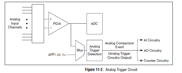
A possible workaround is that you can trigger off channels of analog inputs as well. Here is a screenshot of the M Series User Manual that shows the analog switch-off circuits:
There are a few caveats to trigger off AI channels (mentioned in Chapter 11 of the manual)
If you use a trigger to start, the analog channel that will be triggered off the coast of must be the first string in your scan list.
If you use an analog input as a reference or a relaxing break, it must be the only channel in the scan list.
I hope this helps!
Best regards
John
-
Problem of generation of the analog output on PCI-7342
I use for the control of servo motor with encoder Axis 1 of my PCI-7342 feedback
and trying to out of the velocity of the encoder on the analog output of the axis-2 which is currently not used.
For testing purposes, I pulled out a constant 16383 (half of 32767) to the analog output
through load DAC.flx permanently, but there is no voltage on the map of the motion.
I read
http://digital.NI.com/public.nsf/WebSearch/102BE3EEED8A8B0DC1256EDA0059EC47?OpenDocument
and configure my 2 axis to be a stepper motor. I also tried to disable axis - 2. None of them works for me.
Also, I tried to read the value of CAD using reading DAC.flx right after that load DAC.flx is called.
Correctly, the value was shown on the screen. (See the attached figure)
I'm really bad now. Please, please, please help!
Any possible solution is fully appreciated!
Ron Liou
-
Is a PCI-6120 card in a computer with linux useful for the analog output?
We have a PCI-6120, and we want to use in a computer with linux OS, to the analog inputs and analog outputs. I have downloaded the driver NOR-DAQmx Base 3.2 for linux, and in the file README.txt only analog input is mentioned for this Council. It is possible to use this card PCI-6120 in linux, with output and analog input computer?
Best regards
Hey, Gallas,.
This line in the README file simply refers to the PCI-6120 by its more popular, analog input subsystem (given that it is a simultaneous sampling device, the AI is the most commonly used subsystem). But NEITHER-DAQmx for Linux does not have the same limitations NOR-DAQmx base has. In other words, it supports the ability of analog output on the PCI-6120.
Kind regards
Sam
-
NEITHER 6052e: can I re - route the analog output of DAQ for PFI?
Hello
Does anyone know if it is possible to route analog output to one of the PFI (e.g. PFI0)? I use NEITHER 6052e and I would do the following: 1) output a signal to DAQ0; 2) then a few hundred milliseconds a signal of DAQ1; and then 3) read out a simple analog pulse on any output connector external to trigger an external device.
Thank you very much for your help!
Hello sometimes.
Could you please provide more information about your hardware configuration:
What devices are DAQ0 and DAQ1?
Are you using a PXI and PCI 6052?
When you say AO reroute to PFI do you mean you're trying to wire AO into a PFI line for release purposes or are you trying to exit and the analog signal of a PFI line?
-
Limit the audio via the acquisition of data, what is the analog output rate of the pci-6014?
Hello
I'm trying out audio buffers thanks to an acquisition of data pci-6014. Audio files normally have a sampling rate of 44.1 kHz, but I noticed that when I try to exit, at this rate, that I get an overflow error. I checked the datasheet and it shows a rate of output of 10 K samples per second, way too slow!
This device 6014 is quite expensive but are still unable to a stereo sound output signal... ? Is there a way to bypass this limit? It is not sensible to pay $1000 one another.
See you soon.
I don't think there is a way to increase the analogue of rates. The 6014 is old enough. A better card and cheaper, would be the 6221.
Maybe you are looking for
-
I don't get notifications on my Apple Watch
I don't get notifications on my Apple Watch
-
(C) always showing as the copyright sign
Why typing (C) always shows as the sign copyright when I type in the text?If I place the spaces between the brackets it shows as usual.All the other letters normally not spaced brackets are very good.
-
I can't find the menu of notification displayed on the lock screen. http://postimg.org/image/f64guul7r/
-
BlackBerry 10 Questions on app and updates BB10
I recently got a classic BlackBerry and I have a few questions. First of all, BlackBerry apps world somehow checked or scanned for malware? I'm pretty skeptical of third party software, but I would like to install a terminal emulator any. I was looki
-
How can I configure my xps8500 as my boot drive ssd
Hello I just got a xps8500 with 2 TB HD and SSD of 256 win7. Win7 is installed on the 2 TB drive and I would like to clone or re - install everything on the SSD and make my boot as well as all other programs (photoshop/lightroom) drive. Is there an e