Analog output using waveform Timing stops in brief
This is a pretty abstract to describe problem, so I'll try my best.
I give myself two entrances, a low and a high. Here are the tensions. I create a signal which will be the ramp from low to high and from high to low, forming a pyramid. The signal that I create is perfect. The dt signal.001 because I'm out there at 1000 Hz in an analog channel. I left it to an analog of the ExpressVI using "Waveform Timing" (the little box with a timer on this issue when the information of sampling). The problem is when I change the number of samples with this signal. It seems if I increase the examples of this signal (dt-keeping and frequency of output, thus increasing the LENGTH of the signal), the Express Vi that emits the singal stops and does not address the rest of the signal.
I can't rip off code to post here because it is not my property. I hope someone has an experience with this and can explain how an Express VI would cease treatment of an intermediate signal of the signal.
Thank you
I have corrected this problem.
If you are using an express VI, the FIRST time you call this VI, all timing information you pass, the VI will be remembered forever and he will never change. I had to replace by the low level screw and stop/clear the task in order to erase this memory.
Tags: NI Software
Similar Questions
-
How can I pause and resume the analog output using DAQmx?
I use a DAQ hardware to produce an analog waveform. I would like simply to break the output of the wave and then resume where it left off. I use DAQmx and LabVIEW 2011.
I've seen examples that use a digital or analog break trigger, but I would take a break in the software only. How can I do this?
-Joe
Hi Joe!
I spent some time thinking about it and I realized that you can technically use a fundamental mission of the analog output, as you previously wrote that runs continuously. However, the generated output samples are controlled by the sample clock pulses, and can be manipulated to fit our needs "suspension."
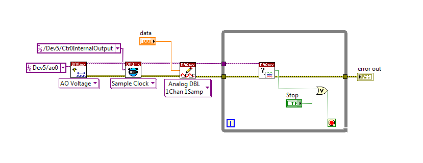
To do this, we will need another counter task that generates a pulse train (see our examples of shipping under material input and output > DAQmx > generating digital pulses > generate dig Pulse Train - Continuous.vi) that stops and starts the user to choose. This can be in another quite VI or controlled by software. We will use this as the task of our output sample clock.
Then, the task of the AO, wire a constant to the sample clock source and select ' DevX/CtrXInternalOutput"based on the counter that you specified in the task of counter. You will need to choose "I/o name of filtration" and check the box that says "include advanced terminals' and right-click of the constant. See picture attached as a reference. In this way, the task of the AO is constantly running, but it generates only actually all data when the meter running task.
Let me know if you have any questions!
Have a great day!
-
Analog output using DAQmx task
I need a signal to analog waveform using 6259 output, I followed the instructions to "Build an analogue output VI in NOR-DAQmx" in the developer area OR, when I run the code I receive thefollowing error message
"Error-50103 occurred in the DAQmx write (analog 1-d Wfm NChan NSamp) .vi:3.
Possible reasons:
The specified resource is reserved. The operation could not be performed as indicated.
Task name: _unnamedTask<1A> '
and when I press "continue" it goes ahead and track waveform on the front panel, but do not display it on the test panel in max could someone suggest how I might solve the problem?
Hello
Could you try the attached VI and let me know if it works?
I noticed that you receive information of the waveform sample clock, but the type of dynamic data that you use has no data of time in it!
-
Hello
I want to generate the continuous signal and at the same time I want to read that signal that I generate using a single card DAQ. I want to generate signal and the received signal is synchronized and in phase.
I looked at several samples on the sync, but it quiet confusing. One using the same clock of entry while the other use a trigger to start. I use the PCI-6024E DAQ card.
Can someone help me in this regard?
In two of these screenshots, the task to HAVE started first (that's what you want, because it is the task of the slave).
Typically for AO, you can simply write a unique period of your waveform, and then regenerate again and again. Your waveform would be preset before the task starts. If you need to update the waveform on the fly according to enter programming during execution of the task, you would disable the regeneration. In addition, if the wave form is such that it cannot be easily represented by a predefined buffer (for example, it is a strange frequency which is not a same ditch at the bottom of the sample clock), then non-regeneration is the way to go.
Best regards
-
Generation of two channel analog output using NI USB-6221
-
Redeclenchables/continuous to a custom waveform analog output?
Hello
I try regular output an analog signal using the box USB-6211 and Labview2009. I looked at various examples of waveform, including the retriggerableAO.vi example, but I can't seem to understand how to send a 'waveform' custom stamp (terminology is perhaps the question). In all the examples (including waveformbuffer), I ran across the single waveform, the options are sine, square, etc. Previously, I posted on this forum looking for hardware suggestions (link here) and explained what I try to do and got the big help. To sum up, I would like to read a 'waveform' from a text file, send it to the usb-6211 buffer and then continue to an analog channel. At the same time, I'll use the beginning of the analog task to trigger a digital signal once per cycle as well.
I got in what concerns the establishment of the waveform, but am stuck to figure out how to get into the buffer and setting the frequency, etc.
Thank you
Gabe
Hi Gabe,
Dennis is correct that it will take some room to modify the existing screws to fit your need. As he says, the Con Gen tension Wfm - Int Regeneration.vi Clk - no example provided with LabVIEW. In the example, it can be shown that there is a custom VI used to explain the problems that arise when a waveform of a given frequency to a frequency of sampling and outputs analog specified.
With all that said, it seems you want to read from an existing waveform file that you created and this waveform to an AO output channel. There are a few things that will be needed to know before proceeding:
-What is the waveform as you try to output (5000 samples, 10 k, 100 k, etc.)?
-What pieces of the size of the wave you want output (100 samples at a time, etc.)?
-you want to again and again, or simply run through once the waveform looping?
Assuming that you already have the waveform and will only step by step, here's what I would like:
-break the large waveform into smaller pieces of waveform of standard size
-import the waveforms in LabVIEW and create an array of waveforms
-bring the waveform in the example Dennis mentioned previously with automatic indexing enabled on the tunnel
-Remove the generator of wave functions existing the while loop
-wire your indexed table of waveform for the data of the VI DAQmx of analog output terminal
It is possible that you will have to play with the settings of your waveform and timing of your VI, but this should be a good starting point. Please let me know if something is not clear or if I have misunderstood your original message. Have a beautiful reast of the day.
Best,
-
Simulate the analog output of arbitrary waveforms
Simulate it Arbitrary Waveform VI Express can be used to generate analog signals to the physical channels in analog output mode systems such as the NI 9263? I am trying to use the VI arbitrary signal generator to produce a signal used to excite the magnetic coils.
Why don't you just try and see what happens? As far as I know, it should work.
-
Generate analog output with the software "Timing" on 6009
I see that the 6009 does not support the synchronization of the internal clock. We need to generate an analogue waveform which changes very slowly, it performs a cycle every 10-20 minutes.
I saw an old post on the use of calendar software, but can not find a way to do this using SignalExpress.
Any ideas or references to examples of messages, etc. are greatly appreciated.
Analog output clocked by the software (DAQmx) in SignalExpress
I hope this helps.
-
Using of FPGA VHDL IP and analog output
I use a system with Labview 2014 PXI. I've got Labview FPGA to program and run the card PXI-7854R.
I have the VHDL Code I want to use to control an analog output of the card. I use the IP integration node for this now but I also tried it making the process CLIP and still have not been successful. The problem that arises is that the IP integration node must be in a timed loop, while the analog output indicates that it cannot be put in a timed loop. Is there a way to provide an output of VHDL analog outputs of the card?
I tried to embed a loop timed within a while loop, but it still does not work.
I can't download the VI due to the policy of the company, but suppose I'm generating a sine wave in my VHDL code which must lead to the analog output of the card (the actual wave is company owner information but it is generated by a glance to the top of the table as a sine wave VHDL would be).
In an attempt to work the problem I retried import CLIP of the HDL code in a new project in Labview and VI. I'm still not sure about why it did not work with each other when I tried it.
For anyone who seeks to solve this problem:
I basically used this tutorial for the process CLIP: http://www.ni.com/tutorial/7444/en/
It also explains the differences between the CLAMP and the IP integration node.
-
Can what function block I use in my vi to configure a NI USB6008 of ANALOG OUTPUT.
Hello
I have a USB6008 that I use to watch the 3 entries. I would like to add the analog output AO0 to control a 0-5 volts. Which function to use in Labview 2010 for this?
The DAQ assistant let me only to acquire signals do not generate so I need something similar to the daq but Wizard to generate signals do not acquire.
Thank you
Andy
Each task can contain only 1 channel type so a task DI has all the digital input channels and a task to HAVE it cannot contain the analog input strings there is no way to mix these channels in a single task. You CAN create and run a job to HAVE and an AO task on the same device.
-
Is a PCI-6120 card in a computer with linux useful for the analog output?
We have a PCI-6120, and we want to use in a computer with linux OS, to the analog inputs and analog outputs. I have downloaded the driver NOR-DAQmx Base 3.2 for linux, and in the file README.txt only analog input is mentioned for this Council. It is possible to use this card PCI-6120 in linux, with output and analog input computer?
Best regards
Hey, Gallas,.
This line in the README file simply refers to the PCI-6120 by its more popular, analog input subsystem (given that it is a simultaneous sampling device, the AI is the most commonly used subsystem). But NEITHER-DAQmx for Linux does not have the same limitations NOR-DAQmx base has. In other words, it supports the ability of analog output on the PCI-6120.
Kind regards
Sam
-
Bipolar analog output timed sample clock Glitch on zero
With the help of a card PCI-6221, calling in the DAQmx 8.6 with a stand-alone C application DLL.
I create and fill a buffer as follows:
volts1 float64 [2048];
for (int x = 0; x)< 2048;="" x++)="">
volts1 [x] = (-0.320) + (x * (0.640 / 2048));
}
My task is created and began as follows:
TaskHandle t;
DAQmxCreateTask ("WaveTask", &t);)
DAQmxCreateAOVoltageChan (t, "PCI-6221/ao0", NULL,-5, 5, DAQmx_Val_Volts, NULL);
DAQmxCfgSampClkTiming (t, NULL, 30000, DAQmx_Val_Rising, DAQmx_Val_FiniteSamps, 2048);
DAQmxWriteAnalogF64 (t, 2048, false,-1, DAQmx_Val_GroupByScanNumber, volts1, NULL, NULL);
DAQmxStartTask (t);
DAQmxWaitUntilTaskDone (t,-1);
DAQmxStopTask (t);
DAQmxClearTask (t);
The foregoing, less creating and by disabling the task runs in an infinite loop. It generates a very good approximation of a rising wave of saw (see complete.png).
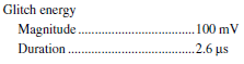
Unfortunately, when you zoom in on the time axis, a glitch becomes apparent to the point where the wave crosses zero (see glitch.png). The glitch, as shown, is about 80 mV in amplitude and 2.5 U.S. (microseconds) in duration.
It is very short, but could be the source of trouble. Is there something that can be done programmatically to fix it, or makes it look like a hardware problem?
Thank you very much!
~ Brian
If you see the Specifications for the PCI-6221, you will see that there is a specification on page 3 of the energy of glitch on the analog output of this Committee. It is a result of the CAD on the tray and is not something that can be corrected in software. The specification is:
So what you see is under the specification, so your advice is really better than the spec run.
Hope that clarifies,
-
To input analog shutdown when the analog output is completed and synchronization
Hello
I'm trying to get my LabVIEW program to send analog output to a computer and read acceleration using the cDAQ-9184. Chassis output that I use is the NI 9263 and the chassis of entry is the NI 9234. I generate a signal of white noise using LabVIEW Express signal generator.
The first problem I have is the synchronization. I had an old VI that has begun to measure the acceleration just about a second after the entry has been given to the machine. I used the LabVIEW tutorial on how to sync the analog input and output, only to discover that it does not work with two different hunts. Then I found another tutorial that shows how to synchronize different frames between them.
The second problem is the cessation of the LabVIEW program. What I want to do is to generate the signal and then simultaneously send and read the input and output analog, respectively. It is because I don't want a phase difference or any shorter signal for a direct comparison. But as soon as the signal is sent to the machine, I want the entry to stop analog playback and then then the LabVIEW program must stop. I want to be able to choose any length of signal to be generated and stop as soon as the entire duration of the signal has been sent to the machine.
I tried 'DAQmx stop', "DAQmx Timer" and 'DAQmx's task made?' and none of them have worked for me. It is also my first time on a forum posting, so I hope I gave enough information. I enclose my VI as well. The VI shows I read an entry for the analog input voltage, but I am only using this to try to get to the work programme.
I'd appreciate any help I could get.
Thanks in advance
Peter
Hi Peter,.
I have some recommendations for you that I think you will get closer to your solution. First of all, I assumed you meant that you had 1 chassis (cDAQ-9184) who had two modules in it (NOR-9263 and NOR-9234). My next steps are based on this assumption, so if it's wrong, please let me know.
For your first question about the synchronization, the code you provided is very close to what you need. You need to do, however, implement architecture master/slave for startup tasks DAQmx functions. To do this, you can add another frame to the flat sequence structure and put the master start task (input voltage) after the start slave (output voltage) task.
To manage your second question and that the program ends at the point where you, the first step is to get rid of all the logic that you use with the local variable of length of time. Rather than use this logic, just wire the node "task performed?" of "is task performed?" operate to stop the loop. This will cause your loop to stop as soon as the signal is sent to the machine.
I have some other recommendations for you that will increase the performance of your program:
(1) rather than writing on file inside the last loop, you can use the DAQmx Configure Logging (PDM) .vi. You will place this VI between DAQmx Timing.vi and DAQmx Start Task.vi to the task of the analog input voltage.
(2) after the last while loop, you want to stop the task and analog outputs as well with another DAQmx stop Task.vi.
(3) rather than using a local variable for the entrance of displacement and wiring it in the DAQmx Write.vi, you can wire directly from the output waveform of the wave to build function node.
That should help you get started in the synchronization of these tasks.
-Alex C.
Technical sales engineer
National Instruments
-
How to write constantly to analog output and read from analog inputs
Hi all -
I had a question about writing continuously to analog output reading simultaneously an analog input.
It's my first time to post a message to the community, so please let me know if I made mistakes.
I use Labview 2011 with a NEITHER-DAQ USB 6215.
I'm looking to generate a waveform and write it continuously in an analog output. It is then connected to an entry on the acquisition of data, where I am trying to sample the analog signal. (I realize, there is a system of trivial, but I'm hoping to build on it once I have run).
The task of reading from the analog input works fine, as I tested it in several other cases. I have a problem writing to the analog output.
For this task, I tried to follow the "Gen Cont Wfm Clck Int' VI to generate the wave form and start the task. I then try to write to the output of the analog timed loop. However, it does not seem to transmit a signal and doesn't give me any errors.
I have attached the VI but also a screenshot.
Please let me know if anyone has any ideas. I would really appreciate the help!
Thank you
Peter Borgstrom
We will review your tasks one at a time. First of all, the task of generation/Analog output Waveform. Generate you a waveform (I'm unsure of your VI if it is a fixed waveform or not) and send it to a defined output function to produce a waveform continuously, using N-channel and samples of N (where you set not these previously). You should not put this inside has timed loop, as the DAQ hardware has its own clock - if you simply put it in a while loop (with a stop to break out of the loop), the loop will call the function for the first points of N, wait until all N have been taken out, then call it again to another N points (up to what you press Stop).
Now, suppose that you have the output connected to a load voltage (say a decent resistance). You can wire the input terminals of your A/D converter through the same load and set up a similar analog input loop, running in parallel (i.e. in its own independent of the OD loop, while loop). You pourriez start together (with, say, a merged error since the initialization code line loops HAVE and AO become lines of error in "loops of sampling" described above), but you might want to delay loop (a little) the AI so that the OD has a chance to set the voltage before the bed.
I hope this helps.
BS
-
Analog outputs with different time scales
I use products AO of a card PCI-6731 for an application scan head and I have some difficulties to achieve peak performance, that I need. I am contolling the map with nidaqmx drivers in c ++
Basically, an output controls scanning in the direction Y (which is a line of scanning and is very fast) and the other in the X (increment once per scan line, so much slower). The complication is that both exits start at an external trigger, because positioning is synchronized to a separate data acquisition card.
Now, what I do is:
-write the scanline for 0 output waveform
-set output 1 to a given position
-say next Trigger output card
-hangs at the end and stop tasks
What I really want to do, it is just tell him to start with on each external trigger output waveform of scanline 0 and output 1 increment to the next position. So I could do a complete 2D scanner with a minimum of control software.
Any ideas on how I could best achieve this? My understanding of the nidaqmx drivers I don't see an elegant way to do it.
I could potentially do some operations on the done callback, although it makes me a little nervous because the control PC running windows, it is not a real-time operating system.
Hmm I do not know exactly but there are a couple of things (it is close)...
The output frequency of meter in your example 5 MHz (20 MHz, 2 high ticks, weak 2 ticks), which is faster than holders 6731 for a sample clock. I thought that this would have given a material error... are you looking for errors once the task runs (for example using DAQmxIsTaskDone)?. There is a DAQmxCreateCOPulseChanFreq if you want to set the clock frequency directly (it will use the appropriate default internal time base).
The task of counter generates 1000 pulses per trigger, is what determines the number of samples generated by the trigger (I assume that you want it to be 1024 aka "numSamples").
The analog output task must either use:
(1) calendar continuous if the output will repeat indefinitely as several triggers are acquired.
(2) finishes pitch (N * numSamples) samples where N is the number of lines that you want to exit and numSamples is the number of samples per line. In this case, the task will end once the lines were triggered.
Best regards
Maybe you are looking for
-
Hello I need to export a keynote presentation in quicktime that can be presented with clicks instead of itself as a video. I remember in keynote 09. I see now when I export the self cheek option already clicked in the export options window and nothin
-
Re: Satellite Pro 6000 initialize question
I have an old SP6000 which, for technical reasons, I had to format the hard drive.Since in so doing, the PC does not start upward, CD or diskettes. The message I get is - + "PXE - E61 Media test check failure cable, PXE - M0F: exit Intel. + I accesed
-
HP Compaq 8000 Elite power supply upgarde
I have a HP Compaq 8000 Elite 2010 and you must update the power to launch my new Radeon HD 6850 graphics card. After much research I found that this particular computer motherboard does not have a normal diet of 20 or 24 pins but use instead of 2 se
-
Useless help att, Motorola can help?
I had a phone unlock code for ATT, but now, it asks for a network unlock pin code SIM now, and it is likely, I should have entered the same code, but I didn't write it. ATT said it rises also unlock, but they have no code listed for give me. The best
-
This for different printers p h- When turned on my powershot hp 6380 - 3 in 1 - it turns off. This started abought a month ago and worsened as to the foregoing. Thank you taper21