Analog triggering PXI-4472
Hello everyone,
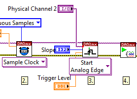
I am currently having a grip on analog option trigger PXI 4472 Council. I found on this forum a few years ago an engineer designs OR the vi ' "(attached here) Acq Cont & chart voltage-Int Start of Clk-analog as a good starting point to become familiar with the option of analog trigger for this Council.". " The VI seems to be starightworward for my level of knowledge on Labview base, but apparently I'm missing something.
Here's my problem, as far as I understand in the manual, I can use a 8 ports on 4472 as input for analog signal that can function as a trigger. In the code, edge DAQmx start analog. VI requires the source of the "APFI0" command and the help file, it should be a virtual channel through which signal will. I created the virtual channel named "APFI0" and ai0 connected to it, but I get the error message:
{Error-200265 occurred at DAQmx start Task.vi:1 Possible reason (s):}
Attempted to use an invalid trigger analog source.
Make sure you specify the command source is the name of the virtual
channel of the job or is the name of a terminal that is not readable which
the appliance can use as a source of analog control.
Property: Start.AnlgEdge.Src
{Value: APFI0}
I'm guessing that I'm not quite following how the dedicated line for the trigger is initialized. On the fron VI Panel, it is mentioned that the APFI0 is called a standard pin for M-type unit, that I (6221 PXI with BNC-2110 block), but I don't intend to use it as an analog input.
Can someone suggest how to approach this problem correctly?
Thank you in advance,
Oleks
Hello Oleks,
Maybe this will help. On the block diagram, make another copy of the list of physical channels and connect to the trigger on the DAQmx Trigger.vi Source input. There will be a red dot of coercion, but it will ensure that you get the right format for your relaxation.
What is the way analog, you choose to use a trigger, make sure it is included in the task, as below:
Tags: NI Hardware
Similar Questions
-
Why the acquired data are not from min to max (DAQmxCreateAIVoltageChan, PXI-4472) values
Hello
I'm developing a program for the PXI-4472 acquisition on opensuse 11.4 device (linux 2.6.34).
I try to acquire analog data and to read in a wav file.
Configure the task of acquisition with the following functions:
DAQmxCreateAIVoltageChan(taskHandle,"Dev1/ai0","OnboardClock",DAQmx_Val_Cfg_Default,-10.0f,10.0f,DAQmx_Val_Volts,NULL);
DAQmxCfgSampClkTiming(taskHandle,"",48000,DAQmx_Val_Rising,DAQmx_Val_FiniteSamps,48000);DAQmxDisableStartTrig (taskHandle);
I don't understand why the data stored in the wav file are not-10V,-10V but-5V, 5V... (the value of the gain is 0dB). (Perhaps a scale of 0.5?...)
Thanks for your help,
Amandine
You're right, in my example, I considered as unsigned data.
Concerning
-
Configuration of the individual channels on the PXI-4472 b
Hi, I use the card PXI-4472 b to acquire data of vibration using sensors with different frequency ranges. The problem I have is that some of the transducers require being fed by the jury (via IEPE) and some don't and I can't find a way to turn the excitement on and off for individual channels, only each other.
I am using LabVIEW 8.6 and that you have configured all channels using the nodes property to activate the excitement and specify the current, but not all channels require that.
It says clearly in the data sheet of the map of 4472 channels are individually configurable for the IEPE, can someone please tell me how to proceed?
Thanks in advance,
Darren.
Howdy Darren,
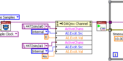
Please see the following screenshot that illustrates how to set different values for different channels of IEPE all in a single task using DAQmx. The key point here is the property of ActiveChans. Otherwise, as you know, 3GEF55NQ knowledge base: How can I activate IEPE excitement on my DSA in DAQmx device? would do the trick.
I hope this helps!
-
management communication 8184 pxi and pxi 4472
I'm trying to make an acquisition of acceleration using a pxi 4472 and UN RT pxi-8184.
Is what we me enlighten on what do I do
On MAX, I can't get the results!
Thank you
-
Error 50103 - simultaneous analog Vout and wine with start of analog triggering
Hello
I'm stuck error 50103. I looked on the Web site of NOR and worked through the 7 cases and think that my problem is the 6 case - although I'm not sure - and have no idea how to fix this. Basically, what I would do is out my signal and have receive side save after it passes through a noisy channel. To start, I have attached a trigger control so that the transmission or recording start before the input trigger exceeds a certain value (in my case, 3V).
Could someone please look at my code (attached, called 'Optical_DPPM_V3.vi')) and try to give me an indication as to what I'm doing wrong? Thank you!
Furthermore, I use examples of OR that I have also included in the .zip for reference file.
SP
P.S. hardware: LabView 8.2, NI PCI-6070E
Hi gt3000,.
Thanks for your reply. I actually solved the problem I called one of your offices directly and spoke with someone last night.
Indeed, the problem was "case 6" as it is stated on the page you gave. "." When I spole with one of your colleagues, I was directed to an example that does most of what I wanted. If anyone is interested, you can follow this path to find:
Help--> find examples--> material input and output--> DAQmx--> synchronization--> multifunction--> multi-function Synch AI - AO.vi
It seems that the trick is to use an internal digital triggering to synchronize the CLK for VI and VO.
If people are interested, I can send my final code around for a differential pulse modulator, triggered by an external analog voltage which the receiver registers and stores the values in a worksheet. My next goal is actually write the code for the receiver to demodulate information... here go us!
Thanks again,
SP
-
Routing of analog triggers seizure through RTSI in MATLAB software
Hello
I want to trigger a framegrabber PCI-1424, when a certain threshold is reached to the analog input of my PCI-6259 DAQ card channel by using the corresponding toolboxes in MATLAB. Is it possible to get a software trigger located in the analog of the DAQ by RTSI card input, so that the framegrabber is triggered through the impetus of the RTSI? Unfortunately, when you use the following code.
% Create analog input, set software trigger and RTSI lineai=analoginput('nidaq','Dev1');
ch=addchannel(ai,0);
set(ai,'TriggerType','Software')
set(ai,'TriggerCondition','Rising')
set(ai,'TriggerconditionValue',1)
set(ai,'ExternalTriggerDriveLine','RTSI0')

% Create video object and set trigger to RTSI linevid=videoinput('ni', 'img0');
triggerconfig(vid, 'hardware', 'risingEdge', 'rtsi0')
the pulse of the RTSI is sent, when the analog input object is started with
start(ai)
, but the trigger for the software has no effect on the line of the RTSI. Help or workaround would be much apreciated.
See you soon,.
Hanno
I solved the problem via using hardware triggers:
...set(ai,'TriggerType', 'HWAnalogChannel')
set(ai,'TriggerCondition', 'AboveHighValue')...
Yet, software triggers do not seem to be transmitted by the RTSI bus.
See you soon,.
Hanno
-
I have a USB-6259. I have a digital triggering (3.3V high, long 10 US, external source) that I use to control a multichannel acquisition with 9 analog inputs on the USB-6259. This trigger, I want to taste only measure of each channel as soon as possible (IE, between 1-10 USD). Digital triggers will usually come at a rate of 1 to 10 kHz, but the exact chronology may not be known. Is the 6259 capable of this? It seems the trigger configuration takes some time automatically resets for next relaxation and as a result, it lacks certain triggers.
I put the samples per second = 100000, and the number of samples = 2 (can't do 1). I use a digital release of PFI0 and triggereing on the front.
Hi TroyF,
Looks like your trigger signal can be used as a sample clock. There is an example in the Finder of the example that does what you want to do. "In LabVIEW to help' find examples... "" "" Then select material input and output "DAQmx" analog measures "voltage' Acq Cont & chart voltage-Ext Clk.vi. This allows you to select an external source as the sample clock. You put the trigger signal to a PFI line and that the source of the clock.
-
How do I synchronize pxi-6341 analog output to the analog in pxi-4304
I have an SMU-1082 chassis that contains a high-6341 and a PXI-4304 module. I went out a sinusoidal signal of pxi-6341. AO.0 channel for the pxi-4304. Channel ai.0. The pxi-4304 isn't receiving all signals up to about 75 MS later. How can I synchronize synchronization between the 2 modules together to stop this loss of data?
(Finally, I run a waveform digital off the 6341 and in a device while the 4304 captures analog response from the device. "So I'll need to have all sync'd up).
Thank you for your help,
Ron
After trying many "tricks" with various DAQmx screws, I finally found the solution. I simply had to stagger the 'task to start DAQmx' between the entry and exit, as shown in the attached photo.
Hope this helps someone.
-
Capture a sample only after analog triggering on a PXI4461 in Labview SignalExpress
-Repost on LabView forum where this thread belongs.
Hello
I capture two waveforms (external excitations) with my PXI446, one on each HAVE. I use one of them as an analog trigger (rising edge @ some tension), let's say AI0. I need the value of AI1 on time (or a fixed number of dt later) when the trigger occurs. I need just a sample.
(I almost use the 4461 as sample & hold circuit with AI1 as an input signal and the AI0 as the sign of "sample".)
Currently, I use a "subset and resample" step with a very small dt and it seems that it works, but I don't like.
The above procedure is in a conditional loop that collects 100 of these samples (acquire signals triggers 100 times) and produces a statistic of this set (using the step statistics).
Is there a better way to do it?
Thank you
Aleksandar Andreski
Hi Peter,.
Thanks for your reply.
I also think the same: do better in LV, rather than SE - LV. I tried the "subset and resample" function before, but as you say, that it cannot be made to select only a single sample. Moreover, the overhead IS are more bigger than in LV and so it slows down other parts of the measure that I have (e.g. a conditional loop).
I'll probably do a task of LV.
BTW, if I use LabView Realtime, can he run said fastest loops?
Greetings,
Aleksandar -
Analog triggering on PCIe-6251 using BNC-2120 on Mac Pro?
Hello all-
There, does anyone know how an analog trigger using a PCIe-6251 card connected to a box of BNC-2120 interface? I am running LabVIEW 8.6 on a Mac Pro OS 10.5.6 and my VI of analog data acquisition seems to work but hangs up waiting for a trigger. The trigger analog signal must be applied to the terminal APFI0 and the BNC-2120 contains no connector with this name. On the M-series cards, APFI0 corresponds to pin 20 on the map itself, but I was not to locate any information that shows how the pins of the connector BNC-2120 connect internally to different spring on its façade and BNC connectors. Sales people NOR recommended the BNC-2120 as the correct one to use with the PCIe-6251, interface box so I think that probably one of the many connectors on the front panel of the box is wired to pin 20. Am I wrong? I spent hours to connect signals to the box in the hope of getting a trigger, and nothing has worked yet. To make matters worse, reviewing the VI to trigger a data acquisition using a TTL signal connected to all of the PFI 0... 9 connectors on the BNC-2120 just causes of VI to give undefined error message ' specific 89136 route cannot be met because the hardware does not support it.» The specifications for the PCIe-6251 indicate that a digital trigger should be possible through the PFI connectors, so it's a puzzle. I have an interface BNC-2110 box in the case which turns out be a solution, nothing about it is named APFI0 either. Any suggestion would be of interest. Thank you.
-Ken1
Hi Ken,
Unfortunately, the BNC-2120 doesn't have a connection available on the APFI your M series line. The BNC-2110 has this connection available.
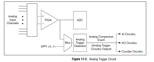
A possible workaround is that you can trigger off channels of analog inputs as well. Here is a screenshot of the M Series User Manual that shows the analog switch-off circuits:
There are a few caveats to trigger off AI channels (mentioned in Chapter 11 of the manual)
If you use a trigger to start, the analog channel that will be triggered off the coast of must be the first string in your scan list.
If you use an analog input as a reference or a relaxing break, it must be the only channel in the scan list.
I hope this helps!
Best regards
John
-
analog triggering on BNC2120 / PXI3-6361
Hello
I'm trying to run a similar trigger (falling edge) on a BNC2120 escape connected to a module PXI3-6361 (device X-series). What I read in the Installation guide for 2120 (pg 8), I should be able to use PFI 0/P1.0 (which I think is the BNC connector on the corner of high right out of the box) with DAQmx start analog Edge. Curiously, Labview does not provide a drop-down menu to select an appropriate trigger source, then for this option, I typed in the trigger source "PXI1Slot2/port0/line1. When I do that, I get an error:
Error-200265 occurred at DAQmx start Task.vi:3
Possible reasons:
Attempted to use an invalid trigger analog source.
Ensure that the source of command, you specify is the name of the virtual channel in the task or is the name of a non readable terminal that the device can use as a source of analog control.
Property: Start.AnlgEdge.Src
The corresponding value: port1/PXI1Slot2/$line0
Valid choices: V1, APFI0
Task name: _unnamedTask<6A>So I then tried "APFI0" as the source of order and received this error timeout:
Error-200284 occurred at Acq & graph tension-Int Start of Clk - analog w Hyst.vi
Some or all of the requested samples are not yet acquired.
To wait for samples become available longer read timeout or read further in your program. To make samples available more quickly, increase the frequency of sampling. If your task uses a trigger to start, make sure that your startup trigger is configured correctly. It is also possible that you have configured the external sync task, and no clock has been provided. If this is the case, provide an external clock.
Property: RelativeTo
The requested value: current playback Position
Property: Offset
Required value: 0
Device: PXI1Slot2
Task name: _unnamedTask<69>Can anyone offer some advice on how to achieve a trigger of analog voltage with this combination of features?
Thank you
Claire.
-
Configuration of the analog triggers on NI9234
I am writing a custom software that interacts with a NI 9234 scanning module, using the NiDAQmx C library. I tried to configure unity with a trigger of analog edge on one of the channels.
I use DAQmxCfgAnlgEdgeStartTrig() to configure the trigger, and it returned without error. However, when I try to call DAQmxStartTask(), it returns with the error "attempted to use an invalid trigger analog source. Ensure that the source of command, you specify is the name of the virtual channel in the task or is the name of a non readable terminal that the device can use as a source of analog trigger. »
I have set up the channel by using DAQmxCreateAIVoltageChan(). I tried the two nameToAssignToChannel of parameter null to use hardware channel name and assigning the channel a different virtual name. These two seem to work, as after the channel configuration that I can use DAQmxGetNthTaskChannel to see that the names have been configured correctly, but try to configure the trigger still does not work with the above error.
I would appreciate any idea on this issue.
Most of the Modules with 24-bit ADCs, have no trigger analog equipment. You will need to implement an algorithm to trigger in the software (target RT, FPGA host)
-
PXI-7831R configuration as analog inputs
Hello
I'm new on NI PXI, thought that I've worked on Labview. My PXI chassis has two modules analog output (PXI-6713 and 6733), a PXI-2501 FET multiplexer, a PXI-4070 DMM, PXI - 8464, an IEEE host module adaptation and the module a PXI-7831R reconfigurable i/o () .
I was able to properly configure my components using MAX.
The problem that I do exactly face 'takes analog input' using my PXI chassis.
With the modules above, I suppose that I can use the 7831R as analog I/o module.
But the problem is the 7831R is a FPGA module and it is not displayed in DAQmx.
So, where can I exactly find the analog 7831R pin (in the labview GUI) and how to use them in my block VI?
The next version of labview provides an interface to data acquisition even for 7831R? (my version of labview is 8.2.1).
Kindly help me to solve my problem.
You need the- module FPGA.
-
Analog trigger with time information
I use PXi-6133 can capture analog signals (8 differential channels) at the rate of 2 MECH. / s. I am able to capture the data and the log in the file using the logarithmic function PDM. However, processing of data takes too long as all the data are about 300 MB (for 2 cards / 16 channels, 10 seconds of vesting period).
Order to reduce the amount of data, I think the sample just the data when it is in a voltage range I can specify (for example, sample channel 1 when the signal is less than 1V), sample 2 channel when the signal is less than 1V, etc.). I am able to implement analog triggering, but he didn't tell me when the event occurs (for example, there may be multiple triggers and I need to know when the trigger happens for example to 1.0001 s, s 2.1222 etc.).
Anyone could shed some light on this?
Thank you.
KT
Well, no worries, I hope that all goes well.
-
How to export via the trigger star pxi to several dvices
Hello
I have huge problems to do this work and free time to try rarely. Joined my unfinished VI (SyncTrig - Test.vi) who needs to synchronize 9 x PXI-4472 & 1 x PXI-6713 on PXI-1006 chassis (made up of bus 3 x 6 slots). Master ST in the #2 Groove is DSA (PXI-4472), the rest 8 x DSA are inserted in slot #3-#10, and MIO (PXI-6713) is in slot #11. I need MIO to generate signals of x AO 2 (ao0:1 or ao6:7) of arbitrary length. DSAS acquire 72 x channels HAVE simultaneously until the last pair of samples AO is triggered (AO and I work at the same pace).
I understand there are 2 ways to cynchronize a all these devices - to use reference clock 10 MHz from backplane, or Star trigger bus. Trigger the beginning of ST control is supposed to start all 10 devices. I couldn't do the 'references', examples and I managed to do the "StarTrigger" example works with 2 devices so I decided to stay with the latter. Of course, I hardly expect export usable for the PXI-6713 SampleClock and we hope to get help on this forum.
Here are my 3 questions/dilemmas:
1 grouping DSAS more in a single task & export clock via ST each
I've separated the master of ST in the UpperTask export SampleClockTimebase via the bus ST and StartTrigger through the spine. The rest of the DSA are grouped in a single MiddleTask since NEITHER-DAQmx makes it easier for this type of devices PXI. In VI, UpperTask exports in a single PXI location.
Is it possible to format the string to export the clock via ST to the multiple (all the) SHAS so they can all receive it grouped together in the unique MiddleTask? Or should I use a loop for export the time base clock 8 times and feed it 8 times for all slots #3-10?
Please be specific.
2 synchronization MIO with DSA master ST via bus from ST
How can I use the TimingNode to implement SampleClockTimebase division, so that the PXI-6713 can use it in the #11 slot (LowerTask)? If this is not possible via the ST bus, can someone please show me what TimingNode (s) to use to export usable St master clock and get to MIO to synchronize the HAVE and AO closely?
3 triggers of PXI chassis
I left 2-7 as 'Dynamics' triggers to be available for NOR-DAQmx. Is it enough for the configuration shown above, from PXI devices occupy 2 of 3 independent buses in PXI-1006?
BTW, I tried a different approach (SyncTrig - No. AO.vi), but the mistake of resting LowerTask just after his TimingNode power.
Ladies and gentlemen, I hope power affirmative responses because the documentation is completely absent on synchronization PXI DAQmx and are completely dependent on WEB resources.
Thank you in advance,
Maybe you are looking for
-
Please delete my Skype account!
-
Incorrect key for Microsoft One Note
In my Satellite M40 is supposed to be a Note of Microsoft Office... When I write the product key, the program tells me it is incorrect; but is the original product key given me Toshiba... What can I do?
-
When I got to my cpu, I could use the built in mouse pad to scroll through the pages. Now, there is no move the pointer. Yes, I switch between an external mouse, and the processor built in touchpad.Help, please! It's something so simple, I know, but
-
Walkman app (version: 8.4.A.5.4) stopped working suddenly. After tapping on the application, I get a message "Unfortunately, Walkman has stopped." and if the application cannot be opened even, no music can be read even through the widget of app Walkm
-
Error 1303 when trying to install Blackberry Desktop Software
I tried to install the latest version of Blackberry Desktop software (5.0.1) and I can't do it. I get "Error 1303. The installer has sufficient privileges to access this directory: C:\Program Research In Motion\Blackberry\1003. The installation canno