Routing of analog triggers seizure through RTSI in MATLAB software
Hello
I want to trigger a framegrabber PCI-1424, when a certain threshold is reached to the analog input of my PCI-6259 DAQ card channel by using the corresponding toolboxes in MATLAB. Is it possible to get a software trigger located in the analog of the DAQ by RTSI card input, so that the framegrabber is triggered through the impetus of the RTSI? Unfortunately, when you use the following code.
% Create analog input, set software trigger and RTSI lineai=analoginput('nidaq','Dev1');
ch=addchannel(ai,0);
set(ai,'TriggerType','Software')
set(ai,'TriggerCondition','Rising')
set(ai,'TriggerconditionValue',1)
set(ai,'ExternalTriggerDriveLine','RTSI0')

% Create video object and set trigger to RTSI linevid=videoinput('ni', 'img0');
triggerconfig(vid, 'hardware', 'risingEdge', 'rtsi0')
the pulse of the RTSI is sent, when the analog input object is started with
start(ai)
, but the trigger for the software has no effect on the line of the RTSI. Help or workaround would be much apreciated.
See you soon,.
Hanno
I solved the problem via using hardware triggers:
...set(ai,'TriggerType', 'HWAnalogChannel')
set(ai,'TriggerCondition', 'AboveHighValue')...
Yet, software triggers do not seem to be transmitted by the RTSI bus.
See you soon,.
Hanno
Tags: NI Hardware
Similar Questions
-
Analog triggering on PCIe-6251 using BNC-2120 on Mac Pro?
Hello all-
There, does anyone know how an analog trigger using a PCIe-6251 card connected to a box of BNC-2120 interface? I am running LabVIEW 8.6 on a Mac Pro OS 10.5.6 and my VI of analog data acquisition seems to work but hangs up waiting for a trigger. The trigger analog signal must be applied to the terminal APFI0 and the BNC-2120 contains no connector with this name. On the M-series cards, APFI0 corresponds to pin 20 on the map itself, but I was not to locate any information that shows how the pins of the connector BNC-2120 connect internally to different spring on its façade and BNC connectors. Sales people NOR recommended the BNC-2120 as the correct one to use with the PCIe-6251, interface box so I think that probably one of the many connectors on the front panel of the box is wired to pin 20. Am I wrong? I spent hours to connect signals to the box in the hope of getting a trigger, and nothing has worked yet. To make matters worse, reviewing the VI to trigger a data acquisition using a TTL signal connected to all of the PFI 0... 9 connectors on the BNC-2120 just causes of VI to give undefined error message ' specific 89136 route cannot be met because the hardware does not support it.» The specifications for the PCIe-6251 indicate that a digital trigger should be possible through the PFI connectors, so it's a puzzle. I have an interface BNC-2110 box in the case which turns out be a solution, nothing about it is named APFI0 either. Any suggestion would be of interest. Thank you.
-Ken1
Hi Ken,
Unfortunately, the BNC-2120 doesn't have a connection available on the APFI your M series line. The BNC-2110 has this connection available.
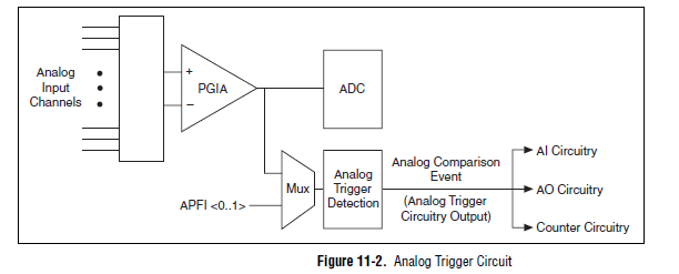
A possible workaround is that you can trigger off channels of analog inputs as well. Here is a screenshot of the M Series User Manual that shows the analog switch-off circuits:
There are a few caveats to trigger off AI channels (mentioned in Chapter 11 of the manual)
If you use a trigger to start, the analog channel that will be triggered off the coast of must be the first string in your scan list.
If you use an analog input as a reference or a relaxing break, it must be the only channel in the scan list.
I hope this helps!
Best regards
John
-
Error 50103 - simultaneous analog Vout and wine with start of analog triggering
Hello
I'm stuck error 50103. I looked on the Web site of NOR and worked through the 7 cases and think that my problem is the 6 case - although I'm not sure - and have no idea how to fix this. Basically, what I would do is out my signal and have receive side save after it passes through a noisy channel. To start, I have attached a trigger control so that the transmission or recording start before the input trigger exceeds a certain value (in my case, 3V).
Could someone please look at my code (attached, called 'Optical_DPPM_V3.vi')) and try to give me an indication as to what I'm doing wrong? Thank you!
Furthermore, I use examples of OR that I have also included in the .zip for reference file.
SP
P.S. hardware: LabView 8.2, NI PCI-6070E
Hi gt3000,.
Thanks for your reply. I actually solved the problem I called one of your offices directly and spoke with someone last night.
Indeed, the problem was "case 6" as it is stated on the page you gave. "." When I spole with one of your colleagues, I was directed to an example that does most of what I wanted. If anyone is interested, you can follow this path to find:
Help--> find examples--> material input and output--> DAQmx--> synchronization--> multifunction--> multi-function Synch AI - AO.vi
It seems that the trick is to use an internal digital triggering to synchronize the CLK for VI and VO.
If people are interested, I can send my final code around for a differential pulse modulator, triggered by an external analog voltage which the receiver registers and stores the values in a worksheet. My next goal is actually write the code for the receiver to demodulate information... here go us!
Thanks again,
SP
-
I have a USB-6259. I have a digital triggering (3.3V high, long 10 US, external source) that I use to control a multichannel acquisition with 9 analog inputs on the USB-6259. This trigger, I want to taste only measure of each channel as soon as possible (IE, between 1-10 USD). Digital triggers will usually come at a rate of 1 to 10 kHz, but the exact chronology may not be known. Is the 6259 capable of this? It seems the trigger configuration takes some time automatically resets for next relaxation and as a result, it lacks certain triggers.
I put the samples per second = 100000, and the number of samples = 2 (can't do 1). I use a digital release of PFI0 and triggereing on the front.
Hi TroyF,
Looks like your trigger signal can be used as a sample clock. There is an example in the Finder of the example that does what you want to do. "In LabVIEW to help' find examples... "" "" Then select material input and output "DAQmx" analog measures "voltage' Acq Cont & chart voltage-Ext Clk.vi. This allows you to select an external source as the sample clock. You put the trigger signal to a PFI line and that the source of the clock.
-
Capture a sample only after analog triggering on a PXI4461 in Labview SignalExpress
-Repost on LabView forum where this thread belongs.
Hello
I capture two waveforms (external excitations) with my PXI446, one on each HAVE. I use one of them as an analog trigger (rising edge @ some tension), let's say AI0. I need the value of AI1 on time (or a fixed number of dt later) when the trigger occurs. I need just a sample.
(I almost use the 4461 as sample & hold circuit with AI1 as an input signal and the AI0 as the sign of "sample".)
Currently, I use a "subset and resample" step with a very small dt and it seems that it works, but I don't like.
The above procedure is in a conditional loop that collects 100 of these samples (acquire signals triggers 100 times) and produces a statistic of this set (using the step statistics).
Is there a better way to do it?
Thank you
Aleksandar Andreski
Hi Peter,.
Thanks for your reply.
I also think the same: do better in LV, rather than SE - LV. I tried the "subset and resample" function before, but as you say, that it cannot be made to select only a single sample. Moreover, the overhead IS are more bigger than in LV and so it slows down other parts of the measure that I have (e.g. a conditional loop).
I'll probably do a task of LV.
BTW, if I use LabView Realtime, can he run said fastest loops?
Greetings,
Aleksandar -
NEITHER 6052e: can I re - route the analog output of DAQ for PFI?
Hello
Does anyone know if it is possible to route analog output to one of the PFI (e.g. PFI0)? I use NEITHER 6052e and I would do the following: 1) output a signal to DAQ0; 2) then a few hundred milliseconds a signal of DAQ1; and then 3) read out a simple analog pulse on any output connector external to trigger an external device.
Thank you very much for your help!
Hello sometimes.
Could you please provide more information about your hardware configuration:
What devices are DAQ0 and DAQ1?
Are you using a PXI and PCI 6052?
When you say AO reroute to PFI do you mean you're trying to wire AO into a PFI line for release purposes or are you trying to exit and the analog signal of a PFI line?
-
Hello everyone,
I am currently having a grip on analog option trigger PXI 4472 Council. I found on this forum a few years ago an engineer designs OR the vi ' "(attached here) Acq Cont & chart voltage-Int Start of Clk-analog as a good starting point to become familiar with the option of analog trigger for this Council.". " The VI seems to be starightworward for my level of knowledge on Labview base, but apparently I'm missing something.
Here's my problem, as far as I understand in the manual, I can use a 8 ports on 4472 as input for analog signal that can function as a trigger. In the code, edge DAQmx start analog. VI requires the source of the "APFI0" command and the help file, it should be a virtual channel through which signal will. I created the virtual channel named "APFI0" and ai0 connected to it, but I get the error message:
{Error-200265 occurred at DAQmx start Task.vi:1 Possible reason (s):}
Attempted to use an invalid trigger analog source.
Make sure you specify the command source is the name of the virtual
channel of the job or is the name of a terminal that is not readable which
the appliance can use as a source of analog control.
Property: Start.AnlgEdge.Src
{Value: APFI0}I'm guessing that I'm not quite following how the dedicated line for the trigger is initialized. On the fron VI Panel, it is mentioned that the APFI0 is called a standard pin for M-type unit, that I (6221 PXI with BNC-2110 block), but I don't intend to use it as an analog input.
Can someone suggest how to approach this problem correctly?
Thank you in advance,
Oleks
Hello Oleks,
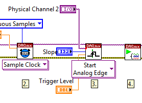
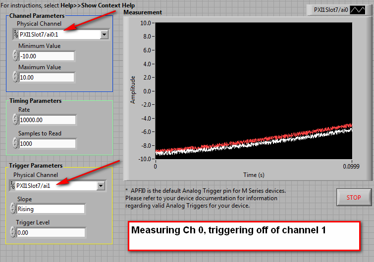
Maybe this will help. On the block diagram, make another copy of the list of physical channels and connect to the trigger on the DAQmx Trigger.vi Source input. There will be a red dot of coercion, but it will ensure that you get the right format for your relaxation.
What is the way analog, you choose to use a trigger, make sure it is included in the task, as below:
-
Configuration of the router to allow VPN traffic through
I would like to ask for assistance with a specific configuration to allow VPN traffic through a router from 1721.
The network configuration is the following:
Internet - Cisco 1721 - Cisco PIX 506th - LAN
Remote clients connect from the internet by using the Cisco VPN client. The 1721 should just pass the packets through to the PIX, which is 192.168.0.2. Inside of the interface of the router is 192.168.0.1.
The pix was originally configured with a public ip address and has been tested to work well to authenticate VPN connections and passing traffic in the local network. Then, the external ip address was changed to 192.168.0.2 and the router behind.
The 1721 is configured with an ADSL connection, with fall-over automatic for an asynchronous connection. This configuration does not work well, and in the local network, users have normal internet access. I added lists of access for udp, esp and the traffic of the ahp.
Cisco VPN clients receive an error indicating that the remote control is not responding.
I have attached the router for reference, and any help would be greatly apreciated.
Manual.
Brian
For VPN clients reach the PIX to complete their VPN the PIX needs to an address that is accessible from the outside where the customers are. When the PIX was a public address was obviously easy for guests to reach the PIX. When you give the PIX one address private, then he must make a translation. And this becomes a problem if the translation is dynamic.
You have provided a static translation that is what is needed. But you have restricted the TCP 3389. I don't know why you restricted it in this way. What is supposed to happen for ISAKMP and ESP, AHP traffic? How is it to be translated?
If there is not a static translation for ISAKMP traffic, ESP and AHP so clients don't know how to reach the server. Which brings me to the question of what the address is configured in the client to the server?
HTH
Rick
-
analog triggering on BNC2120 / PXI3-6361
Hello
I'm trying to run a similar trigger (falling edge) on a BNC2120 escape connected to a module PXI3-6361 (device X-series). What I read in the Installation guide for 2120 (pg 8), I should be able to use PFI 0/P1.0 (which I think is the BNC connector on the corner of high right out of the box) with DAQmx start analog Edge. Curiously, Labview does not provide a drop-down menu to select an appropriate trigger source, then for this option, I typed in the trigger source "PXI1Slot2/port0/line1. When I do that, I get an error:
Error-200265 occurred at DAQmx start Task.vi:3
Possible reasons:
Attempted to use an invalid trigger analog source.
Ensure that the source of command, you specify is the name of the virtual channel in the task or is the name of a non readable terminal that the device can use as a source of analog control.
Property: Start.AnlgEdge.Src
The corresponding value: port1/PXI1Slot2/$line0
Valid choices: V1, APFI0
Task name: _unnamedTask<6A>So I then tried "APFI0" as the source of order and received this error timeout:
Error-200284 occurred at Acq & graph tension-Int Start of Clk - analog w Hyst.vi
Some or all of the requested samples are not yet acquired.
To wait for samples become available longer read timeout or read further in your program. To make samples available more quickly, increase the frequency of sampling. If your task uses a trigger to start, make sure that your startup trigger is configured correctly. It is also possible that you have configured the external sync task, and no clock has been provided. If this is the case, provide an external clock.
Property: RelativeTo
The requested value: current playback Position
Property: Offset
Required value: 0
Device: PXI1Slot2
Task name: _unnamedTask<69>Can anyone offer some advice on how to achieve a trigger of analog voltage with this combination of features?
Thank you
Claire.
-
And outputs analog table 2D through 4 lines (PCI 6711)
Hello
I want to design a user interface where the user can set the level of analog voltage of a specific analog channel for a certain period of time. Basically, I need a 2D table where the columns represent each channel on the PCI 6711 map (Ao 0:3) and the lines represent a specific amount of time for each line to last. I guess it would have to be another array of verical 1 d with integers representing the number of ticks that each line will last. I can't seem to find an example of code where this is implemented, so some examples or suggestions would be grealty appreciated. I have included a picture of another program that does this, and I would like to reproduce this configuration.
Pass the array using a loop for. This example gets each line. You can then use the subset of the table to get the columns with the voltage. This gets wired to a game of writing DAQmx for n channels 1 sample. The duration column index and son to a delay. Try it and post back you're stuck.
Sorry, but the answer above is meaningless to me.
-
Configuration of the analog triggers on NI9234
I am writing a custom software that interacts with a NI 9234 scanning module, using the NiDAQmx C library. I tried to configure unity with a trigger of analog edge on one of the channels.
I use DAQmxCfgAnlgEdgeStartTrig() to configure the trigger, and it returned without error. However, when I try to call DAQmxStartTask(), it returns with the error "attempted to use an invalid trigger analog source. Ensure that the source of command, you specify is the name of the virtual channel in the task or is the name of a non readable terminal that the device can use as a source of analog trigger. »
I have set up the channel by using DAQmxCreateAIVoltageChan(). I tried the two nameToAssignToChannel of parameter null to use hardware channel name and assigning the channel a different virtual name. These two seem to work, as after the channel configuration that I can use DAQmxGetNthTaskChannel to see that the names have been configured correctly, but try to configure the trigger still does not work with the above error.
I would appreciate any idea on this issue.
Most of the Modules with 24-bit ADCs, have no trigger analog equipment. You will need to implement an algorithm to trigger in the software (target RT, FPGA host)
-
I have a laptop HP with XP pro. I have a network with 2 computers laptops (Dell and HP), 1 office and 1 DP300U DLINK print server with a static IP address. I use a LINKSYS WRT110 router. Everything is connected through this router. I can ping ALL laptops, the office and the print server. I can access internet from all laptops and office. All THE MACHINES are in the same workgroup. Only from my DESKTOP (XP HOME), I can click on FAVORITES NETWORK, click VIEW group of WORK COMPUTERS and I can see the other compters and the print server. However, since my computer Dell laptop or HP LAPTOP (XP PRO) I can PING the router and the journal in it, all the other machines and print server but can NOT SEE THE OTHER COMPUTERS or ACCESS THE PORTABLE HP computer or the other laptop. I turned off all firewalls and firewall McAfee (PORTABLE HP computer) and still no joy. I think that there is a box ticked somewhere or the one that is checked and who should not, but I can't find out where it is or something else to look at. Any ideas would be appreciated.
I suggest you take a look at:
http://support.Microsoft.com/kb/318030/
You can run fixit in the PC that encourage the problem this fixit automatically.
-
I was wondering if anyone knew a good article to explain via a VPN routing works.
If you a SSL VPN with transatlantic lines in it are the routing table
----------------------------------------------------------------------------------------
Route outside 0.0.0.0 0.0.0.0 204.90.21.1 1
Route within xxxx 255.255.255.255 172.18.0.1 1
Route inside 204.110.220.0 255.255.240.0 172.18.0.1 1
Route inside 204.110.250.0 255.255.255.0 172.18.0.1 1
The VPN works great, but I'm just wondeirng how it is possible to connect to the VPN
and then with successful ping 192.168.1.1 or 204.110.210.0 when there is no route in the route
table of the SAA.
Maybe I just don't understand how routing works by the VPN through ASA so to speak.
Well, basically once the VPN client creates a connection to the VPN server, if traffic matches to networks, pushed by the server, the traffic gets encrypted and sent to the peer it VPN using the default gateway to the client.
The VPN server or peer receives the packet unencrypts he then sends it to the printer.
The routing part works pretty all the only difference is that the package traverses encryped thruought Internet.
-
We have a problem get sustained response of our HP Officejet 7000 Wide Format Printer - E809a which is connected to the network wireless ethernet to a router Netgear cable. We tried stripping on the software driver & uninstall of the printer of the registry, and then re-setup from latest downloads from the HP site. It works, especially if the device is set as the default printer, but the printer greys out less than an hour in the device registry and the default value automatically resets to another printer. Does anyone know why this printer loses his connection?
Hi @Harry64,
I see by your post that continues to change the default printer. I'd love to help you.
Disable the SMTP setting in print, to see drivers if this will help.
Devices and printers, click with the right button on the printer and click on printer properties, click the Ports tab, select Configure the Port, clear the SMTP check box and the printer should display online.
If the problem persists, please take a look at this document. Monofunctional and HP Printers Multifunction - "the printer is offline" Message appears on the computer and the printer does not print: Windows 7
If you appreciate my efforts, please click on the "Thumbs up" button below. Thank you.
-
difference between RTSI or IFP in synchronization
Hi all
I have a small question on the difference between the PFI and RTSI pin used in synchronization. I have 6711 card and I'm going to use external clock to drive the analog output and the output of the meter. Someone said I can use PFI as a source and I have read the manual, it looks like I can use pin 20 MHz of RTSI as the temporal also. So if I plugged a clock 10 MHz on the pin of temporal RTSI, means all output is based on this clock? What do I have to configure the software to make it work? I it is confusing because RTSI has 8 pairs of poles and the first is a time base, there are some for the analog output, some for the analog input. I need of synchronizing the output meter and analog output. Should I change connect the external clock to the time base RTSI or connect to an analogue output RTSI and out of meter?
Hello there;
The main difference is that the purchased triggers or events generated from the PFI lines are synchronous with the data, so that they have a relationship of data/clock phase. On the other hand, triggers acquired with RTSI lines are not in sync with the data so that there may be no such relationship.
So pretty much if you need triggers and events to synchronize with the clock uses the PFI lines
Here is a KB with more information
It may be useful
Greetings
Maybe you are looking for
-
my default text will come out as question marks in a box
I am on OS x EL Capitan Office. My default text will come out as question marks in a box for each character?
-
For several days, while all other sites work as fine as before on Firefox, Wikipedia works very poorly: it responds very slowly and often gets stuck half-way before opening a page. I tried several solutions, but the problem is recurring. On another p
-
USB key will be always analyzed
English is not my native, so I'm sorry if I make mistakes. My Toshiba laptop (windows 7) open the USB drive too long. Whenever I plug a USB key, he asks me to analyze the stick and check if there are errors, or proceed without analyzing. The problem
-
Satellite C660 - 23 M - graphics driver update problem
New to this forum, so don't know if this has been covered. Have installed Photoshop elements 11 and Prime Minister 11.Elements of program works ok but cannot get the items first to open the new project. Adobe advises trying to update the drivers I ha
-
Start the custom of MacBook in any mode or recovery (white screen)
MacBook Pro late 2011 with El Capitan My macbook does not start in any mode. There is just the usual startup chime and after the apple logo bar progresses about 1/8, a white screen appears and stays like that. I tried leaving on the white screen unti