analog triggering rate
I have a USB-6259. I have a digital triggering (3.3V high, long 10 US, external source) that I use to control a multichannel acquisition with 9 analog inputs on the USB-6259. This trigger, I want to taste only measure of each channel as soon as possible (IE, between 1-10 USD). Digital triggers will usually come at a rate of 1 to 10 kHz, but the exact chronology may not be known. Is the 6259 capable of this? It seems the trigger configuration takes some time automatically resets for next relaxation and as a result, it lacks certain triggers.
I put the samples per second = 100000, and the number of samples = 2 (can't do 1). I use a digital release of PFI0 and triggereing on the front.
Hi TroyF,
Looks like your trigger signal can be used as a sample clock. There is an example in the Finder of the example that does what you want to do. "In LabVIEW to help' find examples... "" "" Then select material input and output "DAQmx" analog measures "voltage' Acq Cont & chart voltage-Ext Clk.vi. This allows you to select an external source as the sample clock. You put the trigger signal to a PFI line and that the source of the clock.
Tags: NI Hardware
Similar Questions
-
Error 50103 - simultaneous analog Vout and wine with start of analog triggering
Hello
I'm stuck error 50103. I looked on the Web site of NOR and worked through the 7 cases and think that my problem is the 6 case - although I'm not sure - and have no idea how to fix this. Basically, what I would do is out my signal and have receive side save after it passes through a noisy channel. To start, I have attached a trigger control so that the transmission or recording start before the input trigger exceeds a certain value (in my case, 3V).
Could someone please look at my code (attached, called 'Optical_DPPM_V3.vi')) and try to give me an indication as to what I'm doing wrong? Thank you!
Furthermore, I use examples of OR that I have also included in the .zip for reference file.
SP
P.S. hardware: LabView 8.2, NI PCI-6070E
Hi gt3000,.
Thanks for your reply. I actually solved the problem I called one of your offices directly and spoke with someone last night.
Indeed, the problem was "case 6" as it is stated on the page you gave. "." When I spole with one of your colleagues, I was directed to an example that does most of what I wanted. If anyone is interested, you can follow this path to find:
Help--> find examples--> material input and output--> DAQmx--> synchronization--> multifunction--> multi-function Synch AI - AO.vi
It seems that the trick is to use an internal digital triggering to synchronize the CLK for VI and VO.
If people are interested, I can send my final code around for a differential pulse modulator, triggered by an external analog voltage which the receiver registers and stores the values in a worksheet. My next goal is actually write the code for the receiver to demodulate information... here go us!
Thanks again,
SP
-
Routing of analog triggers seizure through RTSI in MATLAB software
Hello
I want to trigger a framegrabber PCI-1424, when a certain threshold is reached to the analog input of my PCI-6259 DAQ card channel by using the corresponding toolboxes in MATLAB. Is it possible to get a software trigger located in the analog of the DAQ by RTSI card input, so that the framegrabber is triggered through the impetus of the RTSI? Unfortunately, when you use the following code.
% Create analog input, set software trigger and RTSI lineai=analoginput('nidaq','Dev1');
ch=addchannel(ai,0);
set(ai,'TriggerType','Software')
set(ai,'TriggerCondition','Rising')
set(ai,'TriggerconditionValue',1)
set(ai,'ExternalTriggerDriveLine','RTSI0')

% Create video object and set trigger to RTSI linevid=videoinput('ni', 'img0');
triggerconfig(vid, 'hardware', 'risingEdge', 'rtsi0')
the pulse of the RTSI is sent, when the analog input object is started with
start(ai)
, but the trigger for the software has no effect on the line of the RTSI. Help or workaround would be much apreciated.
See you soon,.
Hanno
I solved the problem via using hardware triggers:
...set(ai,'TriggerType', 'HWAnalogChannel')
set(ai,'TriggerCondition', 'AboveHighValue')...
Yet, software triggers do not seem to be transmitted by the RTSI bus.
See you soon,.
Hanno
-
Capture a sample only after analog triggering on a PXI4461 in Labview SignalExpress
-Repost on LabView forum where this thread belongs.
Hello
I capture two waveforms (external excitations) with my PXI446, one on each HAVE. I use one of them as an analog trigger (rising edge @ some tension), let's say AI0. I need the value of AI1 on time (or a fixed number of dt later) when the trigger occurs. I need just a sample.
(I almost use the 4461 as sample & hold circuit with AI1 as an input signal and the AI0 as the sign of "sample".)
Currently, I use a "subset and resample" step with a very small dt and it seems that it works, but I don't like.
The above procedure is in a conditional loop that collects 100 of these samples (acquire signals triggers 100 times) and produces a statistic of this set (using the step statistics).
Is there a better way to do it?
Thank you
Aleksandar Andreski
Hi Peter,.
Thanks for your reply.
I also think the same: do better in LV, rather than SE - LV. I tried the "subset and resample" function before, but as you say, that it cannot be made to select only a single sample. Moreover, the overhead IS are more bigger than in LV and so it slows down other parts of the measure that I have (e.g. a conditional loop).
I'll probably do a task of LV.
BTW, if I use LabView Realtime, can he run said fastest loops?
Greetings,
Aleksandar -
Analog triggering on PCIe-6251 using BNC-2120 on Mac Pro?
Hello all-
There, does anyone know how an analog trigger using a PCIe-6251 card connected to a box of BNC-2120 interface? I am running LabVIEW 8.6 on a Mac Pro OS 10.5.6 and my VI of analog data acquisition seems to work but hangs up waiting for a trigger. The trigger analog signal must be applied to the terminal APFI0 and the BNC-2120 contains no connector with this name. On the M-series cards, APFI0 corresponds to pin 20 on the map itself, but I was not to locate any information that shows how the pins of the connector BNC-2120 connect internally to different spring on its façade and BNC connectors. Sales people NOR recommended the BNC-2120 as the correct one to use with the PCIe-6251, interface box so I think that probably one of the many connectors on the front panel of the box is wired to pin 20. Am I wrong? I spent hours to connect signals to the box in the hope of getting a trigger, and nothing has worked yet. To make matters worse, reviewing the VI to trigger a data acquisition using a TTL signal connected to all of the PFI 0... 9 connectors on the BNC-2120 just causes of VI to give undefined error message ' specific 89136 route cannot be met because the hardware does not support it.» The specifications for the PCIe-6251 indicate that a digital trigger should be possible through the PFI connectors, so it's a puzzle. I have an interface BNC-2110 box in the case which turns out be a solution, nothing about it is named APFI0 either. Any suggestion would be of interest. Thank you.
-Ken1
Hi Ken,
Unfortunately, the BNC-2120 doesn't have a connection available on the APFI your M series line. The BNC-2110 has this connection available.
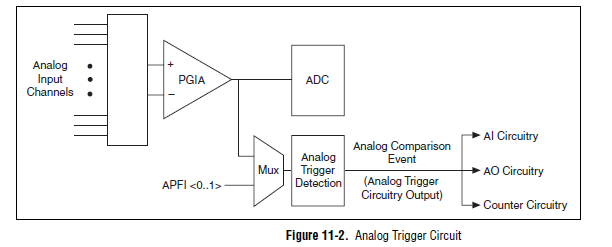
A possible workaround is that you can trigger off channels of analog inputs as well. Here is a screenshot of the M Series User Manual that shows the analog switch-off circuits:
There are a few caveats to trigger off AI channels (mentioned in Chapter 11 of the manual)
If you use a trigger to start, the analog channel that will be triggered off the coast of must be the first string in your scan list.
If you use an analog input as a reference or a relaxing break, it must be the only channel in the scan list.
I hope this helps!
Best regards
John
-
analog triggering on BNC2120 / PXI3-6361
Hello
I'm trying to run a similar trigger (falling edge) on a BNC2120 escape connected to a module PXI3-6361 (device X-series). What I read in the Installation guide for 2120 (pg 8), I should be able to use PFI 0/P1.0 (which I think is the BNC connector on the corner of high right out of the box) with DAQmx start analog Edge. Curiously, Labview does not provide a drop-down menu to select an appropriate trigger source, then for this option, I typed in the trigger source "PXI1Slot2/port0/line1. When I do that, I get an error:
Error-200265 occurred at DAQmx start Task.vi:3
Possible reasons:
Attempted to use an invalid trigger analog source.
Ensure that the source of command, you specify is the name of the virtual channel in the task or is the name of a non readable terminal that the device can use as a source of analog control.
Property: Start.AnlgEdge.Src
The corresponding value: port1/PXI1Slot2/$line0
Valid choices: V1, APFI0
Task name: _unnamedTask<6A>So I then tried "APFI0" as the source of order and received this error timeout:
Error-200284 occurred at Acq & graph tension-Int Start of Clk - analog w Hyst.vi
Some or all of the requested samples are not yet acquired.
To wait for samples become available longer read timeout or read further in your program. To make samples available more quickly, increase the frequency of sampling. If your task uses a trigger to start, make sure that your startup trigger is configured correctly. It is also possible that you have configured the external sync task, and no clock has been provided. If this is the case, provide an external clock.
Property: RelativeTo
The requested value: current playback Position
Property: Offset
Required value: 0
Device: PXI1Slot2
Task name: _unnamedTask<69>Can anyone offer some advice on how to achieve a trigger of analog voltage with this combination of features?
Thank you
Claire.
-
Configuration of the analog triggers on NI9234
I am writing a custom software that interacts with a NI 9234 scanning module, using the NiDAQmx C library. I tried to configure unity with a trigger of analog edge on one of the channels.
I use DAQmxCfgAnlgEdgeStartTrig() to configure the trigger, and it returned without error. However, when I try to call DAQmxStartTask(), it returns with the error "attempted to use an invalid trigger analog source. Ensure that the source of command, you specify is the name of the virtual channel in the task or is the name of a non readable terminal that the device can use as a source of analog trigger. »
I have set up the channel by using DAQmxCreateAIVoltageChan(). I tried the two nameToAssignToChannel of parameter null to use hardware channel name and assigning the channel a different virtual name. These two seem to work, as after the channel configuration that I can use DAQmxGetNthTaskChannel to see that the names have been configured correctly, but try to configure the trigger still does not work with the above error.
I would appreciate any idea on this issue.
Most of the Modules with 24-bit ADCs, have no trigger analog equipment. You will need to implement an algorithm to trigger in the software (target RT, FPGA host)
-
Hello everyone,
I am currently having a grip on analog option trigger PXI 4472 Council. I found on this forum a few years ago an engineer designs OR the vi ' "(attached here) Acq Cont & chart voltage-Int Start of Clk-analog as a good starting point to become familiar with the option of analog trigger for this Council.". " The VI seems to be starightworward for my level of knowledge on Labview base, but apparently I'm missing something.
Here's my problem, as far as I understand in the manual, I can use a 8 ports on 4472 as input for analog signal that can function as a trigger. In the code, edge DAQmx start analog. VI requires the source of the "APFI0" command and the help file, it should be a virtual channel through which signal will. I created the virtual channel named "APFI0" and ai0 connected to it, but I get the error message:
{Error-200265 occurred at DAQmx start Task.vi:1 Possible reason (s):}
Attempted to use an invalid trigger analog source.
Make sure you specify the command source is the name of the virtual
channel of the job or is the name of a terminal that is not readable which
the appliance can use as a source of analog control.
Property: Start.AnlgEdge.Src
{Value: APFI0}I'm guessing that I'm not quite following how the dedicated line for the trigger is initialized. On the fron VI Panel, it is mentioned that the APFI0 is called a standard pin for M-type unit, that I (6221 PXI with BNC-2110 block), but I don't intend to use it as an analog input.
Can someone suggest how to approach this problem correctly?
Thank you in advance,
Oleks
Hello Oleks,
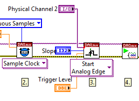
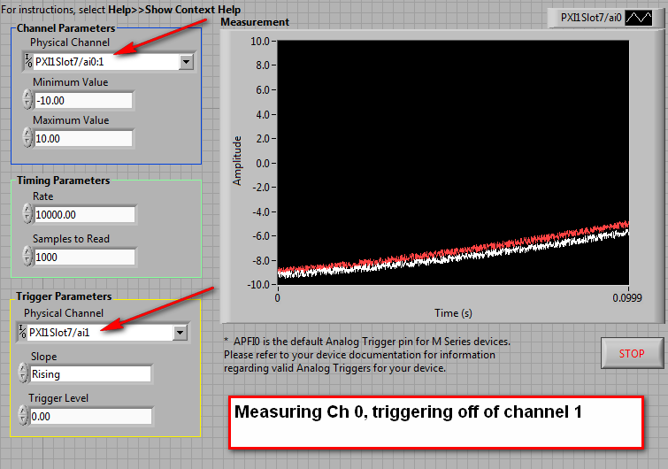
Maybe this will help. On the block diagram, make another copy of the list of physical channels and connect to the trigger on the DAQmx Trigger.vi Source input. There will be a red dot of coercion, but it will ensure that you get the right format for your relaxation.
What is the way analog, you choose to use a trigger, make sure it is included in the task, as below:
-
Limit the audio via the acquisition of data, what is the analog output rate of the pci-6014?
Hello
I'm trying out audio buffers thanks to an acquisition of data pci-6014. Audio files normally have a sampling rate of 44.1 kHz, but I noticed that when I try to exit, at this rate, that I get an overflow error. I checked the datasheet and it shows a rate of output of 10 K samples per second, way too slow!
This device 6014 is quite expensive but are still unable to a stereo sound output signal... ? Is there a way to bypass this limit? It is not sensible to pay $1000 one another.
See you soon.
I don't think there is a way to increase the analogue of rates. The 6014 is old enough. A better card and cheaper, would be the 6221.
-
Analog trigger with time information
I use PXi-6133 can capture analog signals (8 differential channels) at the rate of 2 MECH. / s. I am able to capture the data and the log in the file using the logarithmic function PDM. However, processing of data takes too long as all the data are about 300 MB (for 2 cards / 16 channels, 10 seconds of vesting period).
Order to reduce the amount of data, I think the sample just the data when it is in a voltage range I can specify (for example, sample channel 1 when the signal is less than 1V), sample 2 channel when the signal is less than 1V, etc.). I am able to implement analog triggering, but he didn't tell me when the event occurs (for example, there may be multiple triggers and I need to know when the trigger happens for example to 1.0001 s, s 2.1222 etc.).
Anyone could shed some light on this?
Thank you.
KT
Well, no worries, I hope that all goes well.
-
Hi all
I have a VI that measures analog 5 separate lines (pressure sensors, thermocouples in temperature, etc.) and 3 lines of DI/O (for a coder angular step phaseB and IndexZ). I'm having a few problems (as follows);
1 trying to simultaneously capture the reading encoder and analog playback, I tried setting them up on the same basis of 100 kHz time although the encoder reads at a different rate from that of the lines of I which produces squewed data. So I tried to make the lines to HAVE it read at each rising edge of the pulse of the encoder, (this had to number 2). Is there a way to make the lines SO the DI/O on the same clock sampling or better still in the same job for DAQmx?
2. analog digital converter is too slow (ie the error that the previous conversion was not completed before a new has been tried), when trying to acquire 5 analog in different lines triggered by impulses from a line of digital IO ADC says its too slow, a work around that maybe? Currently, I have a different task for each analog channel, is the cause of the error? I should concatenate the strings in a single task maybe? (any recommendations on how that would be great).
I've been watching a lot of messages about the analog triggering from DI/O, although I don't think many of them have the same chassis and modules than me... I work with a NI 9201 (Analog In), NI 9401, and a NI 9213 all hooked to a NIcDAQ-9178.
As a plus for the previous post...
After the validation, I came across this very useful utility provided by NOR.
http://zone.NI.com/DevZone/CDA/tut/p/ID/11549
It describes the synchronization between the DAQ hardware. I guess that it is so a thread lost since the answers to my questions are answered in this website.
Nick
-
Triggers the analogue output with PCI-4461
Hello
I'm trying to generate a signal of analog output triggered with a card PCI-4461. First I tried to use the feature OR DAQmx 'start analog edge' with the way analog input AI0 as the source and the channel analog output AO0 as task. After it gave an error that I tried to use the NI DAQmx 'start digital dashboard' function with PCI0 as source and channel of analog output AO0 as task. It ran, but did not produce any output. Now I wonder if I can use the trigger analog or digital of the PCI-4461 to all of the output.
Thanks for support you,
Pribislav
Pribislav salvation,
you still have this problem? I did exactly the same configuration (power play) and it works fine on my system. The PCI-4461 does not support analog triggering, that's why this error occurs.
Kind regards
Michaud
-
I am interested in buying a probe voltage signals. I use NIDAQ S-series PCI-6143. My requirement is that I need to acquire only above a certain level. I tried to use the task of triggering NIDAQmx but it fails to give error-200077 code. and the description says im allowed to select only digital edge trigger.
Help, please.
Thanks in advance
HI Maria,
in fact, the message you get is itself, as NI 6143 specifications indicates that this card supports just digital triggering. You will find the list of material of the series that supports analog triggering here: that S-Series (61xx) Support analog devices triggering?, or you can use an external circuit as comparison of analog signal.
Kind regards
s9ali
-
I'm converting to digital using Roxio Video Capture video old VHS of my family. It works very well but is that the only question I have... .Mov format is good for long-term file storage? Should I upgrade to something more universally used like MP4?
Your analog conversion rate is a source of poor quality in the first place, and you won't get anything else that standard definition quality no matter what your use container.
-
Hello
I have a PXI-8106RT controller.
I'm trying to run a model (dll), created under Matlab. It is a regulator of voltage/current. It is allowed when the model is compiled with a 10 kHz step size.
But when I go up to 100 kHz, the model does not work very well because the pattern string Count increases significantly over time.
I need to run the model at 10 MHz.
Is there a way to do this? What I have to put something under Matlab for better performance? Do I need a better controller?
Thank you
Hi Alexandra,.
It depends on the model and the hardware configuration, but no, I don't expect to see more than 15 kHz on a 8133.
However, there are a few other options that might be possible to achieve a faster rate.
1. we have worked on a custom internal device that manages the models outside the normal framework of VeriStand at a much faster pace. VeriStand engine still works at the lower rate (e.g., 1 kHz), but a separate loop takes an acquisition of input data, executing a template and writing a DAQ output. This model works at a much faster pace and communicates the current values of the VeriStand engine VeriStand rate. With this technique, we were able to run complex models on a 8133 about 50 kHz. Simpler models were executed near 140 kHz.
Depending on your configuration, this might be a possibility for you. If you are able to provide us with your model (.mdl file preference, so we can make sure that it is compiled optimally), we could compare it to you and give an estimate for the maximum rate that we can run it.
2. from your description of the model, it seems very simple. Simply a voltage/current controller. If this is the case, perhaps this logic could then be implemented on a FPGA Board instead of a model. The FPGA can read an entry, the rules and write an output without needing all the resources of your processor from RT. Provided that the calculation is not too complex, you can run this VERY quickly. However, I still don't think that you would be able to reach 10 MHz. The limiting factor would probably be on our FPGA boards analog sampling rates. The planks of the PXI-785XR can enjoy HAVE to 750 kHz and AO output at 1 MHz. If we talk about analog signals, it would be difficult to find something much faster than that. If it's just digital TTL points out, however, they can go a lot faster at this Board (ie. 40 MHz).
I'm always curious to know what your app is and why you need this race at this rate. If we had a better understanding of your request and what you hope to accomplish, perhaps we could provide better guidance. If you wish, you can send me a private message with your details, and I can get you in touch with a resource in your area that specializes in these application areas.
Kind regards
Devin
Maybe you are looking for
-
Cannot print from Android phone to 2540 Deskjet using Direct wireless
I try to print a document on my Android for my Deskjet 2540 phone using wireless live (so without a router involved). I downloaded the HP ePrint app for my phone and have pressed the button wireless directly on the printer (the led next to it is on)
-
checked the settings. system cannot find the device. system regular sounds r fine. has worked fine b4 I "upgraded" from win xp home edtn for win xp pro. Have service pk 3.I AM NOT computer then PLEASE, DO THIS SIMPLE 4 ME. Thank you!
-
Link Windows Vista Home Edition to Windows 7
Desktop running Windows Vista Home Edition Laptop running windows 7 Desktop connected to the modem, then then Belkin N wireless cable - works great for the Internet Laptop connected to Belkin N and Internet O.K. Office network can see desktop & lapto
-
Can only connect to Wired internet.
I can't get on the internet if I am connected to the router. If go remote I have nothing and can not connect. Gene
-
How can I manually remove Ubuntu on my PC in Windows 8?
Recently I've briefly toyed around with Ubuntu 12.04 for a bit, and after navigating my way through multiple errors, I finally found that I was unable to run Windows as a missing file or something in that sense. I then refreshed Windows followed to s