any experience using labview voice again?
I noticed in the news letter of Instrumentation of a reference to LabVIEW voice... which seems to allow you to 'say' the name of the function that you want to place... or a few other editing commands and placed them on your cursor or just executed... anyone had this experience yet... Looks like a time saver... If you can remember the names.
Hummer1
"I love deadlines. I like the hissing sound they make as they pass. "Donald Adams, Hitchhikers Guide to the Galixy
My name is Norm Kirchner and I am the creator of LVSpeak and author of the article.
The video above in this thread is a much simpler basic speech recognition application and requires a good understanding of the Microsoft Speech API
What is discussed in the article of LVSpeak talks.
LVSpeak has been developed for you summary of that and give also you pre canned functions of developer to make your programs more quickly by including speeches in your development process
Associated software and videos to get started for LabVIEW Speak (LVSpeak) are available at
I created LVSpeak for my part, just at the base of programming faster and it has evolved into a completely plug-in architecture that can do much more.
Tags: NI Software
Similar Questions
-
This module requires a Lynxmotion AL5A robotic using LabVIEW arm control
Hello world
I'm a little confused about what NI LabVIEW toolkits to be used in order for me to program the arm Lynxmotion robotic. Somebody has arms lynxmotion robot programming experience using labview? What should be awared by selecting the correct tool boxes. Do I need to have the tools of design and simulation of control? What about embedded design modules? Please help me.
Thank you
Hi DK,.
The Module digital output NI9474 high-speed Sourcing should be more than enough.
In fact, we have a demo of work available by using the AL5D and NI CompactRIO. The concept should always be the same property.
Best regards
The Ilana Joshua
Technical sales engineer
NEITHER ASEAN
-
I am new to the ethernet communication using labview. I don't have any material. I have two laptop, I need to send and receive data through these 2 portable by using labview. Kindly help me on this.
Dennis has already said: for a direct PC - PC connection, you need a cross over cable. If you connect through a router or a switch, you use a standard cable.
-
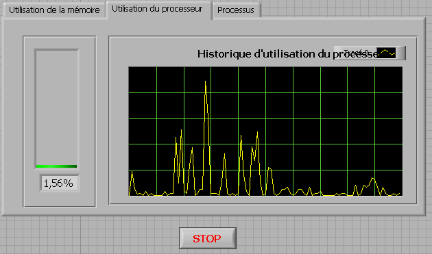
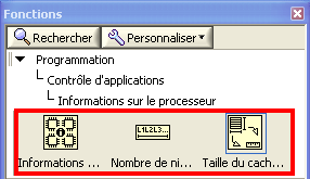
How to check the CPU usage and paging using LabVIEW
Hi guys,.
I build an application that is used to check the CPU usage and paging using LabVIEW. How can I do?
any help, suggestions or advice will be greatly appreciated...
Kind regards
Prashant
Hello
If you plan to build your app for Windows, you can use .NET classes. (System.PerformanceCounter), there is a simple example with LabVIEW:
C:\Program NIUninstaller Instruments\LabVIEW 2010\examples\comm\dotnet\SimpleTaskMonitor.llb
Also, you have several screws that you can use to verify information about the processor.
Kind regards
-
Programmatically insert step of ActiveX/COM using LabVIEW
Hello
I would like to be able to create sequences like the one set using LabVIEW.
This sequence has only 2 steps, a LabVIEW VI call and an adapter of ActiveX/COM call.
I was able to do using an adaptation of the code here: https://decibel.ni.com/content/docs/DOC-36337
However, I am struggling to add the step of the ActiveX/COM.
Any help would be welcome.
Thank you
Of course, there is a way, if you look for it

Since you have an existing 'Step' class object, you can also get a 'Module' object for her. Subsequently, you will need to specify that it is an ActiveX module. If you do not know which - probably you need to get the object 'map' somehow... Our case is simpler, so just cast to the ActiveX module and... to set certain properties like ServerId, ActiveXReferenceExpr and so on.
I've attached an example for you. Interesting thing is the ServerId - I just read this chain of the TS for similar action and reused it here so do not ask me how to get automatically
You will need to complete your 'properties' as 'file' - but I'll gracefully leave this work for you =.
Best regards
-
Time real ADC/DAC for SMPS by using Labview and USB
Hi all
I asked the Sales Department of this same question, so here's a two-pronged approach:
I am reserching a control algorithm for power switching, and so far, its performance simulations seem to be good. Now, the goal is to implement the circuit from the experimental data.
I've seen several NI USB DAQ boxes that seem to have the performance, I'm looking for (for example, the box USB-6211 a sampling rate and resolution I need).
The control algorithm uses the following mathematical functions: add/sub/mult/div/exhibitor and derivative/integral.
My question is this: is "strong enough" Labview take four-channel data 250Ksps, crunches the numbers in an equation and spits out the answer to an analogue on the channel, while time REAL? I'm looking for a rate of analog output of ~ 100 kHz.
Thank you for any suggestions you have!
-Rick
Hey,.
So if you were trying just to perform an input or output, then the box USB-6211 would certainly be able to treat it as the machine clock could manage the inputs/outputs, no software. However, what you are wanting to do, basically a feedback system, he will have to avoid (at least to a USB device) because you need to be able to specify Active which is the output. So, for this reason alone and the fact that you want out of 100 kHz, this device and the USB devices in general will be not an option any what software you use, LabVIEW or otherwise. On another note, you want to make sounds more like live update, not in real time, which is more on the jitter. Bottom line, for these kinds of requirements, you might need to move to an FPGA card, something like the NI PCIe-7841R would work. It's more expensive, but for your needs, FPGA will be the only option and it comes down to the latency of the bus, but also the response time of software. With FPGA, as shown in the first scheme of the following document, you basically close your software through hardware loop.
Basics of FPGA
http://www.NI.com/white-paper/6983/en
-Ryan S.
-
Good Aftrnoon.
My thesis is based on software developed by using Labview. Can anyone suggest the best way to write the main sections?
For example, how to describe the experimental flow? My ideas have been use explanatory, take the labview code print screens describing what each of the subVIs. Does anyone have experience in this field? Or if you can share a thesis based on LabView program written, it would be ideal for reference. Thanks in advance
Kiryl
If your project markers are not familiar with LabVIEW, then frankly they should not be monitored a LabVIEW project.
In the same way that you would not be supposed to literally print code of entire base of a project in a written language, you don't need to go into the same level of detail with a LabVIEW project.
You can document your code with system diagrams, annotate them extracts of interesting pieces of code, writing pseudocode to illustrate the feature.
-
Deal with failure when using LabVIEW 2011 and DSC MODBUS communication
I'm currently reading from operating records a PLC with MODBUS/TCP. I confirmed that the PLC will update the values and in response to a MODBUS communication correctly by using a third-party program called Modbus Poll. However, when I try to query the PLC using the LabVIEW shared variable engine, I am unable to read the values of the same addresses that I consult with Modbus Poll.
My installation is simply to a PC directly connected to the controller via Ethernet without a router between the two. I'm using LabVIEW 2011 SP1 with the DSC module.
I opened the Manager of distributed systems OR to display the State of all variables in the Modbus Library that I created, and I noticed that the ILO CommFail permanently the value 'true '. All other variables with a 'read' access mode signal "failure of process". I tried to restart the process and stop and start the local variable engine without success. I also restarted my computer several times to see if any services did not exist, but this does not appear to have solved the problem.
Finally, I resorted to listening to communications on the network card I have the PLC connected via Ethernet using Wireshark and found that while Modbus Poll communicates with PLC, number of MODBUS and TCP packet is sent and received. However, when using only LabVIEW or the DSM OR communicate with the controller, there don't seem to be any communication on the network card.
Something that may be interesting to note is that I could communicate with the PLC and to read values with the DSM just once, when I understood everything first what address I should be reading of. All of this has stopped working shortly after. Prior to this, 'CommFail' was not generally set to 'true' with my current setup. Thinking it was my firewall, I have since disabled my firewall, but this seems to have had no effect on the problem either.
Any help on this would be appreciated.
So, I thought about it. It turns out that the IP address of the server i/o MODBUS must be set to the address of the MODBUS slave, not the local computer. The address of the i/o MODBUS server is defined by the navigation in the Explorer window projects, expanding the variable engine shared library for MODBUS and right click on the server MODBUS (for example Modbus1) item and select Properties.
In addition, the addresses seem to be shifted by + 1.
Thanks for the tip so.
-
Go to the PHP website using Labview 8
Hi people,
I'm writing a vi LV8 to retrieve data from a Web site. The first site I've played with just had a text output so a simple:
-OpenTCPConnection (for 'www.hpc.ncep.noaa.gov')
-WriteTCP:
-line 1: 'GET heat_index_MEAN/hitable_east.txt '.
-line 2: "" Host: www.hpc.ncep.noaa.gov".
-line 3:
-ReadTCP
It worked perfectly fine.
But this isn't really the data I want. I want the data displayed on the Web site:
http://forecast.weather.gov/MapClick.php?W0=t&W1=TD&W2=Hi&w3=sfcwind&w3u=1&W4=sky&W5=pop&W6=RH&W7=th... 96 & textField2 =-77.48167 & site = all & unit = 0 & dd = 0 & bw = 0
But, when I try the same calls I get the error messages like:
Query HTTP/1.0 400 Bad server: AkamaiGHost Mime-Version: 1.0 Content-Type: text/html Content-Length: 216 Expires: Sunday 12 August 2012 17:40:25 GMT Date: Sunday 12 August 2012 17:40:25 GMT connection: close
Bad request Bad request
Your browser has requested that this server could not understand.Reference #7.9f931160.1344793225.0
I don't know enough about HTML or PHP to tell if I have a HTML or PHP problem; and what I have to understand to move forward. More precisely:
-can you tell if it is a PHP or HTML problem in my code?
-If Yes, which?
-I can access a Web site (which uses PHP) LabVIEW?
-what I have to learn more about PHP to proceed?
-J' tried to send a command "OPTIONS" of HTML, but I received very similar eror messages (not a quesstion)
-the site has an XML option that displays data as text/XML, but it also seems to use PHP, if I get the same errors with my code (not an issue)
-any ideas on how to use labview to read data from this site?
Thank you, in advance...
-
Complete equipment of simulation using LabView, Multisim, and MAX (easy answer accepted!)
Hello, all!
Sorry, I'm new, but I checked around for a definitive answer on this, but I'm not 100% sure. I learn LabView for a physics of upper-division course. We use hardware (DAQ - MX) and a mixture of laboratory equipment - mainly stuff such as voltmeters, oscilloscopes and test setup with simple components. I also work with NIM instrumentation, but that's secondary to my needs here. So, when I'm away from the school, is it possible to make a complete simulation of my classroom work using LabView, Multisim (for my model) and the measurement and Automation Explorer (for the acquisition of data-MX)? I know I can create a circuit and drop it in Labview, but I'm not sure on the acquisition of data. I hope for what is a "seamless" reconstruction of what I do in class. I can't take a simple 'yes' or ""; as long as I know it's possible, I can find the solution.
Thanks for the help!
I wrote 'sim' screws in many situations where I need to work away from the hardware store. I think that MAX has a few features, but you may be limited in the types of signals, you can simulate.
For my sim screw, I make a copy of the original VI with ".sim" added file name. I also change the icon in a characteristic way to identify the version of the sim card on the BD. In this way the two VI have the same connector pane and are interchangeable on the BD structure. disable the diagram can be your friend here. Inside of the VI of sim, I generate the signal in any form I want. You can also add additional if necessary controls.
Lynn
-
zedboard Xilinx Zync 7000 interface using labview
Hello
I'm doing my thesis in Zedboard for the development of a test for DDR3 memory and verification. For this I need to set up a base of dedicated on NI Measurement Studio LabVIEW graphical user Interface.
Theme: Algorithmic Szudy of test set-up for DDR3 SDRAM with a Xilinx architecting.
Here, I made my algorithm Xilinx SDK. But I need to create a graphical interface using labview. To run these programs. Please let me know how I can do this.
1 or is it possible to directly access the SoC architecting using Labview. If yes how?
2. or if I have to do the coding of Xilinx SDK and how do I run this code using Labview?
Please give me a detailed answer. As I am new to labview. I m not understanding how to start with. If you have any design example please share with me.
Thank you best regards &,.
Nithin Ponnarasseri
No you can not grow directly in LabVIEW and deploy this program to the Board of Directors Zync. NOR has their own material base platform Zync (cRIO and myRIO) but the tools to target these tips are specific to the hardware implementation OR and will not work with other hardware. Develop an interface for another hardware platform is a lot of work and must be adapted for each unique flavor to a new hardware platform. And NEITHER does not support this for other devices.
If your option will be to develop an application with the SDK Zync for Zync ARM controller and provide a form of communication interface (serial port, TCP/IP, or similar) to this application you can send commands to LabVIEW for your embedded application.
-
How to control an electric motor using LabVIEW?
Hello
is there a simple way to control the rotation speed of an electric motor (12V) using LabVIEW?
I have an idea how to achieve this using the card OR measurement, its not that cheap. Any ideas?
Maciek.
-
Strange behavior when using Labview to collect data from Tektronix oscilloscope tds8200
I hit a wall in trying to understand this one. The problem I have is that my application will not start the oscilloscope when it should.
I use an oscilloscope Tektronix TDS8200. My goal is to collect data from the oscilloscope using Labview waveform. First of all, my program initializes and configures the oscilloscope; This part of the program works very well.
The second part of the program begins the acquisition of data with the function 'Tktds8k Start or Stop Aquisitions.vi', which is to press the button run on the scope. The function "tktds8k to Waveform.vi" is used and should ideally return data, which I connected to a waveform playback graph.
When I run my program, the first part runs without a problem, but as soon as the program comes to the service get the waveform, the run button in the scope, which is green when running, turns off; the program then expires, and no data is collected.
Here is where it gets weird. I went through the debugging to try to understand this point, and I put breakpoints on the beginning and get shape wave functions so that I could scroll through the last part of the program. The program continues with the departure function, and the button run in scope is green. The breakpoint for the function get the waveform is reached and when I press on continue, turns the Run button and turns it off then back on almost immediately. data are collected, the waveform graph appears and the program ends without error.
I thought that the timetable could be the problem, so I did the program wait as long as five seconds between the functions of start and get the waveform and that did not work. I also tried to move the start function to before the configuration functions and remove start completely; no method worked.
is there any ideas on why, the program works when I enabled breakpoints and isn't when breakpoints are disabled? I'm sure there is an easy solution, but I was not able to find a solution.
I have attached a pdf that contains information about the functions of the Oscilloscope (tktds8k.pdf), and I have also attached my program.
-
TestStand deployment error Code 1055 when using LabVIEW storage VIs
After a few days of playing with TestStand deployment. I have final stalked the VI which was the origin of this error.
He was using the LabVIEW storage screw to save data in a TDM file.
My work around at the moment is to use a Wrapper VI and call this VI by reference.
In this way the deployment TestStand cannot detect the Sie of storage.
I'm using LabVIEW 8.6.1 and TestStand 4.1.1 does anyone know if this issue was address TestStand 4.2?
It seems that the upgrade can be worth it.
Simon,
After investigating the matter further, I found that we had already encountered this bug. It has been fixed in 4.2 TestStand and LabVIEW 2009 I tested your files with 4.2 TestStand, LabVIEW 2009 and everything built successfully without any hiccups on the way.
-
How to use Labview for measuring the reflectance at different wavelengths automatically
Hello!
I'm using labview to communicate with MS257 (a monochromator). If I do not use Labview, I have to use the hand controller (set a wavelength from 300 to 1100 under a grating (a total of four grids).) It takes a lot of time. So I want to use labview to realize the automation. But I don't know how to do, I still can put only a wavelength as a command for MS257, not making any difference.
Does anyone know how to deal with this?
Thank you for your time.
So where are you stuck? It is a fairly common task. Inside of a loop, you can increment the "xxx" and build a table of responses. Look at the Format function in the chain and a knot of shift register/feedback.
Maybe you are looking for
-
Do you want me to go to Chrome?I can't find the FireFox button, I see the icon but that has not helped me.I'm trying to figure out how to work with the ad - ons, but not having not much of help. Every article I read gives instructions for push the bu
-
HP Mini 1000: HP mini 1000 obtaining bios password test failed
HP mini 1000 get bios password check failure fatal system error stopped CNU9162D2D Please help cannot get into bios or open a session 1151nr model
-
Hello So about three months ago I had a problem with my HP mouse and browser. both were glitching on screen and does not allow me to type consistently or right-click (to copy, paste, etc.). After seeking help from technology College friends, HP reps
-
I want to comment on an idea for a new feature in Windows.
original title: 'click green '. Dear Microsoft, I thought of an idea today what I call 'green click '. It is a system of click energy rating on the browser. When the cursor passes over a link, it turns green, for example, or orange. When the curso
-
The older module does not appear in all: debugging #addons
I Developer Edition installed (v51) and some add-on for Firefox, with maxVersion 41.0 value I activated the installation of the add-on unsigned and was able to install and use. However, it does not appear on everything: debugging #addons and at the b