ARB waveform
Hello
I would generate an analog arbitrary waveform, for example a step function where the voltage increase 1 V each step where the tension is for awhile. A signal or analog example 5 and 0V for awhile. You really I use analog in the end. Currently, I'm trying to make a waveform using the generator of signals VI. Unfortunately, I get only something a triangle signal. How can I keep the value? It should look more like a digital signal (at least in this example, but on the analog channel). I found no examples that help me. So if you know an example where the value is hold please really tell me.
Thank you
Verena
Well, first of all I want to generate a simple waveform but finally the waveform is more complex, so I can't use any standard, square etc step function.
The VI is in two parts. First of all, I need to generate an arbitrary analog signal that has a width of half of all 300µs (upper loop) pulse. Then I had to re-read everything that is visible on the chanel. I order a sensor that produces a signal itself.
So I had two problems:
1 generate a quick signal (upper loop)
2 re-read everything that is on the incl. Chanel signal produced in 1 (lower loop)
Thanks for the help
Tags: NI Software
Similar Questions
-
Data flow using two or more bands in RFSG SMU-5646R
Hello
I am a newbie in Labview. I'm trying to implement the multiplexing in frequency in Labview. Recently I tried to use two strips to transmit the text file, then I found the error in niRFSG write ARB Waveform on the FIFO session while trying to run the VI. I use Labview 2014 and SMU 5646R. Could you please tell me if the VST can be used to transmit/receive using two frequency bands at the same time? Is it possible for me to implement this FDM using SMU 5646R? Any response would be very useful for me. Thank you in advance.
Kind regards
Renita
Hi Vince,.
Thanks for posting of your code. I see what is happening here. You get errors because you're trying to generate two signals separated with 1 device at the same time. It is not possible. You need to stop/cancel completely 1 RFSG in order to start sessions to generate with the other session.
-
Do one own pulse square with FGEN
When I try to make a single pulse square in LabVIEW using FGEN with NI PXI-5412, I find that I get a result comparable to the attached image, a smaller pulse occurring immediately after the pulse of the witch you want. I use the attached VI (the upper window is the VI and the two lower windows are the two screws used in the composition of the main VI). Is there a better way to do it, one who has a cleaner production?
Thank you.
Hi William.Maier
To print a single pulse, using arbitrary signals mode and set the trigger mode "Single". This will display 1 duration of the specified wave.
I have attached a modified version of the example of shipping 'niFgen base Arb Waveform' who does that.
-
Export of multiple markers in mode of arbitrary waveforms
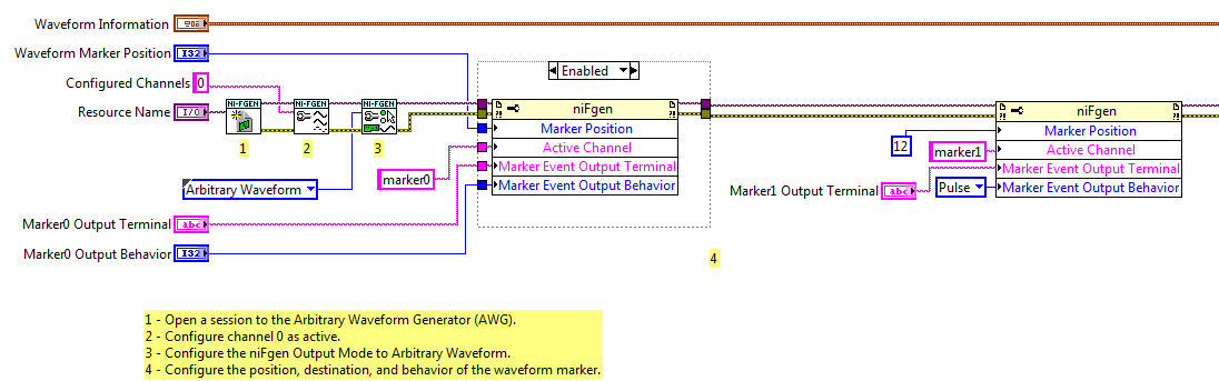
I use the example Fgen Arb Marker.vi waveform (in the examples of LV2011) as the basis for the production of markers and exporting to PFI0 and PFI1 on a PXI-5422.
I added a 2nd call of property node after the first configuration of marker1. The program runs without error, but only generates marker0. It seems that if I configure Active Channel as 'marker1' or 'marker2' or 'marker3' or 'marker4', the property node has no effect. I expect that subsequent calls must set up additional markers.
I used the script mode to configure several markers with my generator signal as well, but I'm trying to understand how things work in mode of arbitrary signals for some legacy code.
So just to summarize, things that I confused me more than before and during this thread have been:
1. lack of feedback of error/warning when configuring marker1-marker3 in wave arb mode
2. the general statement "a marker by segment" seems inaccurate given the script arb mode
3. script view arb is not mentioned in the PXI-5422 or PXI-5421 hardware specification
1. the Council supports 4 markers, numbered 0 - 3. So when you configure those, you do not get an error. When you configure marker4 you get an error because it does not exist.
2. I think you are right, that the statement applies to arbitrary waveform Mode, no Mode Script.
3. it's probably another problem of documentation. Script mode was not supported when 5421/5422 first came out, so my guess is that when a support because it has been added, the documentation was not updated.
Good luck
Marcos (not Marco
 )
) -
NOR-FGEN Arb Express reactivity
Hello
I'm playing with the VI Express NOR ANY Arb (with the NI PXI-5421) in order to learn how to create my own VI to generate impulses of the arbitrary. However, I find that when I click on "Run" in the Express window, my o-scope seems never to receive the waveform correctly. I use the sine wave sample and when I click on 'Run' with him put "Start continuous" the o-scope screen updates a few seconds later with a fragment of a sine wave, and it does not always up-to-date. The Test panels for the 5421 work very well with the o-scope, so I don't know what goes wrong.
Any help is appreciated.
Thank you
Billy MaierEDIT: Never mind, the problem itself. I don't know how to remove the wires.
Glad to hear that you have found an answer to your probem a little extra tip is to go beyond the express VIs as quickly as possible. The simplified interface they provide comes at a price. Banely, these screws will be nake laying of assumptions that do not always work in your favor.
Mike...
-
Viewfinder LUT vs exposure tools (Zebra / waveform)
Hi guys,.
Discussions on our new found access to MLUTs and the AE CINE was great, thanks for all the info fascinating so far. So forgive me if this has already been covered, but I have two questions:
(A).. .for MLUTs in the viewfinder to be of any practical, why use the waveform monitor and the Zebra reacts to the MLUT when applied, as opposed to the same as if the MLUT has not been applied to all? IE - as an image in the viewfinder as slog2 sgamut my Zebra / wave give me information of the exhibition which is very useful (next to my light meter) but when I apply, say, the REC709 MLUT of the VF, news of Zebra and waveform to adapt to the new image - so REC 709 points out, blow and my zebras tell me now that the parts of the image is blown... But I'm still recording to SxS cards like sLog2 sLog2 - so, in reality, this info is not get blown at all.
So what I mean: the REC709 MLUT is ideal to boost the brightness etc. in the viewfinder and makes the image easier on the eye than the image dark sLog2, but I always feel like my tools of exposure to expose properly for the image being recorded to the card (in this case sLog2). I hope that all makes sense... Accept others, or am I missing something here?
and the second point is:
(B).. .throughout all the upgrades for the camera by setting the number 2 zebras at 109% don't turn on for me in the VF, despite an image being obviously blown. No more than 108%, or 107%. However the zebras behave corectly to 106% and will show the 'Zebra lines' when the image is burned.
Is there a reason why 109% zebras does not illuminate, or am I missing something here too?
Thanks for all your comments guys - happy shooting.
Tom
-
How to open file audio waveform
We have a file on a USB audio waveform. iTunes will not play it... any suggestions or recommendations on another application to use or download? Thank you!
VLC download it here: VLC for Mac OS X
-
In case others were too curious, our fantastic Canadian camera Sony rep gave us this scale of waveform.
Currently, you cannot activate the display full screen, we are looking at this for a possible future update
Concerning
Peter
-
Number of averages for time waveform acquisition
Hello
It is on the configuration of the device - settings of the acquisition.
in the parameters of the collection file, can I know is there a way to feed the number of averages and % of overlap between averages aquire waving time.
Thank you!!
BR
Pattabi
In version 3.0 of InsightCM, we will support an average and overlap on the data of the spectrum Viewer. These settings will be applied only to the visualization of the spectral data and will not apply to calculations on the waveform or spectral data form.
This will meet your needs? Or are you interested in doing an average and are superimposed on the spectral data to then be used for calculations that are based on spectral data - such as 1 x Magnitude, etc.. ?
Thanks for the question.
-alan
-
Restart waveform immediately start trigger
I create a waveform 50 ms with an SMU-5451 in SMU-1078 chassis with a controller of SMU-8840 running Labview RT. The waveform is currently triggered by a pulse of a counter of data acquisition because the timing of the wave must be closely synchronized with data on the acquisition of data collection. However, this approach is problematic because it is difficult to produce a continuous of the 5451 signal when it is triggered in this way. If the waveform is exactly 50 ms long, will miss the start trigger. I can tolerate losing at the end of the wave, but I can't tolerate having a gap in the output, and I need the waveform to start exactly on the edge of outbreak of 50 ms. I can configure the 5451 to accept a trigger start and restart the wave immediately rather than wait for the current iteration of the waveform to complete?
I guess I could use a complete the 5451 event to trigger the acquisition of data instead, but I guess there is a way for me to do what I want.
Are you familiar with the mode "script"? You might be able to use this example script:
script restartWhenTriggeredScript

  Repeat forever

    generate wfm

    break on scriptTrigger0

      Repeat forever

        generate wfm

      end repeat

    end break

  end repeat

end of script
Basically, the idea is that, when it receives a trigger, it stops the execution of the inner loop and finish the iteration of the outer loop. Then it will start again from the beginning and to the inner loop.
Please let us know if that fixes the problem.
-
Arbitrary waveforms with LVM file
Before, to import a file of arbitrary waveforms to VirtualBench environment was carried out thanks to an option in the toolbar of the menu drop down and the Import Wizard allows import of files LVM. Since a more recent firmware update, it is now accomplished in the Panel containing the options for the function generator, but forced the wizard to import the files .txt and .csv only. Has anyone found how to load an arbitrary waveform as file LVM in the most recent update of the firmware?
Jesse wrote:
Before this function arbitrary waveforms, it was possible to load a file of .lvm for a waveform on the channel (1 or 2) and display it in the GUI of VirtualBench.
You can load a waveform in the ASM or another instrument in the VirtualBench GUI?
The only similar device that has VirtualBench is a waveform of reference for the scope, which was also added in 15.2. The post office announced that I linked above has a video showing this feature as well.
You have screenshots of previous undergraduate design projects? I still think that we are badly understand each other.
-
I read a sine wave using a data acquisition with a sampling frequency of 250 Hz. Once I acquire the signal, I get the component signal Y and multiply it by a factor inside a matlab script. I use the wave build function to retrieve the waeform and display it. If I put the component dt of my function to build in 0.01 waveform, this means that the signal is sampled at 100 Hz?
navinavi wrote:
If I put the component dt of my function to build in 0.01 waveform, this means that the signal is sampled at 100 Hz?
Not exactly. You are just lying to the display, which gives it something which has been sampled at 250 Hz and claiming that it was sampled at 100 Hz. If you filter on it or whatever it is in the frequency domain, everything will be far away.
-
Import MATLAB generated the file ascii in the Analog Waveform Editor
Hi all
I tried to create signals by the Analog Waveform Editor. I have some Waveform generated from MATLAB and recorded as ASCII files, following the instructions on this Web page OR, but it did not work properly. For example, if I produce a column to fill with 0.5 and import the file into the analog signal generator, all I get is a huge series of random number. I missed a few steps in the import of the waveform?
Thank you!!
Just for your reference, I could almost in half the size of your file just by saving as .hws. Also to answer your last point, you may have issues opening / importing your .txt file because it may have been opened in another program at the same time. Make sure that you have closed it in Notepad or Excel or other programs which may still be locking on the reference.
Kind regards
Jason L.
-
cDAQ-9263 modules do not allow independent generation of waveform
I have a client with a cDAQ-9178 crate with two 9263 modules. When it tries to start two independent signals on both modules build tasks, he gets an error in DAQmxWriteAnalogF64:
device cDAQ1Mod2:-50103: NI Platform Services: the specified resource is reserved. The operation could not be performed as indicated.
Extended Info:
Platform AND Services: The specified resource is reserved. The operation could not be performed as indicated.
Task name: cDAQ1Mod2AO
State code:-50103
It seems that it must be a driver bug-usually these "reserved resource" errors occur when you try to validate the task, but it comes from DAQmxWriteAnalogF64. It verifies that he can start two independent signals on two completely independent devices build tasks, but he cannot do it on two modules in his cage.
Is it a kind of witch-hunt with modules in a box? or a driver bug? He tells me that he has updated the driver until his "last from the website of OR" with no luck.
Thanks in advance!
The cDAQ-9178 has only a simple timing analog; output engine You can't have a timed analog output generators of waveforms of the task at a time. Unfortunately, the mistakes of 'the specified resource is reserved' are not more descriptive.
The call of DAQmxWriteAnalogF64 pushes the task as a 'reserve', which is where he tries to book the timing (and other resources) engine: the first task will succeed, but subsequent AO to the tasks will not be until the first has reserved resources.
The two tasks are intended to operate simultaneously at the same speed? You can put chains of two modules in the same task by using a string of physicalChannel as cDAQ1Mod1 / ao0:3, cDAQ1Mod2 / ao0:3 with DAQmxCreateAOVoltageChan.
-
SCOPE NI Y waveform versus time
Hello
I use NI PXI-5114 scope, how can I get the values of x (increment of time) of the measures I / O-> OR-scope for my chart.
Thank you
For niScope read, simply choose the polymorphic case that produces a waveform (or an array of waveforms for multiple channels) and that wire up to your chart. Waveform type data included the start time and sampling rate for the chart may include the X for you.

Maybe you are looking for
-
Where to buy a screen cheap for Satellite A30 151
Hello my laptop screen was broken and I want to get my country (Turkey) but it is expensive and I want to get another country.How can I get it? and what is the price for this?
-
Set up a network using WLAN Mini Card
I have a desktop HP Pavilion HPE 300. A friend gave me a WLAN 802.11n mini-map he got HP and never used. What drivers and adapters wireless do I need to use this card to set up my computer to the wireless network. This work of setting type will lo
-
I'm working on the code for a visual basic project, I'm working on that.
I'm trying to get my program to check if a file is opened, even if the program is closed and the there closure?
-
minimize, resize, close the windows, the buttons at the top right do not work in Chrome
I found several references to this problem, but all were dated in 2010, which suggests that there must be a solution. I use Vista Home Premium and something has happened in the last two months, causing these buttons allow to stop working - reduced, r
-
Packaging with some types of code errors
Hi all I have strange problems in packaging and running the application. Any time I get the functions to set the width/height/layout as shown here, I get the package. editField = new BasicEditField ("", "", 150, BasicEditField.EDITABLE |) BasicEditFi