Arbitrary waveforms
Hello world
I use the Modulation Toolkin do my thesis, specifically, I work with the driver NOR RFSG. The VI called "niRFSG set up generation Mode.vi" needs to set an option (the mode of generation). You can choose between a CW, arbitrary waveforms and a script. Well, I have to use the option of arbitrary signals but I do not quite understand, but that means. What type of waveform is generated? Where can I find more information about this?
Thank you.
Hi kantabra
When you use the method of arbitrary signals, you must set the IQ data yourself that is generated. I suggest you take a look at the example that accompanies the driver NI RFSG. You can find it through arbitrary waveform Generation.vi help - find examples - material IO - Modular Instruments-OR RFSG - arbitrary signal generation - RFSG
This example shows how to use this method with your signal generator.
Tags: NI Software
Similar Questions
-
Arbitrary waveforms with LVM file
Before, to import a file of arbitrary waveforms to VirtualBench environment was carried out thanks to an option in the toolbar of the menu drop down and the Import Wizard allows import of files LVM. Since a more recent firmware update, it is now accomplished in the Panel containing the options for the function generator, but forced the wizard to import the files .txt and .csv only. Has anyone found how to load an arbitrary waveform as file LVM in the most recent update of the firmware?
Jesse wrote:
Before this function arbitrary waveforms, it was possible to load a file of .lvm for a waveform on the channel (1 or 2) and display it in the GUI of VirtualBench.
You can load a waveform in the ASM or another instrument in the VirtualBench GUI?
The only similar device that has VirtualBench is a waveform of reference for the scope, which was also added in 15.2. The post office announced that I linked above has a video showing this feature as well.
You have screenshots of previous undergraduate design projects? I still think that we are badly understand each other.
-
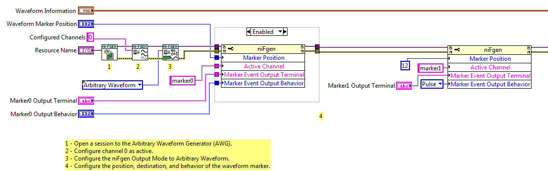
Export of multiple markers in mode of arbitrary waveforms
I use the example Fgen Arb Marker.vi waveform (in the examples of LV2011) as the basis for the production of markers and exporting to PFI0 and PFI1 on a PXI-5422.
I added a 2nd call of property node after the first configuration of marker1. The program runs without error, but only generates marker0. It seems that if I configure Active Channel as 'marker1' or 'marker2' or 'marker3' or 'marker4', the property node has no effect. I expect that subsequent calls must set up additional markers.
I used the script mode to configure several markers with my generator signal as well, but I'm trying to understand how things work in mode of arbitrary signals for some legacy code.
So just to summarize, things that I confused me more than before and during this thread have been:
1. lack of feedback of error/warning when configuring marker1-marker3 in wave arb mode
2. the general statement "a marker by segment" seems inaccurate given the script arb mode
3. script view arb is not mentioned in the PXI-5422 or PXI-5421 hardware specification
1. the Council supports 4 markers, numbered 0 - 3. So when you configure those, you do not get an error. When you configure marker4 you get an error because it does not exist.
2. I think you are right, that the statement applies to arbitrary waveform Mode, no Mode Script.
3. it's probably another problem of documentation. Script mode was not supported when 5421/5422 first came out, so my guess is that when a support because it has been added, the documentation was not updated.
Good luck
Marcos (not Marco
 )
) -
Simulate the analog output of arbitrary waveforms
Simulate it Arbitrary Waveform VI Express can be used to generate analog signals to the physical channels in analog output mode systems such as the NI 9263? I am trying to use the VI arbitrary signal generator to produce a signal used to excite the magnetic coils.
Why don't you just try and see what happens? As far as I know, it should work.
-
Hello!
Does anyone know how to add AWGN carrier generated using NI RFSG?
I know how to generate a signal CW using NI RFSG arbitrary signals mode (see attached file), but I have not found out yet how to add AWGN to it.Thank you!
Aina
Hi Aina,
I can always be understanding not completely exactly what you ask. So in my example I gave you, we add the additive white noise GAUSSIAN on both I and Q tables separately. What you are looking for is actually add noise to the signal after he was upconvertis. Does this sound right? With our equipment, it is not possible because the baseband I / data Q are mixed with the carrier in the material as the last step before that it is generated. To add the additive white GAUSSIAN noise after the signal has been on the carrier you would need a noise generator. The best you can do is add the additive white GAUSSIAN noise to the baseband I / Q, then upconvert it based on the carrier frequency, you specify in RFSG. Let me know if this has been helpful for you.
-
How to generate arbitrary waveforms FRO meter
Hello
I have a problem in the generation of the wave as shown in JPG below. Need to generate digital waveforms 2
1. with the help of counter0 - digital waveform will be with pulse 60 (58 - good pulsations and 2 empty pulse)
2. with the help of Freqout - digital waveforms should be to synchronize with a 40 pulse signal 2 signal should be high for then 5 impulses.
I tried model digital generation with Boolean 2D table convert to digital waveforms. But somehow, I couldn't have expected waveform.
If someone could help me in this problem.
Thanks in advance
Vijay
FREQ Out is not able to generate either of two waveforms - it can only generate continuous pulse trains. In fact, even one of the complete M-series meters would be unable to generate your "Signal 1" - you must use the 2nd meter to the signal from the door.
Supported boards of series X buffered output of the counter and could therefore be used to generate a waveform. You can use Freq Out yet, but the X series boards have also 4 full meters if this should be enough resources such as Freq Out is not necessary.
Best regards
-
Hello
I would generate an analog arbitrary waveform, for example a step function where the voltage increase 1 V each step where the tension is for awhile. A signal or analog example 5 and 0V for awhile. You really I use analog in the end. Currently, I'm trying to make a waveform using the generator of signals VI. Unfortunately, I get only something a triangle signal. How can I keep the value? It should look more like a digital signal (at least in this example, but on the analog channel). I found no examples that help me. So if you know an example where the value is hold please really tell me.
Thank you
VerenaWell, first of all I want to generate a simple waveform but finally the waveform is more complex, so I can't use any standard, square etc step function.
The VI is in two parts. First of all, I need to generate an arbitrary analog signal that has a width of half of all 300µs (upper loop) pulse. Then I had to re-read everything that is visible on the chanel. I order a sensor that produces a signal itself.
So I had two problems:
1 generate a quick signal (upper loop)
2 re-read everything that is on the incl. Chanel signal produced in 1 (lower loop)
Thanks for the help
-
Build waveforms of the discrete points
Hi all
I'm doing a signal generator with the possibility of an arbitrary waveform.
I have a graph with some sliders on it that you can move you like (only in the direction Y, not X) of these points, I would like to
to create a 'soft', waveform, which is a waveform with lets say 500 points so the edges is not so rough. I have attached a few photos showing what I
have and what I would
 ) (I have the discreet and I would finesse of waveform as the exit)...
I tried tinkering with FIR filter, interpolation, spline function, but I don't think it's the way to go because of the low amount of datapoints that I start
with, but perhaps that these functions could be a second step in the process?
This curve is something the user will draw whenever he starts the program, that's why I'm kind of limited to max 10-20 points all about to create a waveform
similar to that of the image.
Hope you understand my problem and are able to help.
Thank you
Concerning
Tommy
Here's my try... My quick entry was an array of cursor ;-)
If you run in a loop the operator GET direct feedback.
Why you don't like flutes?
Sidenote: If you choose force for interpolation, you have a Pisa as print :-)
-
PXI-5421 generating an arbitrary signals on the fly
I have a card PXI-5421. I need to generate an arbitrary waveform with different frequencies. I need to have a trigger to switch between Forms of waves of different frequencies. I use the script to do this. I'm not able to update the frequency of the next wave on the fly without stopping the program. In other words, can I download signals in real time? The code is attached.
Hey Kakrott,
You should be able to achieve this with your PXI-5421. The example of 'switch between the waveforms FGEN"in the examples of LabVIEW makes something similar to what you're trying to do. As explained in the documentation: "this example shows how to switch between two different wave forms while generating, using updated data every time." This example uses a trigger to change what waveform is generated.
-
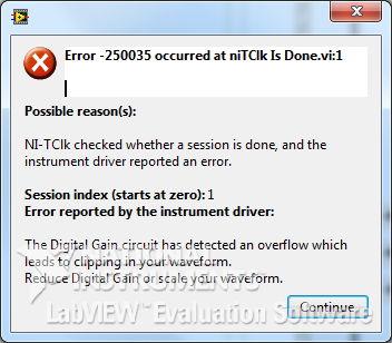
Digital and analog gain in Script mode
Hello.
5422 module can change the voltage Vp-p order of 05:54 V.
But when I use the property node - digital Gain, after setting the 1.1 V and return to its previous value (V 1.0) occurs the following error:
And when generating a signal of amplitude of 1.1 V signal very distorted.
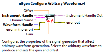
In niFgen configure Arbitrary Waveform VI it is a Gain parameter to control the standard signal (which I understand). Is there something similar for the Script mode?
How to access the analog Gain?
And in general, how to properly use the analog and digital gain in Script mode?
I apologize for possible errors, but the example is not yet complete.
Max O.
Developer of software and engineering,
TeSLa.
Hi max_i,.
Since the ownership of digital Gain help file:
"Specifies a factor by which the digital signal generator multiply data generated before the conversion of an analog signal in the CAD." Saving digital greater than 1.0, the product digital time gain the data generated must be in the range ±1, 0 (assuming that the floating point data). If the product exceeds these limits, the signal generator cuts out the output signal, resulting in an error. »
Digital gain requires the data, being always standard-1 to 1V. The output of 'Ladder' to 'normalise Waveform.vi' here is generally superior to 1, which causes this error 250035. If you search for the property similar to the entry of 'Gain' on the ' configure Arbitrary Waveform.vi ', I advise to use the 'Gain' on the tab 'Arbitrary signals' property in the property node.
Looking at your code, it seems that you try to build pretty standard signals (sine signals). Is that this will change in the future to more complex waveforms? If not, I wouldn't recommend watching one of the examples in the example LabVIEW finder, I find "Sequence of Arb basic Fgen" quite useful. If you want to make scripts as well, I would recommend the example "Fgen Arb Script".
Thank you
David B
National Instruments
Technical sales engineer
-
Ideas on how to create a sine wave between 0 and 10 V with NI 5412?
Hello
I tried to create a sine wave from 0 to 10 volts on a 5412 OR. I have 2 problems and I have a question:
(1) I can't generate a waveform with lag, even when using the examples of NEITHER.
(2) the value of the offset, that I can set the camera is of +/-25% range of amplitudes. Do I have to create an arbitrary waveform myself?
(3) in the brochure it says I can get 12 v peak-to-peak. Does this mean that it is between-6 and 6, or it is between 0 and 12?
I would appreciate it if I could see an example.
Thank you very much.
Hi, several notes:
(1) the peak to peak voltage is 12V. For example, it can operate between 0 - 12V.
(2) the shift of 25% limit is for a given wave. That means assuming that it will create a wave, it cannot compensate for 25% of the beach. The solution is to create an arbitrary wave (e.g. a sine between 0 and 10 V) and the function generator to create rather than attempt to compensate for a sine wave.
Thanks for the help though.
-
That means the 14-bit resolution
Hello
The '14-bit resolution' refers to the data entry for the PXI-5412 (via niFgen_CreateWaveformFromFileI16 or niFgen_CreateWaveformFromFileF64), the output of the PXI-5412 through channel 0, or both? To clarify a bit, I know that niFgen_CreateWaveformFromFileI16 reads a 16-bit data source values, but the values contained in these 16 bits must be within a range of 14-bit?
Some background information... I use a system that contains a PXI-5412. I am executing the example C code and change it to some arbitrary waveforms. I have a Spectrum Analyzer, connected to the output of the PXI-5412 and tries to understand the results. I use a data file that contains a chirp waveform.
Generate data of chirp via Matlab. I can save try it in different formats, but began to record off the coast under 16-bit. In my application, I load the data using niFgen_CreateWaveformFromFileI16 and start the generation. The output is fed to a Spectrum Analyzer, but the result doesn't look like a sizzle. However, if I record the same data on as a double and use the SAME code (do NOT change the niFgen_CreateWaveformFromFileI16 function), I see a Twitter. This result leads me to my question.
Moreover, it is in the talk discussion page wrong forum. You must go to the site below next time:
http://forums.NI.com/T5/signal-generators/BD-p/310
Thank you
-
Swing cut into reason NI 9263 map
I have a NI Compact RIO Setup with the analog output NI 9263 card. I generated Pulse Width Modulation (VLOW = 0v, VHIGH = 10 v) frequency 100 HZ using LabVIEW 2012. I have verfied the signal with the reach of agilent. IAM see exactly 100 HZ (VLOW = 0v, VHIGH = 10 v). But unfortunately, it has not worked when I sent that signal to my speedometer. When checking with my field of agilent, I discovered that there was a shift to shift. Now my VLOW is 6v and my VHIGH is 10V. This means that my pulse amplitude reduced from 10v to 4V. The speedometer works OK when a similarly square wave amplitude is applied by a function generator.
Do you know what is the reason for this? He had internal tensile resistant with 9263 card will put a divider between NI 9263 and entry of pottential speed meter?. internal pull up resistant of the circuits of the speed indicator is 1 K ohm.
I would like to know if there is a workaround.
Thank you guys. After a bit of research, I am convinced that the problem is caused due to the incompatibility of the impedance. The real solution will be to buy an arbitrary waveform generating the map which can be impedeance up to 10 K OHm. Genarating a PWM of AO card is a very bad idea. Again this depends on the instrument under test requirement
-
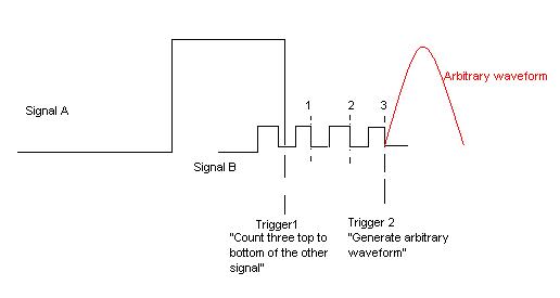
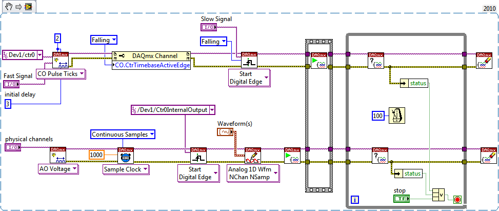
Trigger multiple channels of PFI
Hello world!
I want to create a trigger depends on two signals incoming (from external function generators) of PFI. Both are square waves, but the frequency is different. My wish is to trigger the slower from the top down as three top to bottom the faster and then generate an analog output. The picture is hopefully more descriptive than my words.
I use a NI DAQmx 6713 card. It doesn't matter if the solution is a LabVIEW VI or a C++ writes the text file. All the recommendations of good tutorials or similar is welcome. I managed to trig the arbitrary waveform after signal A or B, but I can't have the status of "County/wait three impulses."
Best regards
K. Berg
Hi K Berg,
It is possible with the 6713 - you will need to use a meter of output to generate the trigger for your AO signal. Use your signal slow to raise the output of the counter. Use the fast signal for the time base of the counter with an initial value 3 delay ticks. The meter goes off on the edge of your slow signal and once that was triggered will generate a pulse after 3 ticks of the fast signal.
Best regards
-
The vi in the file (mt_nifgen_am_ssb_signal_gen.vi) can be used to generate an acoustic one AM SSB signal through a 5401 pxi and labview 2012 student?
If not, can someone recommend another example vi the vi above would be reduced 80% development time, as I am just starting and have no experience with labview. If it can be implemented, how? I'll ask for help to the wiring in the sound card later. Thank you!
Hi Groundflight,
It would depend on the function generators, you have at your disposal. The 5401 is a standard function generator who wouldn't be able to write to arbitrary waveforms. In others, it can only generate sine waves, square waves, trianglewaves, etc.. The frequencies and amplitudes are adjustable, however only in the software. This means that you can change these settings, but only when you plan to do. The trick with this is that you will be limited by the resources of your computer and clock rate.
With an arbitrary signal generator, you can predefine the wave you want out, load this waveform on the amount of memory on-board card and generate. The Modulation Toolkit will help you create the waveform you want to / out of load on the arbitrary signal generator.
The Modulation Toolkit is generally used with our RF equipment (AM, FM, FSK, PSK, MSK, PAM, etc..) Radio-frequency signals) However, it should be able to be used with our signals arbitrary maps as well. With the Modulation Toolkit, you provide the basic band information or message signal that must be modulated with the carrier. This is specified by the type of waveform in LabVIEW. You need to convert your audio of this type, however, I have no experience in doing so.
Kind regards
Jason L.
Maybe you are looking for
-
Satellite L755-M1E6 - cannot find this model on the UAE UNITED - Middle East site
Dear friends, I bought a new model of Satellite (L755-M1E6) in Abu Dhabi.But I could not see this particular model number in the United Arab Emirates UNITED - Middle East site.Normally, we could see that the model number is in the format - "L755 - 00
-
I want that my shop, found in card apple
in apple card, I can't find my shop, I have my shop position in card apple
-
Impossible to rename files in Windows 7 "cannot find this item.
Since the last batch of updates of Windows 7 (KB915597, KB3179573, KB3115475, KB3177723 and KB915597), suddenly I am completely impossible to rename the folders, even newly created. When I try, I'm greeted by an error message indicating: "Cannot find
-
A desktop HP 1050 may throw a stand-alone Copier?
Hello Recently bought a Deskjet 1050 and really like it. My daughter needs a casual Copier for the child insurance papers, etc., but she doesn't have a computer. It seems to me that this all-in-one will be just copies by lighting it and using the cop
-
Creative Suite 2 (CS2) "PowerPC Applications.
I recently downloaded Creative Suite 2 and he repeated to me that I can't open the application because the PowerPC Applications are no longer supported.Is it possible for me to still use CS2 as I need?Thank you.