How to generate arbitrary waveforms FRO meter
Hello
I have a problem in the generation of the wave as shown in JPG below. Need to generate digital waveforms 2
1. with the help of counter0 - digital waveform will be with pulse 60 (58 - good pulsations and 2 empty pulse)
2. with the help of Freqout - digital waveforms should be to synchronize with a 40 pulse signal 2 signal should be high for then 5 impulses.
I tried model digital generation with Boolean 2D table convert to digital waveforms. But somehow, I couldn't have expected waveform.
If someone could help me in this problem.
Thanks in advance
Vijay
FREQ Out is not able to generate either of two waveforms - it can only generate continuous pulse trains. In fact, even one of the complete M-series meters would be unable to generate your "Signal 1" - you must use the 2nd meter to the signal from the door.
Supported boards of series X buffered output of the counter and could therefore be used to generate a waveform. You can use Freq Out yet, but the X series boards have also 4 full meters if this should be enough resources such as Freq Out is not necessary.
Best regards
Tags: NI Hardware
Similar Questions
-
Hello!
Does anyone know how to add AWGN carrier generated using NI RFSG?
I know how to generate a signal CW using NI RFSG arbitrary signals mode (see attached file), but I have not found out yet how to add AWGN to it.Thank you!
Aina
Hi Aina,
I can always be understanding not completely exactly what you ask. So in my example I gave you, we add the additive white noise GAUSSIAN on both I and Q tables separately. What you are looking for is actually add noise to the signal after he was upconvertis. Does this sound right? With our equipment, it is not possible because the baseband I / data Q are mixed with the carrier in the material as the last step before that it is generated. To add the additive white GAUSSIAN noise after the signal has been on the carrier you would need a noise generator. The best you can do is add the additive white GAUSSIAN noise to the baseband I / Q, then upconvert it based on the carrier frequency, you specify in RFSG. Let me know if this has been helpful for you.
-
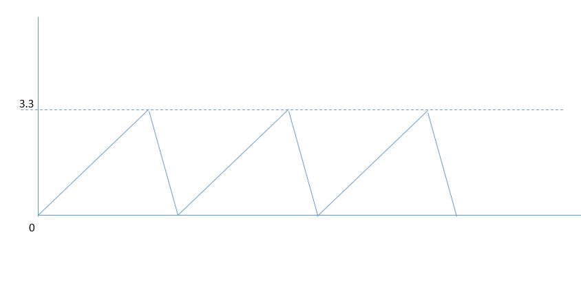
How to generate only positive sawtooth waveform?
Hello, I want to generate a waveform only positive saw tooth, from zero and ramp up to 3.3V and down than up to value zero and not swing at-3, 3V. is it possible to do in labview 11?
something like below.
Of course. What have you tried? Have you looked at the model of ramp function?
-
How generate the waveform analog multi simultaneously.
I use the relay Full.vi Gen to generate a waveform.
I want to create another form of wave and start at the same time.
Any suggestion?
Hi turbot.
The easiest way to make the two tasks simultaneously is to have two copies of this task in the block diagram. In LabVIEW, any function that has all its entries ready or a Subvi runs "simultaneously", so no additional real action must be taken to make them simultaneously. However, you must make sure that all entries of all your screws are to be executed simultaneously are ready at the same time (which means a set of functions that generate the wave does not need any input on the other). It's called the data flow model in LabVIEW. Read this for more information: http://zone.ni.com/devzone/cda/tut/p/id/6098#toc0
I would you suggest to use an other sub - VI for opening and reading your file (as well as use a different file for each reading Txt Subvi relay). You can also make your Subvi re-entrant. For more information on screw reentrant, refer to this link: http://digital.ni.com/public.nsf/allkb/98847B4E4C715E6D86256C59006B57CC
I would also say that you pass the path to the main file of your VI by using a control in your Subvi, rather than using the constant you have now.
-
Arbitrary waveforms with LVM file
Before, to import a file of arbitrary waveforms to VirtualBench environment was carried out thanks to an option in the toolbar of the menu drop down and the Import Wizard allows import of files LVM. Since a more recent firmware update, it is now accomplished in the Panel containing the options for the function generator, but forced the wizard to import the files .txt and .csv only. Has anyone found how to load an arbitrary waveform as file LVM in the most recent update of the firmware?
Jesse wrote:
Before this function arbitrary waveforms, it was possible to load a file of .lvm for a waveform on the channel (1 or 2) and display it in the GUI of VirtualBench.
You can load a waveform in the ASM or another instrument in the VirtualBench GUI?
The only similar device that has VirtualBench is a waveform of reference for the scope, which was also added in 15.2. The post office announced that I linked above has a video showing this feature as well.
You have screenshots of previous undergraduate design projects? I still think that we are badly understand each other.
-
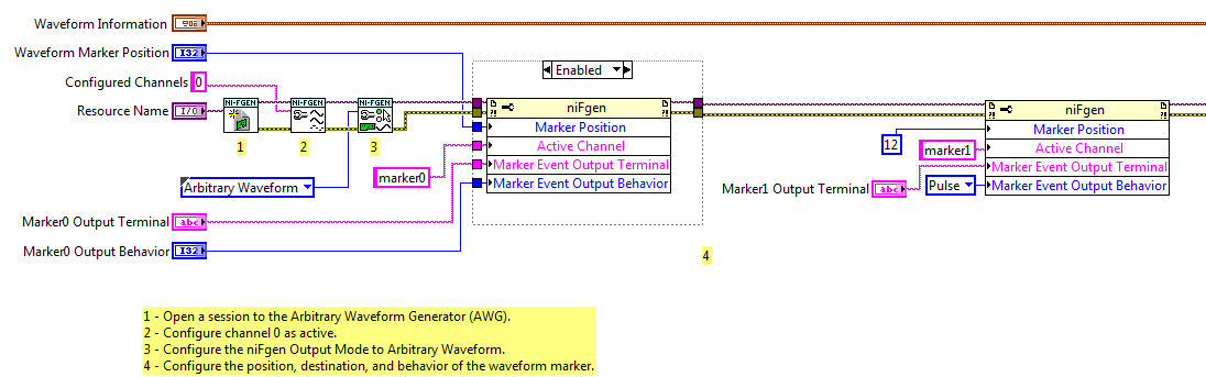
Export of multiple markers in mode of arbitrary waveforms
I use the example Fgen Arb Marker.vi waveform (in the examples of LV2011) as the basis for the production of markers and exporting to PFI0 and PFI1 on a PXI-5422.
I added a 2nd call of property node after the first configuration of marker1. The program runs without error, but only generates marker0. It seems that if I configure Active Channel as 'marker1' or 'marker2' or 'marker3' or 'marker4', the property node has no effect. I expect that subsequent calls must set up additional markers.
I used the script mode to configure several markers with my generator signal as well, but I'm trying to understand how things work in mode of arbitrary signals for some legacy code.
So just to summarize, things that I confused me more than before and during this thread have been:
1. lack of feedback of error/warning when configuring marker1-marker3 in wave arb mode
2. the general statement "a marker by segment" seems inaccurate given the script arb mode
3. script view arb is not mentioned in the PXI-5422 or PXI-5421 hardware specification
1. the Council supports 4 markers, numbered 0 - 3. So when you configure those, you do not get an error. When you configure marker4 you get an error because it does not exist.
2. I think you are right, that the statement applies to arbitrary waveform Mode, no Mode Script.
3. it's probably another problem of documentation. Script mode was not supported when 5421/5422 first came out, so my guess is that when a support because it has been added, the documentation was not updated.
Good luck
Marcos (not Marco
 )
) -
Hello world
I use the Modulation Toolkin do my thesis, specifically, I work with the driver NOR RFSG. The VI called "niRFSG set up generation Mode.vi" needs to set an option (the mode of generation). You can choose between a CW, arbitrary waveforms and a script. Well, I have to use the option of arbitrary signals but I do not quite understand, but that means. What type of waveform is generated? Where can I find more information about this?
Thank you.
Hi kantabra
When you use the method of arbitrary signals, you must set the IQ data yourself that is generated. I suggest you take a look at the example that accompanies the driver NI RFSG. You can find it through arbitrary waveform Generation.vi help - find examples - material IO - Modular Instruments-OR RFSG - arbitrary signal generation - RFSG
This example shows how to use this method with your signal generator.
-
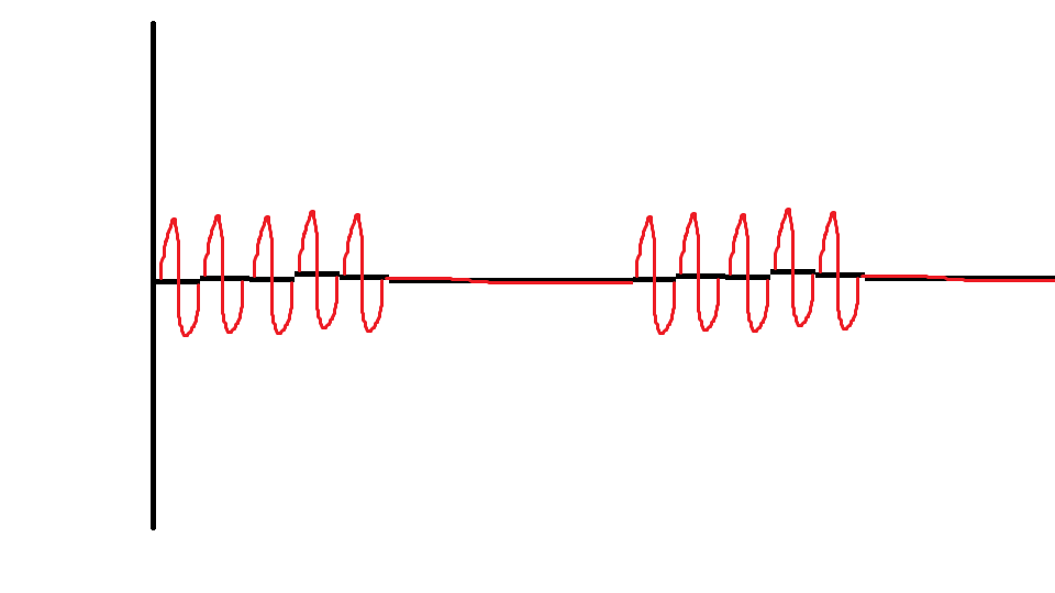
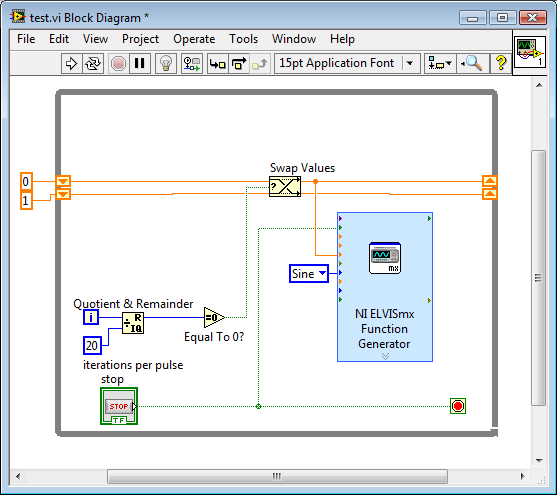
How to generate a pulse with the signal generator?
Hello
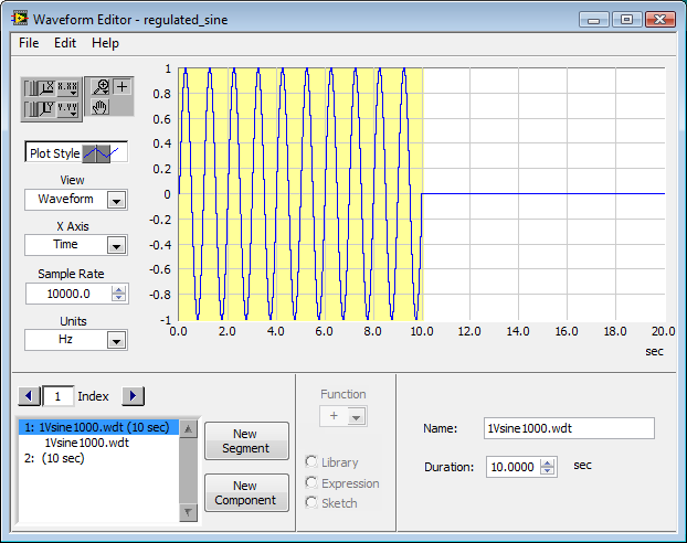
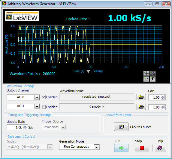
I would like to ask if anyone knows how to use the Elvis platform to generate a regulated pulse wave?
It should look roughly like the picture above. A sine wave with the regulation.
Anyone who can answer my question please respond to my post.
Thank you.
You are using LabVIEW to generate the waveform or using the Soft front panels? In LabVIEW, you can use the express VI generator function and specify the Type as "Sine". Then, simply change the amplitude of the sine wave. During the actual pulse, the amplitude would be what you want (i.e. 1 V) and while the pulse is idle, set the amplitude to 0.
If you use the soft front panels, you can use the Waveform Editor to create a waveform that includes a sine wave for the length of your pulse and then the values of '0' for the rest of the time. Then use this waveform in the flexible front of the arbitrary signal generator. Simply create a component of sine as the first part of the wave and then add another element to a level DC '0' for the rest.
-
Simulate the analog output of arbitrary waveforms
Simulate it Arbitrary Waveform VI Express can be used to generate analog signals to the physical channels in analog output mode systems such as the NI 9263? I am trying to use the VI arbitrary signal generator to produce a signal used to excite the magnetic coils.
Why don't you just try and see what happens? As far as I know, it should work.
-
Generate digital waveforms of high frequency
Hi all
I have some problems. Today, I am generating several digital high frequency waves with my DAQ (PCI-6251) card. The duty cycle of the waveform must be adjustable.
The required frequency is 100 kHz.
To do this, I have tried several solutions:
(1) I used counters in the acquisition of data to generate waveforms, and it worked fine. However, I have only two counters. In my application, I need to at least three waveforms with different cyclical report;
(2) I used a 'loop' and structures 'case' in labview to build the model of waveform and then feed them to the digital I/o. However, the problem with this solution is that the frequency of the wave generated cannot be high.
(3) I used a 'digital' generator in Labview to generate waveforms and then feed them to the digital I/o. In this case, the time base is from an external source (200 kHz). However, with this solution, the cycle is not adjustable.
Please give me some advice on how to make these waveforms. Your assistance is appreciated.
OK, so I may be wrong, but after mucking around for a bit, I realized that the regeneration should be automatic - in other words, if you a pattern to the right and then just leave your VI work in a while loop, you will find that the generation is continuous. Discover the correlation dig write metered in the finder for example Labview. You can leverage this as you get the cyclical report you are looking for. You can split the signal down what you write a single period consisting of a series of 0 and 1. In other words, if you want a wave of 100 kHz with a cycle of 20%, you write a pattern of digital waveforms a 1100000000 at the rate of 1 MHz. Using this technique, the resolution of the cycle will be limited by the on-board clock speed (80 MHz = 0.125%).
Let me know if this makes sense - I am unable to reproduce this on my desktop and have never had to do this before.
Cheers, Matt
-
How to generate a sine wave of table of values?
I have an array of points (values) around 1000. I want to draw them in different types of waveforms - triangle, sine, cosine, etc..
How ca I do that? For the waveform of triangle, I was able to split my table into 2 halves equal and draw the first half and the separately half second to generate a waveform of the triangle. But how to sine, cosine, Sawtooth etc.? It is a matter of urgency. Prompt response will be appreciated. Thank you
Hello
The VI in math palette is a polymorphic, it accepts the input also array.
attached a VI for your reference.
VI generates 1000 randon numbers and trace the sine and cosine wave.
-
How to generate the array Diagnostic Utility ADU for Esxi server
How to run Diagnostic Utility ADU or HP Insight Diagnostics HP Insight Diagnostics table to collect the status tables and logs data FRO an Esxi Server
How to generate the array Diagnostic Utility ADU for Esxi server
Example:
Download the package .vib here: http://vibsdepot.hp.com/hpq/feb2013/esxi-5x-vibs/hpacucli/hpacucli-9.40-12.0.vib
and place it on a store of data seen by the host...
Install it using the CLI:
software esxcli vib install d vmfs/volumes /
/hpacucli-9.40-12.0.vib Now run it:
~ # cd/opt/hp/hpacucli/bin
/ opt/HP/hpacucli/bin # . / hpacucli
HP Array Configuration Utility CLI 9.40.12.0
Detection of controllers... Fact.
Type 'help' for a list of supported commands.
Type "exit" to close the console.
=> ctrl all diag file=/tmp/my_ADUreport.zip ris = on = on zip xml = on
Generation of diagnostic report... done
-Online output
/ opt/HP/hpacucli/bin #.
my_ADUreport.zip in / tmp can now be downloaded from the host...
It could be that useful...
/ Rubeck
-
How to generate random numbers from 1 to 5
How to generate random numbers from 1 to 5
-1110340081
Thank you I ended up
-
DAQmx task start-up delay / quickly generate arbitrary output voltages
Hello
(Sorry, I m new to this forum and could not find a reasonable solution by using the search)
I develop a c# multithreaded application that generates a waveform in the 'background' using output buffering simultaneously, captures the images via a firewire camera and treat them. I have a second channel DA free that I would use when debugging a marker in real-time so that I can check on an oscilloscope which is the relative condition of simultaneous processes, i.e. output a voltage of 1 V while treatment step 1, 2 Volts to processing step 2 etc. or I would be out a short spike at some critical point. This is done using a task as
DA_Task_sgl = new Task();
DA_Task_sgl. AOChannels.CreateVoltageChannel ("/ Dev1/ao0", "DA0" - MXVOLTAGE, MXVOLTAGE, AOVoltageUnits.Volts);
DA_Task_sgl. Control (TaskAction.Verify);
DA_Task_sgl. Timing.SampleTimingType = SampleTimingType.OnDemand;
DA_Writer_sgl = new AnalogSingleChannelWriter (DA_Task_sgl. Stream);then, when I want to change the tension
DA_Writer_sgl. WriteSingleSample (true blood);
A similar technique worked pretty well using Traditional NI DAQ, but with NIDAQmx and the concept of task, it seems that a voltage of output value takes about 1.5 ms (also of time CPU) which is too slow in many cases. With Traditional NI DAQ two consecutive calls to AO_VWrite() may generate a COB with only a few µs endeavors instead. I guess that the delay in the NIDAQmx is mainly determined by start and stop work, etc.
Is there a way to avoid all this (in NIDAQmx) and more direct access to the underlying hardware?
(Please Don t tell me that it is a limitation of Windows, NOR-Trad code clearly shows that it was possible, clearly the thread may be interrupted during the output voltage, but is also my treatment, exactly what I want TO check with this technique, but that 1.5 ms the delay is still there!)
(Currently used card PCI-6014 with NIDAQmx 9.x, but I think that it s not the card which is itself too slow, I can get the update rate Analog > 100 kHz on the string of voltage waveform via DMA)
Thank you
Joachim
Hi fabwes,
The snippet you posted on request AO. This means that whenever you write we go and search equipment to generate tension. Your assumption is correct, the slowness that you see is because of the job template. Whenever you are calling WriteSingleSample the task is launched, the tension is out, and the task is stopped. I suggest the following code:
DA_Task_sgl = new Task();
DA_Task_sgl. AOChannels.CreateVoltageChannel ("/ Dev1")("/ ao0", "DA0" - MXVOLTAGE, MXVOLTAGE, AOVoltageUnits.Volts);
DA_Task_sgl. Timing.SampleTimingType = SampleTimingType.OnDemand;DA_Writer_sgl = new AnalogSingleChannelWriter (DA_Task_sgl. Stream);
DA_Task_sgl. Control (TaskAction.Start);
DA_Writer_sgl. WriteSingleSample (false / * since we are already started, this parameter is essentially ignored * /, tension);
This slight change gets the load to start the task of the road before start you writing.
-
How to generate an impulse to test short circuit in an inducer
Hello
IM new to labview and am in need of complete SURG - SURGE STRESS TEST
This test is intended to detect a short tour inter by applying a number of high
voltage pulses (or surge) for the selected winding.
Each pulse should produce one sinusoidal transient that eventually decreases to zero.How to generate the impulse using labview.
Hi Jessica,.
Please see the "pulse pattern.vi" function--> pallets of signal processing signal generation.
Otherwise, you can browse through examples of LabVIEW.
Kind regards
Srikrishna.J
Maybe you are looking for
-
Hi, when I brought my laptop hp compaq about 20 months ago, I was promised a free by Bing Lee update, well, guess what no upgrade never don't come across, when I contacted lee bing, they said to contact hp, so here I am and can't find where to go, do
-
my door opens to a cd in. what's up?
-
BlackBerry 10 10.3.1.1581 seems good but full of bugs
10.3.1.1581 looks great, but it has set previously reported and new bugs: 1. NEW: Cannot use TuneIn Radio for BB, the error message is "JavaScript Alert. Can't find an audio player taken in charge. 2 OLD: There's the Z10' day 1, not yet resolved. Pho
-
Problems of blackBerry Smartphones SMS - BB in a continent to use for the SIM of another continent
Hi all I travel constantly between two continents (Europe and Africa). I just had a new BB 9000 in Africa. My previous phone, a BB Pearl, was also gave me a few months in Africa. I used my European SIM in it and it worked perfectly (phone + sms + e-m
-
How to use the pc 610y system recovery CD
How to use the pc 610y system recovery CD