Arduino analog read PIN frequency
Hello.
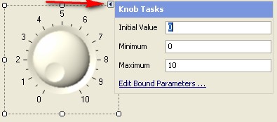
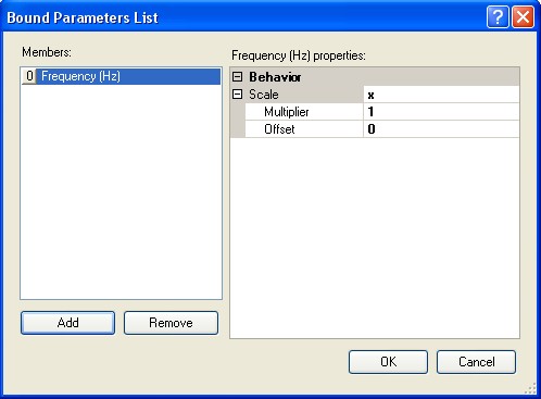
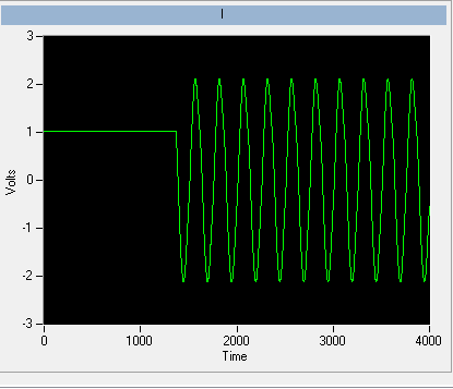
I try to convert the digital voltage (read of the analog pin on my arduino mega, an accelerometer) and perform an FFT/Spectral analysis to convert a volume from the frequency output waveform.
I'm having some trouble to accomplish this, with my release of the Arduino Pin Vi read as a double data of 16 64-real precision, which I convert a single waveform. The output of my spectral measurement through TFF (RMS) is a cluster of 1 d of 3 elements. When I have this thread to a waveform curve it changes just the values of Y (size) but often does not update the X axis at all.
Please help here is up to here a screenshot of my setup:
[IMG] http://i.imgur.com/WrzbX.PNG [line]
I've also attached the VI below.
Tags: NI Software
Similar Questions
-
Is it possible to read my frequency more frequently?
Hello
I was hoping I'd be able to read a frequency of 50 Hz (period time = 20ms) with three samples if my program had a cycle of 60ms (or at least two). Unfortunately, I can only recover a sample during this period.
I built a *.vi to experiment a little with this. He considers the time of a while loop a loop and allows the user to change the number of samples, timeout, etc.. As you might suspect I'm a beginner, and I hope that there is a simple way to solve what I'm missing.
Is it possible for me to acquire/closer more samples of the frequency to 60ms entry? Do I have to use solutions in time real (unavailible for me at the moment)?
Any help is appreciated!
Will be
Hi again
I had not included the (implicit) schedule Vi and this caused the problem.
-
PXI-6070E, how can I configure which are two analog input pins?
Hello
I'm reading 3 analog signals using PXI or 6070E simultaneously. I'm looking for on what axes correspond to what analog inputs? It's the same thing all the time, or should I set up?
For example, currently, the pines 68 and 34 are the + and - of the AI0 channel. But I can't find the rest.
Thank you.
How you are looking for the list of the pins? Look in the manual or in MAX, right-click on the device and select 'device pinouts. Ai0 is 68, ai1 is 33, ai2 is 65. The pins do not change. What changes is ending the pins to use if differential or single acquisition. For example, if you purchase a differential signal with ai0, you use pins 68 (ai0) and 34 (ai8).
-
Store (arduino) analog data in a 2D matrix
Hello
I need to store analog data in a 2D array. I can't use 2 for loops, because I get complete data at the end of two loops. So I need to use 1 loop for and store my analog data in an 8 x 8 matrix in this loop. (A for loop so I can store data at run time and I don't have to wait until the end of the loop for).
If you an idea how I can get it please let me know.
OR
Initialize a 2D array
integer divide the 'i' of your loop by 8.
Serve the rest as the quotient of the row index and column index and replace data at this level of R/C with the new data.
-
How to read the Serial Arduino data using labview VISA?
Hi =). Im a beginner work reading data series from an arduino but im facing... Lets do it step by step
I built a voltage divider circuit which gives from output
from 0 to 5V. The output of this circuit is sent to a 0 analog input pin
of a Committee of Arduino Duemilanove.(1) Firstly, I connected the cable to connect to my laptop USB the Arduino.
(2) I went to start-> control
Control Panel-> system-> hardware-> Device Manager. Check the Ports (COM
& LPT). In my laptop I can see USB Serial Port (COM4). Now I know only in
LabVIEW that I must read the data series COM 4.(3) to the side of the arduino, here's the code to read changes in voltage
entered to analog pin 0. The last line of 'delay' determines the sampling
Rate of how we want to taste the output of the voltage divider:int potPin = 0; Select the input pin for the output of the voltage divider
int val = 0; variable to store the value from the probevoid setup()
{
Serial.begin(9600) (9600); Opens the serial port, establishes the rate of 9600 bps data
}void loop() {}
Val = analogRead (potPin); read the value of the voltage divider
Serial.println (Val);
Delay (10);
}I slightly modified the basis series reading writing VI... I have
attached the block schema used with comments. Basically, I tried to read
data series, divide by 1023 and multiply by 5 to graphic voltage
variations of the voltage divider circuit. But Im not getting
the correct voltage output values. The value of the tension just keeps go
0 and coming again, as shown in the photo.Could you guys please guide me on what went wrong?
Thank you!
-you read the data, even if there is no data on the port. If 0 bytes are read => «»
-in the case of false, you resources VISA wired for the output of channel tunnel?
-There is no close VISA at the end of the VI resources
-you're not a loop this VI reading bytes
I added an addaption of your VI that you should give a try maybe

-
Analog value read with DSC Module Modbus
Hi, I have a Delta PLC with an AD converter module. I use the four analog channels and in one of them, I have a thermocouple which displays temperature data on a microprocessor thermocouple meter. However, I want to display the data in Labview. The controller communicates with labview through the DSC Module of labview with success, but I am not able to read the data. Looking forward to your help.
Found the solution. addressing to the modbus master was different for this model of plc, so I looked up the address for delta plc Modbus and the analog read list has been a success on labview.
-
Problem in reading the PWM signals in myRIO 1900
Hi guys,.
I work with myRIO to generate PWM pulses.
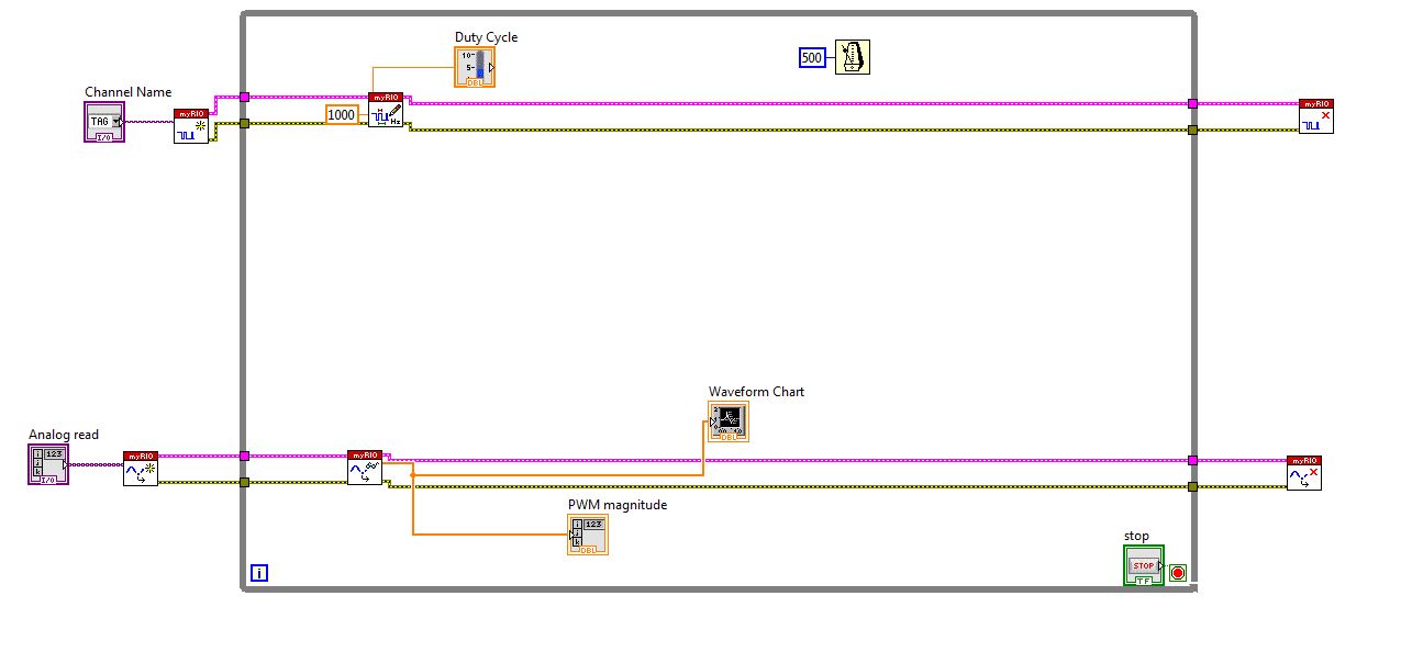
Here is the block diagram of my circuit.
I connected external to the analog input pin PWM pin. So I can watch the PWM pulse in the waveform table.
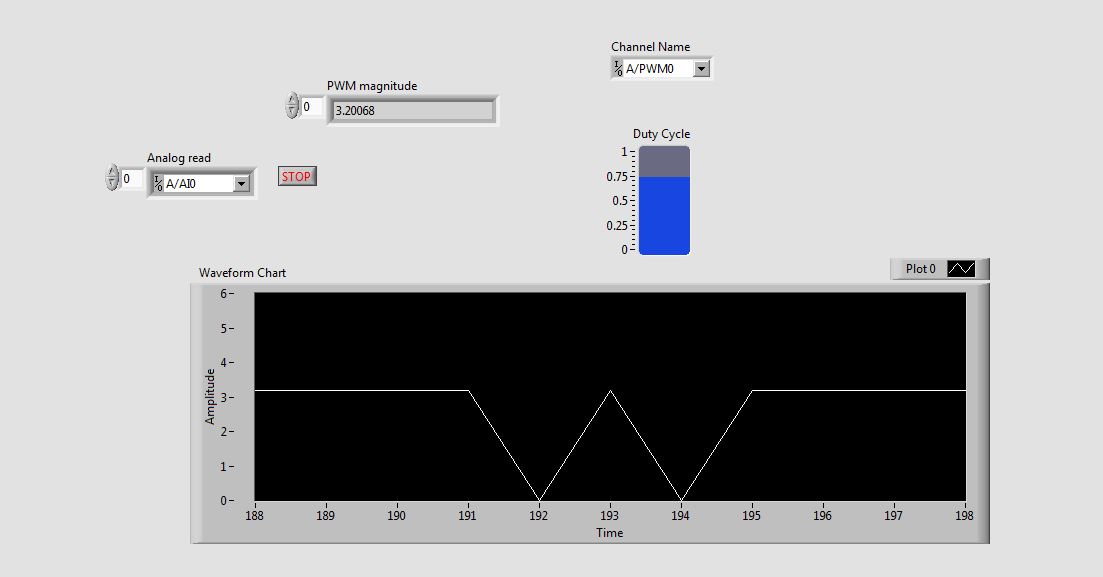
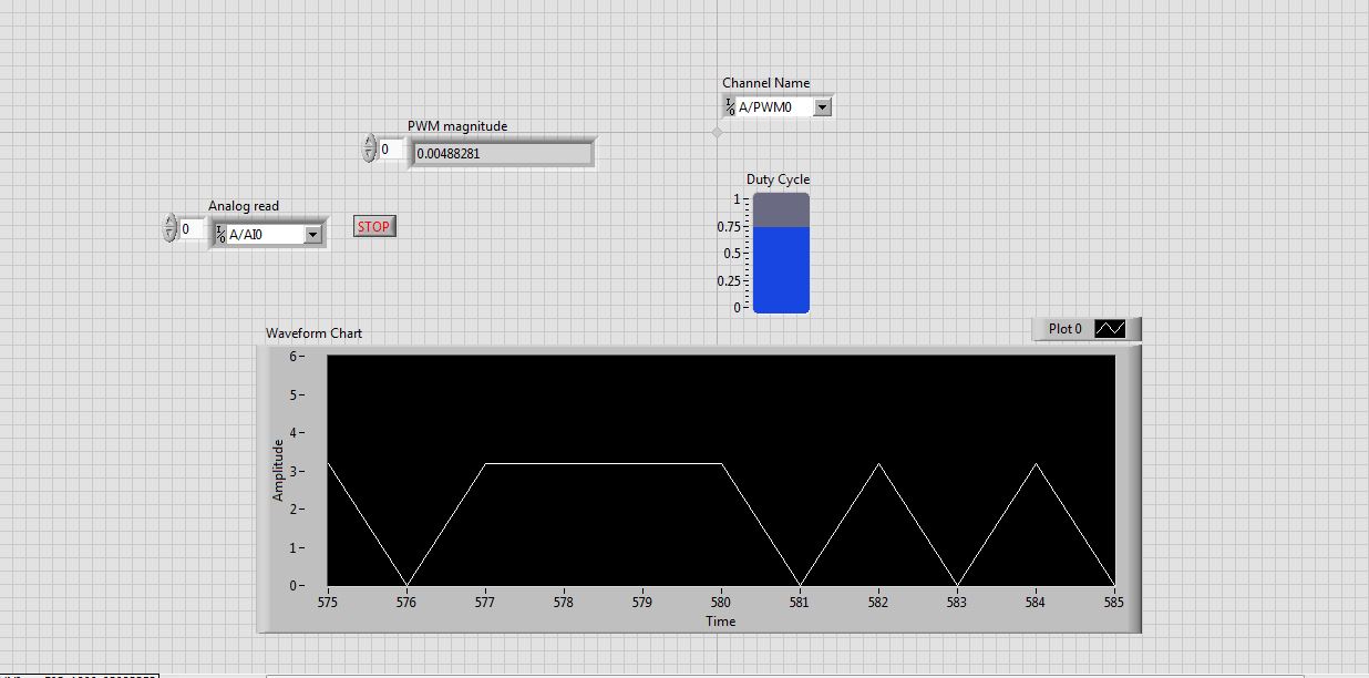
But the waveform is not clear. This is as shown in the screenshot.
See that the waveform is not correct. When I'm watching the same PWM pulses in the CRO (cathode ray Oscilloscope, oscilloscope real in the real world), I get exactly the waveform. that is, the PWM pulses are generated correctly. But the analog read is unable to read the PWM pulses.
I faced the same problem with the pin of analog reading earlier when I read the input voltage. Is not give continuous reading of the voltage input.
Please guide me how to read these impulses via analog read.
Please tell me at what frequency range, I can use this myRIO to generate impulses?
I am able to use 40 kHz?
Hi rcs.
The desired pulse frequency is 10 KHz. My sampling rate must therefore 100 kHz, which is not possible in data acquisition mode. There is another problem with the myRIO. Only AI0, BI0 and CI0 has n-sample mode. The analog input pins is still have no n-sample mode. But in my project, I need 4 pins of I in n-sample mode, which is not possible. In addition, the sampling rate should also be favourable, which does not happen in my case. We can say that this is a disadvantage of myRIO with data acquisition mode.
The only alternative to solve this problem is to use FPGA in myRIO.
He can taste a 25nS rate.
But little complexity is there -
Labview digital frequency measurement speed
I use a USB-6210 device to measure frequencies of 50 to 1000 Hz I need to connect the frequency every 50ms. I do this for a while loop in labview using a measure of frequency of 1 meter in labview and save the express data using VI. Each iteration of the loop takes at least 60 to 100 ms just read the frequency within the loop. How can I increase the speed of measurement in Labview?
PraveenB,
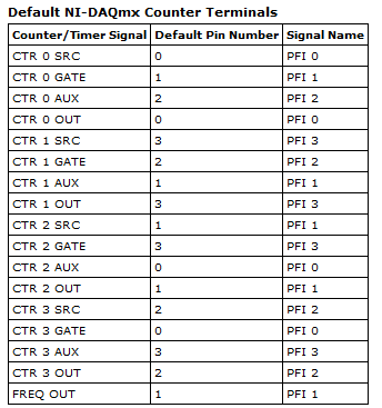
Here is a table of the terminals of the meter and associated PFI lines. It is available in the NI-DAQmx help. (http://digital.ni.com/public.nsf/allkb/CCDFC93878BD8781862570FC00559980?OpenDocument)
Default meter terminals OR DAQmx
Counter/Timer signal By default the PIN code The signal name CTR 0 SRC 1 PFI 0 CTR DOOR 0 2 PFI 1 CTR 0 TO THE 1 PFI 0 CTR OUT 0 6 PFI 4 CTR 0A 1 PFI 0 CTR 0 Z 3 PFI 2 CTR 0 B 2 PFI 1 CTR 1 CBC 4 PFI 3 CTR 1 DOOR 3 PFI 2 CTR 1 TO THE 4 PFI 3 CTR 1 OUT 7 PFI 5 CTR 1A 4 PFI 3 CTR 1 Z 2 PFI 1 CTR 1 B 3 PFI 2 FREQ ON 8 PFI 6
When you choose 1 meter in the channel to create VI it automatically reserves the door which is PFI2. If you use the counter 0 PFI 2 will work well. Even if you use the 1 meter, you can use anything but 2 PFI.
-
PXI-6133 Pulse frequency output and input with DAQmx
I am trying to set a pulse meter output frequency task and read this signal with a frequency counter input task input pulses. I use a 2 PXI-6133, each connected to a BNC-2090 case has. I want to output a square of a certain frequency with the task frequency meter pulse output and then read the frequency of this signal using a task of cost input frequency. I don't know how to property set up these tasks, or how to define which device to use for each heap. I don't know what terminals on the BNC-2090 is the counter of entry/sortient channels correspond to them because that is not displayed in the documentation of the PXI-6133 or documentation of BNC-2090.
Please see the attached VI for my attempt to put this in place. Currently, I get two errors:
(1) error-200452 took place at the property Node DAQmx channel meter Test - referred to as property is not supported by the device or is not applicable to the task.
2. the error-89136 at DAQmx Start Task - specified route cannot be met because the hardware does not support.
If I remove two channels of property DAQmx where I try to put the terminals for the counters, while the program is running, but then I know not what terminals on the BNC-2090 meters are connected to! This causes the DAQmx read for the cost in the tasks of frequency to timeout because it does not detect a signal.
I would really appreciate the help to properly configure these tasks and determine what terminals on the BNC-2090 case has the task of counter will work on.
I see a few problems in the code originally:
- For your CI task, you type is defined as a counter entry > frequency. But on the node property of DAQmx channel for this task, you modify the CI. Property of PulseWidth.Term. It should be CI. Freq.Term. set the entry regardless of the PFI line you do not want the input signal on. Tip: you don't have to type the name of the device in at all. Enter "PFI0", it's the same as "DevN/PFI0" since the unit has already been specified in the DAQmx Virtual Channel Create function. The name of the device, leaving aside will make your code more flexible where you decide later to change the name of the device.
- Maps of the S series, such as the 6133, do not have the same flexibility to change the output terminals of tasks of meter you might find with M or X series device. Page 83 of the S series manual watch what signals can be extracted to PFI lines - Ctr0Out is not one of these. Instead, Ctr0 out is, by default, pin 2. Cabling to a BNC-2090 6133 is certainly difficult to understand out (probably because the 2090 was designed to work with the materials of the E and M series), but if you compare the pinout of a PXI-6255 0 with the 6133 pinout connector, you will notice that they are essentially a match 1-1. Pin 2 is PFI12 on the 6255, so I assume the same for the 6133. All this to say, Ctr0Out always appears on the pin 2/PFI12 for the 6133 and you therefore cannot change the output terminal that your code is trying to do, having for result error-89136. Remove this node from the property altogether and the error should disappear.
-
measurement of frequency for ELVIS
I use Elvis and I want to measure the frequency of an analog input signal.
I use this program I found in a manual form OR.I'm using LABVIEW 8.0.
The problem is that the program is not read the frequency. No mather how often I try to read always indicates r = the same thing.
I have attacheted the program below.
Americanu22,
A couple of things that you will want to consider:
1. to ensure the frequency information is correct, you must be 2 sampling * [highest frequency in your Signal].
2. you can consider an ongoing acquisition with a configuration like this (' this example can be found in Help "" example Finder under material input and output "analog measures DAQmx'):
Good luck!
Kind regards
-
How to operate continuously the ' frequency with digitizer step-down converter external vi "?
Hello
I use SMU-5663 on SMU-1075 chassis. My goal is to use "step-down with digitizer external .vi" in order to run the SMU-6901 frequency continuous step-down converter. To do this, I added a while loop to the provided sample (see file attachment). The problem is that the while loop does not change; the program stops as soon as its launch.
Is there anyone who can help me with this you problem?Hello
The 'get frequency response' VI aims to help correct the answer of the step-down in the acquired data. The response of the step-down changes only with frequency and reference level. In your VI, you are in a loop when you call 'Get frequency response' but do not change the frequency or level baseline for the release of the VI will not change.
To use the external digitizer, you want to adjust the center frequency and level in DAMA reference, read the frequency response and frequency step-down converter win in DAMA, to acquire data starting from the external digitizer and correct using the frequency response of the step-down, and win. You can loop through the acquisition and treatment portions until you change the central frequency or reference level.
-
Measurement of frequency with the NI 9402
Has anyone successfully was able to measure the frequency in SignalExpress with the NI 9402 module? I have the 9402 connected to a tachometer (on a centrifuge) which puts a TTL signal. For now, I can get the light input line to work. (Right click on the project, acquire signals: DAQmx Acquire: digital input: input line.) When the tachometer completes the first round, light or the 'blip' lights indicating the sensor then goes back to the shore for the rest of the round. I would like to read the frequency of this "blip" instead. I can't understand the required parameters in Signal Express. I tried (right-click project, acquire signals: DAQmx Acquire: entry of meter: frequency) but maybe I do not have the correct settings. This centrifuge works usually between 0 and 3 hz. I have attached a picture of what I have. I am doing this correctly, with incorrect parameters? Or is there a better way to do this? I need to read Hertz over time. Thank you!
Hi Choover,
Even if you use the 0 meter to measure frequency, your singal acts at the door of the on-board clock source to measure the length (and thus frequency). This is why you must use PF1 to connect to the door of the meter. You can learn more about how DAQmx takes measurements of meter in any manual of cDAQ chassis: http://digital.ni.com/manuals.nsf/websearch/2C061605E17C7D04862578D200677B90
Brian
-
SignalExpress frequency control?
I have a PXI-6713, and I try to use SignalExpress to generate and get out an analog waveform with frequency controlled by the user. I think it's a simple task; I want just one button on my front panel that will allow me to select the frequency of the output wave.
I have a block 'create the form to analog wave' and a block "DAQmx generate the waveform", so I am able to output a fixed waveform. It's that I get, if. It doesn't seem to be an option to add the frequency command directly to the waveform to create step. I also tried to use a block "making the scale and conversion" to treat the waveform after creation, but it doesn't seem to be a direct way to change the frequency.
Am I missing something obvious? Asking too much SignalExpress? I do this in a regular VI instead?
Hello VTChris,
Thanks for posting on the forums! You're not too ask for SignalExpress, it's just that your application requires a feature of SignalExpress which is not commonly used. First of all, you have at least SignalExpress 3.0 is installed? With the release of SignalExpress 3.0, we added the functionality of the operator Interface.
LabView SignalExpress Help: Operator Interface
Operator interface select view"in the menu bar. The Toolbox with available controls should appear in the upper left corner. Place a button control to the bottom and click on the arrow icon to configure the properties of the control. You want to change the related settings for link control for the frequency step setting create an analog Signal.
Be sure to enable the operator Mode when you have finished configuring the button control. Let me know if you encounter any problems with this.
-
The data read into the buffer HAVE lack samples at the beginning
I use a box USB-6251. The program implements two channels of AI (read I and Q) on a single task and one channel on another task. The channel uses the ai\SampleClock as its clock, so that both are synchronized. C creates a digital pulse periodic rising edge (a clock basically) which is used as a trigger on an external function generator. The signal from the unit after going through some material, external signal processing is ultimately what is read by the channel of GOT it.
We know from the relevant signals, they seem to be correctly synchronized scope. IE, the analog signal to read arrived on the channel of the AI of the acquisition of data more or less instananeously when the trigger is activated. If there is a delay, it is of the order of microseconds.
However, when I read in the buffer of HAVE (repeated FiniteSamples), waveform, I always come back has a section of samples at the beginning that seem to be returned of the first actually read data-point (see attached image). This delay is of the order of milliseconds (it varies with each series).
I want to totally eliminate this delay. The signal should be a sinusoid which begins to sample 0 and is continuous through until the last sample read.
I put the code below.
Installation program:
Create analog read the task
analogReadTask = new Task ("analogReadTask");Create the virtual channel for the component I
analogReadTask.AIChannels.CreateVoltageChannel (initParams.AddrI.ChannelAddress, 'I', AITerminalConfiguration.Differential,-4, 4, AIVoltageUnits.Volts);Create the virtual channel for the Q component
analogReadTask.AIChannels.CreateVoltageChannel (initParams.AddrQ.ChannelAddress, 'Q', AITerminalConfiguration.Differential,-4, 4, AIVoltageUnits.Volts);To set the clock for the analog readings
analogReadTask.Timing.ConfigureSampleClock (string. Empty, initParams.SamplingRateHz, SampleClockActiveEdge.Rising, SampleQuantityMode.FiniteSamples, Totalechantillons);Create the mult-channel drive
analogReader = new AnalogMultiChannelReader (analogReadTask.Stream);
analogReader.SynchronizeCallbacks = false;pulseWriterTask = new Task ("pulseWriterTask");
Creating a digital output channel that provides the trigger to the U/S system
pulseWriterTask.DOChannels.CreateChannel (initParams.AddrUsTrigger.PortLineAddress, "US trigger", ChannelLineGrouping.OneChannelForEachLine ");
pulseWriterTask.Timing.ConfigureSampleClock ("/ SampleClock/AI/Dev1", initParams.SamplingRateHz, SampleClockActiveEdge.Rising, SampleQuantityMode.ContinuousSamples, samplesPerPulse);
pulseWriterTask.Stream.Buffer.OutputBufferSize = samplesPerPulse;
pulseWriterTask.Stream.WriteRegenerationMode = WriteRegenerationMode.AllowRegeneration;pulseWriter = new DigitalSingleChannelWriter (pulseWriterTask.Stream);
pulseWaveform = new DigitalWaveform (samplesPerPulse, 1, DigitalState.ForceDown);
pulseWaveform.Signals [0]. The States [0] = DigitalState.ForceUp;analogReadTask.Control (TaskAction.Verify);
pulseWriterTask.Control (TaskAction.Verify);
From reading:
analogReadTask.Start ();
Start writing the digital pulse, however it will not start
until the AI/SampleClock begins, so implicitly synchronizing the two tasks
pulseWriter.WriteWaveform (pulseWaveform, true);analogReader.BeginReadWaveform (Totalechantillons, readerCallback, analogReadTask);
Result (should be a sinusoid from end to end)
Always seems to solve these problems, shortly after their validation.
The problem has start the digital task AFTER the analog task. In the small delay between the two lines of code running, read analog had already begun, and so some of the impulses of the AI/SampleClock were missed by the task. The order of departure between the two tasks of switching solves the problem.
-
Problem writing data analog and entry of informed
Hi, I created a labview program that acquires 3 analog inputs (2 current and 1 tension), encoder out of whack angle and 4 temporary sensors. The Analogue inputs record against lunatics of an engine angle, once the engine has reached the point dead high simulateously in a single file. In another temperature record since signals file they are a lower sampling rate. Both files at the same time record by using the structure of flat sequence to the duration of the pulse encoder TDC events. The program works well with simultaneous recording.
However, I believe that in the file of analog inputs, the current readings are by crank angle but channel voltage readings are not. There a lot of zeroes inbetween pressure readings as if DAQ is not intervene for the tension. I can't understand why my program does that because the analog all the readings are in the same time of the sample and analog read the task.
I tried a program separate labview using only express DAQ and have the same 3 channels and saves the data in a file of lvm - it works even at the same pace. I do not wish to use Express functions in my program since fast flow and writing, he will miss values due to the explicit functions opening and closing of files (explicit writable) and creating the same physical channel (in daq express).
Please can someone help?
I have attached my program and a sample file entry.
Thank you very much
Notay
I think your problem is that you are indexing column 2 for voltage instead of rank 2. That's why you have only three elements in this table in the cluster.
![http://i.imgur.com/WrzbX.PNG [line]](http://i.imgur.com/WrzbX.png[/IMG])
Maybe you are looking for
-
15 - f010dx: Notebook is less than 2 months old and now won't turn on.
I have a HP Pavilion 15-f010dx it's a little less than 2 months and is rarely used for light work. This morning I went to for use and the computer has been insensitive. I held the power button down and run to make sure that the computer was not "slow
-
Can I enable BITLOCKER for any particular drive? for example D: drive, unit.
I can activate BITLOCKER for any particular drive? e.g. D: drive, unit. Without specifically put on for my system disk, IE the drive on which windows and other program files are located.Do I necessarily need to make the score, if I want to activate
-
Hello New owner of a T3-710 here and can not say that I am happy. No items in the box similarly not a simple guide for the connection. The only thing was a document showing how to connect the hard wired keyboard (not Applicable to my version) or plu
-
HP Deskjet 3070 will not print black.
I have a HP Deskjet 3070 and recently brought a few pack hp ink 364 ink combo from Amazon. The well installed ink cartages. When I try to print in black continues leaving as Faded or not at all. It's strange look I just made them. The printer seems t
-
Hello Need help as I used to be a Home Basic to windows 7 on my PC. I went and signed up for the free update to win10, but omitted from the waiting list and force the upgrade to 10. The problem started when my hard drive started to act up and had to