asynchronous IO with PCIe-6535e and DAQ - mx
Hi people:
I am trying to explicitly define and use either async or sync I/O using a PCIe-6535e DIO with DAQ - mx card. Nowhere in the acquisition of data-mx vi can I find the adjustment means either async or sync I/O. Does anyone know of an explicit vi reference say examples that I missed when this is discussed and or fix.
Also, assuming that I learn how to set the ack/write to the map mode, which defines the functionality and the strobe effect of the PFI pin which act as out of my data / data in banner? I can see that things like width pulse, delay etc. can be defined, but how to define? Or do I have to declare another channel with DAQ - mx and these control me manually. I tried, without real success.
For example, it would be really useful to do.
PFx pin _________-----------___________
xxxxxxxxxxxx XXXXXX (0xe7) line0:7
For the data from the card.
and
xxxxxxxxxxxxx xxxxxxxxxxxx (0xCA) line0:7
PFx pin ___________-----_______________
For the data of the car. In this case I'd be strobe the PFx in my FPGA.
I'm a bit confused as DAQ - mx does not seem to give me the command that I need to set the e/s mode, and I can't find any explicit
mention as to who, or how to properly synchronize the features of the PFI pin with my data from my vi.
Thank you.
Andrew
Hi Josh:
After discussions with our technical help academic rep, he suggested I oversample data and incorporate the pulse in the data. I did a little twist on the idea and I have attached a vi test I did. This creates just what I need. It'll work. I got def like other options, but it's good enough for now. If I had a devil FPGA I could move the world, and I can't do the code kludgy as that I joined. I would be interested in def in what other solutions that you or someone else could lead to the hearing.
Thank you.
Andrew
Tags: NI Software
Similar Questions
-
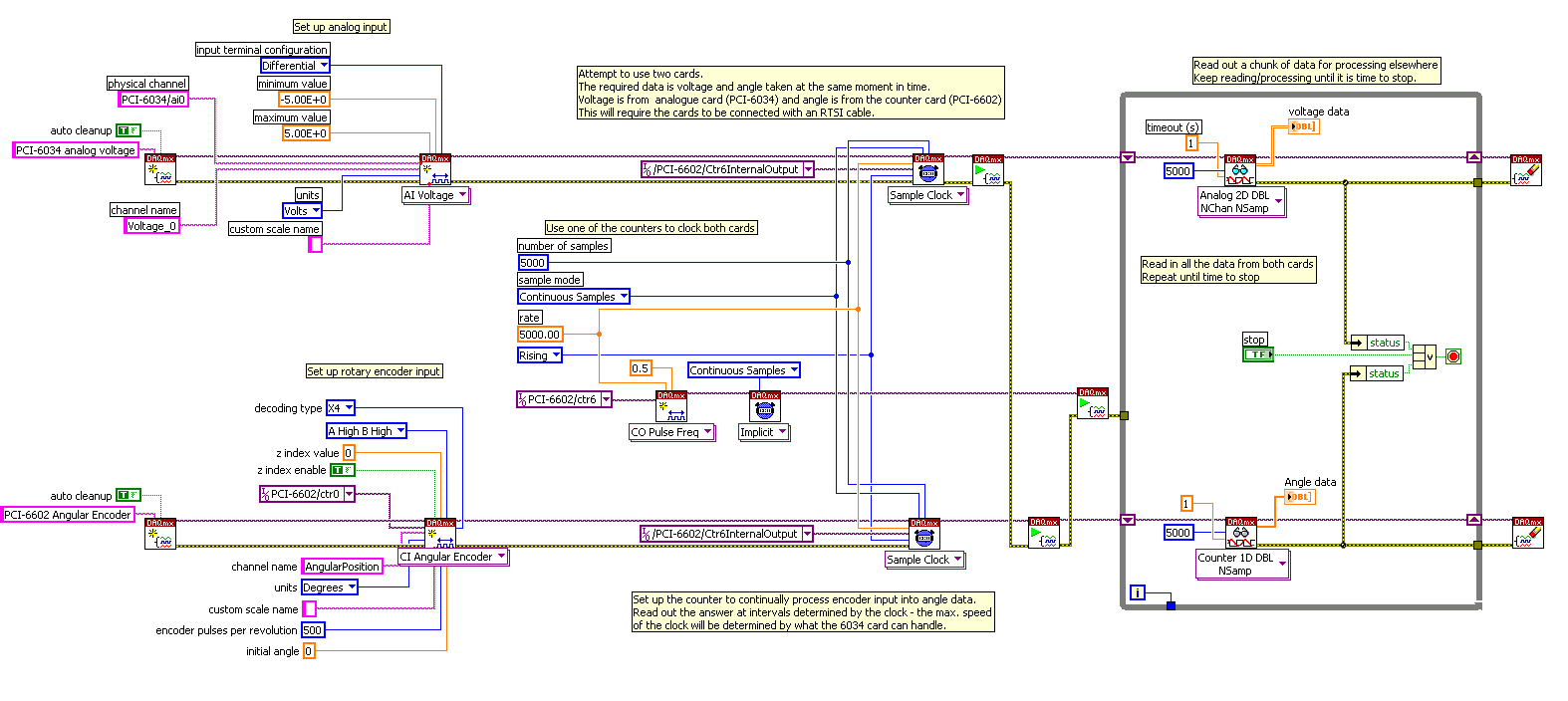
Cable RTSI with PCI 6034 and 6602. Test validation of LabVIEW code.
Hi all
Please could someone take a look at my code (LabVIEW 8.5) and tell me if it does what I hope it is? (!)
My goal:
To connect to analog to a PCI-6034 and data of angular encoder to a PCI-6602 tensions. I want my tension and angle data to synchronize.
My approach:
Both cards are connected with a RTSI cable and configured in MAX. One of the counters on the 6602 is set up like a clock. I think I use this clock to make sure that my angles and tensions are synchronized. I want to read in a load of data from two sources, treat it, and repeat.
The synchronization set is a little new to me - the code execution, but right now, I'm not sure if I get the sychronisation I need. Please what could someone comment if this sounds right or give me any advice for the improvement?
Thank you!
Ian
Sorry Ian,
This code was a bit thrown together then you might need to forget it. The table of construction was incorrect, and I don't quite know how it got there.
The output of the counter in the middle of your task is not doing anything. You can remove this, and as long as you had a single start task depends on the other that you already do and share all the same settings of the clock, which should start the task at the same time and keep it synchronized to readings.
On top of that my tip for better start synchronization would be to use a hardware trigger to start tasks. the start is so dependent on a hardware clock and not software.
Kind regards
-
problem of analog with PCI-6115 and BNC-2110
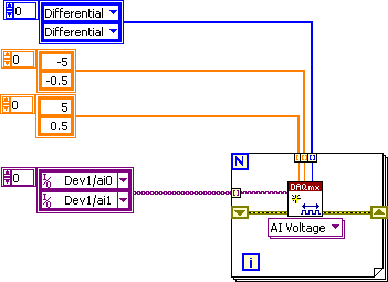
Hi, I have an acquisition of data PCI-6115 and BCN-2110 connector card I want to measure continuous analog voltage. Now I can permanently measure the intensity of light laser of photodiodes through channel 1 and get the reference through the 0. Then I can get the harmonic signals by the multichannel lock - DAQmx.vi. However, I also want to simultaneously detect another analog signal in channel of gold voltage 2. The problem is: Channel 2 voltage range is approximately 0.3 mV to 6 mV which is significantly lower than the other channel 2 (0 - 10V), how could put different prescription by channel continuously and simultaneously acquire all data?
I found that Dennis Knutson has provided the solution a year ago, which is listed below:
In the solution, it should be arrays of strings, lines, patterns, but I do not know how to apply it to my case. Is there a suggestion or another solution?
Thank you very much!
You have the autoindexed exit task and is not correct. Try the code below.

-
Question related to the entrance with pci 6221 and SCC 68 analog
I use 6221 PCI and SCC 68 analog read of voltage between the terminals of the drain and the source of a transistor. The drain is at 0 Volt and source is connected to 5 volts via a 100 k resistor. The transistor is used as a follower of the source, and therefore the output is measured at the source of the Terminal. When I measure the voltage by using oscilloscope, I see clearly the change of output as a result of change of voltage of the door. But, when I try to acquire the same by using labview, I see nothing. I tried to change the signal to the CSR, NRSE, but nothing works. Seems to be that something related to differences in impedance. Can you please advice me on this issue? Thanks in advance
Hi rsd111,
I understand that you measure a circuit similar to this ( http://en.wikipedia.org/wiki/Common_drain)
I also get that you use an external power supply with GND connected to the Drain and - 5V connected to the Source with a 100 k resistor.
You should be able to measure the tension between D and S setup a differential measurement and connection Ai0 + D and Ai0 - s, in fact you can youse Ain you prefer.
You should be able to do the same measure also at configuration NRSE linking Ai0 AiSense at the Source and drain.
The Board's input impedance is greater than 10GOhm, it must behave as the oscilloscope in pairing mode high-impedance DC.
6221 specifications: http://digital.ni.com/manuals.nsf/websearch/8117DF4C5A29C95C862573020061023B
Nice day.
-
Problem with PCI device and network controller
Hi, I have problems with drivers, I tried several but does not work. I have a laptop HP 2000 with windows 7 Ultimate 64-bit. These are the properties of hardware retail:
Network controller
PCI\VEN_10EC & DEV_8176 & SUBSYS_1629103C & REV_01
PCI\VEN_10EC & DEV_8176 & SUBSYS_1629103C
PCI\VEN_10EC & DEV_8176 & CC_028000
PCI\VEN_10EC & DEV_8176 & CC_0280PCI device
PCI\VEN_10EC & DEV_5209 & SUBSYS_520910EC & REV_01
PCI\VEN_10EC & DEV_5209 & SUBSYS_520910EC
PCI\VEN_10EC & DEV_5209 & CC_FF0000
PCI\VEN_10EC & DEV_5209 & CC_FF00Help, please
Thank you
Hello:
You need these drivers:
-
PCIe-7852R and OR USB-7856R OEM Calibration with Calibration Executive
Can I calibrate PCIe-7852R and NI USB-7856R OEM with NI Calibration Executive?
How?
Our version of National Instruments Calibration Executive Software is 3.5 and it has no procedures to OEM PCIe-7852R and NI USB-7856R products.
Hello
There are several ways to calibrate your instruments.
First of all, the help file for the calibration of R Series devices to the Calibration Executive can be found by navigating using the Executive of Calibration > calibration device > data acquisition (DAQ) devices > NI dynamic signal Acquisition > NI R series calibration procedure
You can also follow the instructions in the following document.
http://www.NI.com/PDF/manuals/372004d.PDF
Finally, you can also calibrate your software for the R Series devices using the calibration installed with the drivers. You can get "calibrate the device 78xxr" and run the executable file to calibrate your devices.
Thank you.
Kind regards
Nigel
-
I use an analog input on a PCI-6224 and are having problems with the clock source
I use an analog input on a PCI-6224 and are having problems with the clock source. I'm trying samples of 16 different analog inputs very quickly. I have the sample mode: Timed Single Point material. The rate, that I am running is the maximum (250 kHz (15625Hz per channel)). I left the default clock source and trying to taste several times. The analogue input works for a short time (2-3 seconds) and then everything stops. I'm doing something wrong or is there something I'm missing? Any advice would be great.
That's how you samples using the sample clock clock. If you see a delay then something is wrong with how you track/data visualization.
Single point NI the hardware is for PID control with a real-time operating system.
-
Strange problem with analog output PCI 6251 and BNC-2110
I'm controlling current source of third parties using the connectors of analog output on my card PCI 6251 and BNC-2110.
The current source needs an input signal of 0.1V. I tested it using a battery, the potentiometer and the voltmeter, and by manually adjusting the voltage of power current works - current output with control voltage scales according to the specifications and is relatively stable.
The data acquisition card works too - when I connect a voltmeter to the AO0 AO1, the measured voltage corresponds to the target with great precision value.
But when I connect the current source of third AO0 AO1 data acquisition card, the measured output voltage drops and fluctuates. This applies to both channels of the AO.
I wonder what is the problem here. I suspect it could be a matter of the grounding - the current analog control of the source is an entry with two floating terminals differential. I tried to return the switches FS/GS on the BNC-2110, but that makes no difference.
Anyone knows similar behavior? Does anyone have any suggestions?
-
Connection of a drive motor for the FSP Yaskawa Sigma with UMI-7774 and PCI-7344
Hello
I have PCI-7344 and UMI-7774 I want to connect to this of Yaskawa Servo motor control.
(1) how will I know if this drive is compatible with the pci-7344 and umi7774?
for example: inside the UMI manual is written that the engine must support "Sinusoidal Commutation"
I look at it the drive motor manual and I can't find anything about.
It's link to the drive motor:
http://www.Yaskawa.com/site/products.nsf/products/servo%20Amplifiers~fspsigma.html
(2) how to connect lines of control and feedback from the UMI to the engine?
I enjoy all the help showing a link to a tutorial that allows to understand signals from the motor and encoder
And also the umi-7344 (Phase A, Phase B, Hall sensor, inhibit, breakdowns, etc...)
Some powerpoint or Pdf tutorial for National instruments will help as well.
P.S. I read the manual of the UMI-7774 and pci7344 manual, but I'm not yet understand what I need to do
in order to configure my system of movement:
By car (Sigma FSP Yaskawa) PCI-7344, UMI-7774, motor, servo (Yaskawa)
Thanks for any help.
Kind regards
Moti
Dear Moti,
At this point I recommend contacting National Instruments of support here. You can send a request by e-mail and once a technical support representative has responded, you can attach to your document. Don't forget to categorize your request like vision or movement associated with, and I or one of the members of my group will be able to help.
Best regards
~ Nate
-
We run Dell R720 servers with 2 cards NETWORK K1, ESXi 6.0 Update 1 b and that you have installed the NVIDIA drivers vGPU-vGPU-Kepler - 352 VMware_ESXi_6.0_Host_Driver, 70 - 1OEM.600.0.0.2494585 NVIDIA VMwareAccepted 2016-01-29.
Why only 4 GPU appear not when I run the NVidia-smi command?
Why don't I see "Shared PCI Device" when I change the settings of the virtual machine in vSphere?
Screenshots below. Any help would be greatly appreciated.

NVIDIA-smi
Thu Jan 28 22:40:50 2016
+------------------------------------------------------+
| NVIDIA-SMI 352.70 driver version: 352.70.
|-------------------------------+----------------------+----------------------+
| GPU name persistence-M | Bus - Id Disp.A | Volatile Uncorr. ECC |
| Fan Temp Perf Pwr:Usage / Cap | The memory usage | GPU-Util Compute M. |
|===============================+======================+======================|
| 0 GRID K1 on | Off 0000:06:00.0 | N/A |
| S/O 36 C P8 10W / 31W | 8MiB / 4095MiB | 0% by default.
+-------------------------------+----------------------+----------------------+
| K1 GRID 1 on | Off 0000:07:00.0 | N/A |
| N/A 37 C P8 10W / 31W | 8MiB / 4095MiB | 0% by default.
+-------------------------------+----------------------+----------------------+
| GRID 2 K1 on | Off 0000:08:00.0 | N/A |
| S/O 31 C P8 10W / 31W | 8MiB / 4095MiB | 0% by default.
+-------------------------------+----------------------+----------------------+
| GRID 3 K1 on | Off 0000:09:00.0 | N/A |
| S/O 33 P8 10W / 31W | 8MiB / 4095MiB | 0% by default.
+-------------------------------+----------------------+----------------------+
+-----------------------------------------------------------------------------+
| Process: GPU memory.
| The name of Type PID GPU use process |
|=============================================================================|
| No common process found |
+-----------------------------------------------------------------------------+
After the removal and reinstallation of the vib a few times it displays all the 8 GPU - there are 2 installed with 4 GPU cards each.
Also, when I upgraded the hardware in the virtual computer to version 11 I could choose the "Shared PCI Device" and add the K1 GRID of NVIDIA.
Thanks for the reply.
-
How to trigger the camera and light pulsed with PCIe-1427
Hello
We recently bought an acquisition card NI PCIe-1024 and the NI Vision Builder.
I am new to imaging applications and need support to get started.
Application:
We have a camera viewing a scene which is illuminated by a pulsed light source (e.g., a strobe).
We want to use the PCIe-1427 as the master for the outbreak of the camera and strobe light.
The first trigger (Ch 0) transmitting signals TTL to camera to 30 Hz (30 fps).
The second trigger (Ch 1) send bursts of pulses to the strobe light to e.g. 10 kHz. This trigger must only send impulses all other images, so that we can save alternating light and dark images in order to perform background subtraction.
I tried to set up the channels of the trigger and create virtual channels in the measurement and Applications Explorer, but apparently this is not possible.
Since it is an application critical time, I'd appreciate an example vi that sets up the channels two trigger and download managers in the camera to get started on this application. Thank you.
Software of NEITHER: LabVIEW version 10
Materials: Device for the Acquisition of Image (IMAQ) PCIe-1427 driver Version: NOR-IMAQ 4.4 OS: Windows 7
Thank you, Justin.
I'll copy this request to the machine Vision Group as you suggested. I looked at the link sent you me and made progress (limited). I can see on an oscilloscope trigger signals, and the camera acquires images. However, I only managed to do work for pulse trains continuous, not a shots or bursts of pulses.
No need to answer that. Thanks for your help.
Peter
-
Noise thermocouple with PCI-6230
What level of noise should be expected for a K type thermocouple used with an acquisition of data PCI-6230 and a map derivation CB-37F-HVD? I read the data with LabVIEW and Daq Assist module on the setting of the thermocouple and the noise see of +/-1 ° C. For a type thermocouple K 41uV / ° C is 3 times the 6230 noise expected (13 uVrms) runs around 0.2 full scale. I think it should be more stable measures or is this a normal behavior?
http://sine.NI.com/DS/app/doc/p/ID/DS-31/lang/en
Thank you
Dan
This level of noise is expected. To improve, you can use a card with a noise filter. A dedicated thermocouple module would also work, but this includes a noise filter as well.
-
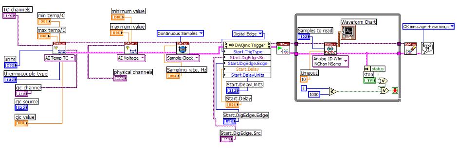
problems syncing multifunction with PCI-6229
Hi, I use PCI-6229 and LabVIEW 8.0 for synchronized of the thermocouples and voltage measurements. The diagram is attached here. Here are my questions:
(1) with the analog inputs of TC is ranked very first and followed with inputs analog voltage, as shown in the diagram, it works fine. But once the tension AIs are placed first and followed with AIs for thermocouples, thermocouple reading makes no sense, for example telling 25 deg C, the program shows strong fluctuating temperature 10-80 deg C.
(2) the delay time using DAQmx Trigger, here I put the Start.Delay = 2, Start.DelayUnits = ticks. And sampling rate = 1000 Hz for sample clock VI. Then, is equal to 2 X (1/1000 second) delay time = 2ms? If no deadline is set, which is the time between the trigger signal and actural reading? Will it be the time device resolution 50 ns?
All entries would be very appreciated.
Hi Matt11,
(1) the order that you specify strings in your task will affect the order of scanning. In other words, when you add the channels voltage before channels of temperature, the material can enjoy the tension or s channels followed by the string (s) temperature. Since the 6229 is multiplexed, it comes to each channel sequentially switching in a single ADC. In your case, it seems that the tension on the ADC to measure voltage not had time to resolve completely prior to taking the measure of temperature. We refer to this sometimes as ghosts in extreme cases where the value measured on channel b mimics the tension on the channel.
I think that you have found that you can get this by adding the TC task first. You could probably also get the same result by allowing more break-in between channels on your scan list. You can set the time between the channels with a Timing DAQmx property node (you can set the property is the clock frequency convert, which is the opposite of a waiting time). For slow sampling rates, sets DAQmx convert a default clock rate up to a minimum of 1/14 US (on the x 622). If your overall sample rate is less than 1/14 us (about 71 kHz) then you should have room to lower the clock rate to convert more of this if you wish to allow more time to settle between the channels.
I'm a little surprised that you see errors because of it (generally, the problem comes from a signal source of high imepdance measure or when sampling at higher rates), but then again, the temperature measurement would be very sensitive to small voltage fluctuations since you deal with thermocouple voltages at room temperature. Given the order of scanning affects your measure the problem is almost certainly introduced leaving not enough time for the ADC to settle after reading your string tension.
(2) ticks means actually timebase tick rather than the graduations to sample. The minimum is always 2, but this match 2 graduations of 20 MHz (100 ns) time base from which the sample clock (unless you choose otherwise or specify a sampling rate less than 20 MHz / 2 ^ 32), instead of 2 graduations of the 1 kHz sample clock (2 ms). In fact the trigger is probably performed asynchronously at the base of your time, if you are anywhere between the graduations of 1-2 the basis of delay time (50-100 ns) according to the relative phase of the trigger to the time base. If no time limit is set, the default value according to me is still 2 ticks which is the minimum that allows hardware (you can check on your own by reading the property node if you wish).
These points should be compatible between different driver versions, with the exception that DAQmx chose by default convert rate differently in earlier versions of 7.4. Select the conversion rate is a compromise between the settling of deadlines and the channels are sampled how "simultaneously" on the MULTIPLEXED Board. The final result in point 7.4 of DAQmx was a compromise apparently arbitrary add 10 US for the minimum conversion period and use this as the maximum by default between the channels. The user can of course always set the clock to convert to all what best fits their application (in your case, you might want to allow a settlement more between each channel).
Best regards
-
Data acquisition high speed (200 ksps / s) with pci-6224 or usb-6211 is possible?
Hello
I need assistance to complete a task.
The task:
Record a switch contacts twists every 5 microseconds (200 ksps / s). DAQ cards I have at my disposal at the present time are PCI-6224 and the USB-6211. The two cards are rated up to 250 kech. / s. I only watch 1 channel that will monitor the voltage.
Here are the settings I use:
CSR
Continuous samples
Sampling rate of 200 kech. / s
Analog DBL1 1 sam chan
timeout of 10 seconds (Read DAQmx)
The problem:
(1) every time I try to taste 200 kech. / s I get an error that reads
Measurements: Tried to read samples that are no longer available. The requested sample was already available, but has since been replaced.
Increase in the size of buffer, most frequently the reading of data or by specifying a fixed number of samples to read instead of reading all available samples would correct the problem.
(2) when you try to taste at a much slower pace of 50 kech. / s, the speed of the loop iteration is not realizing this speed setting.
My question is this: are these 2 cards (PCI-6224 or USB-6211) DAQ fast enough at my request and I do something wrong? OR
I use the wrong hardware to accomplish my task?
Thank you in advance,
Gerardo
The number of iterations has nothing to do with the number of samples if you do it right. You specify the rate and the number of samples you want and number of samples returned. You DO NOT loop 200,000 times. If you ask for 200 000 s/s and 200,000 samples, you will get this number of samples every second. It's really as simple as that.
-
Impossible to get CB-68LP play nicely with PCI-6229
Hi, I am using a PCI-6229 for 4 analog outputs (call them AO0 - AO3) and 4 inputs analog (call them AI0 - AI3), where I have 2 blocks of connection are the BNC-2110 and CB-68LP.
For now, they are wired like this:
1 BNC-2110 inserted in slot 0 (HAVE 0-15) of the PCI-6229
2 CB-68LP plugged into the connector 1 (HAVE 16-31) of the PCI-6229
The BNC-2110 things part works perfectly. I use it with success for all 4 of the analog inputs and 2 analog outputs. The connection was intuitively simple, by choosing the PCI-6229 s AO0 and AO1 channel assignments in the DAQ Assistant of LabVIEW and simply by plugging in my wiring in terminals AO0 and AO1 BNC to BNC-2110 connector block.
However, I can't understand how to wire the CB-68LP for analog output for AO2 and AO3 channels.
My basic, stripped stable approach to used the NOR Measurement & Automation Explorer:
-J' opened the dialog box indicating "Test panels: NI PCI-6229: 'Dev 1'.
-I click the "Analog output" section and choose from the drop-down list "Channel Name"
-J' I "Dev1/ao0" channels and "Dev1/ao1" working with terminals AO0 and AO1 BNC - 2110, respectively
- but can't figure out how to wire the CB-68LP to work with the 'Dev1/ao2' and ' Dev1/ao3' channels
I think at least part of my problem is that I can't find a pinout for the CB-68LP naming scheme.
Never mind, figured out that list of pins of the PCI-6229 22 and 55 on connector 1 match 22-55 CB-68LP screw terminals, allowing an AO2 (i.e. physical channel "Dev1/ao2"). Similar to AO3 idea. In retrospect, quite simple really
 problem solved.

Maybe you are looking for
-
Portege Z930 - a few questions after decommissioning of Win8 for Win7
HelloI recently bought Z930 PT234E with Win8 pre-installed. Due to the policy of the company, I needed this downgrade to Win7 Pro 32-Bit (deleted all partitions and creates a partition must usually be made). I downloaded all the drivers for the OS an
-
This software works well with Mac to convert EPS files in JPEG files?
This software works well with Mac to convert EPS files in JPEG files?
-
Why my PC cuts her Internet connection whenever I try to open a PDF file and how can I fix the problem? Even if I still have my cell phone internet access will not open a PDF document online.
-
Track numbering on MicroSD card
My rocket is playing tracks in the wrong order in Album mode. But this problem is present only for the tracks on my microSD, not those of the main memory. When I go to the file information, it shows a weird number for the track #. For example, Nine I
-
HP Pavilion dv7-6015tx Windows Edition home premium x 64 My problem is that my usb 3.0 ports do not work the only time where I can make them work is to power off at the wall for 5 minutes, but if I restart the pc after cela or even let him go to slee