atan2 in FPGA of point sets
I use the function atan2(x,y) implemented on a FPGA (OR-7851R) and have a simple question that frustrates me.
See the attached vi, my two inputs (x, y) are fixed numbers in decimal, length of 16-bit words, 1 whole bit (this is to say, - 1.000000, 0.9999695 with 3.051758e - 5 precision).
Since atan2 must be a value between - pi and pi and labview outings pi radians (and not simple radians), I would expect the output to be the same format as the input, a 16-bit number between - 1 and 0.9999695 (3.051758e - precision 5) with 1 single bit used to the whole.
Instead, the VI requires to be a word of 16 bits, but with the whole part of 2 bits (that is to say, - 2.0000, 1.999939 with 6.1036e - 5 precision, see attached photo atan2_output_type.png). This earns me nothing and I have only half the accuracy I should have! I tried several entries and I confirmed it returns only numbers between-1 and 0.9999389 (6.1036e - 5 precision).
I can't seem to be able to change it because all the options in the dialog box are grayed out (see attached photo atan2_dialogue.png), as he decided that's what he must return in light of my entries. Can someone explain why it does this? Is there something simple that I'm missing? I need that little extra to go on decimals, not the whole of my fixed point number side.
Thank you
Dan
Hi Dan,.
Normally, a little like that growth is due to a case of corner, I guess in this case it takes cover 1.0 pi radians as an output as possible. If you need more precise output, just to increase the word length; with a fixed whole word length, all the bits that you add will be fractions. If you don't want the whole extra bit, just throw it away using fixed point to set the length of whole word to 1 and the overflow mode to Wrap.
Jim
Tags: NI Software
Similar Questions
-
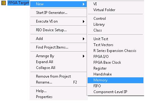
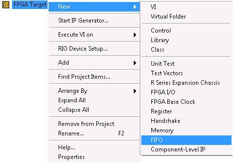
Element memory FPGA vs point FIFO
What is the difference between the use of a FPGA memory element (
) and an element of FIFO of FPGA (
)?
I am looking to unload data so quickly that possible between a host application and a target FPGA VI, but these two options seem to be sometimes used in the LabVIEW help documents and white papers. I understand the DMA from the computer point of view works and I would use this approach because it is the fastest (I need a very fast data acquisition system).
No one knows what what are the specific difference between these, and (especially), which will be quicker for entire U8 transfer data?
They are both created by click with the right button on the FPGA target:
Thanks in advance for any help!

To transfer data from the FPGA to the host, a FIFO DMA is your only option. Blocks are only to transfer data between the loops in the FPGA. A part of memory is not shared between the host and the FPGA.
A FIFO DMA is implemented by memory allocation on the FPGA and the facilitator. The DMA logic automatically moves data between them, but there are two distinct categories of memory, one on the host and the other on the FPGA.
For communication between the loops on the FPGA (without involving the host), the most important difference is a FIFO, as its name suggests, first-in-first-out, while a block of memory is addressable. There are also differences in how they can be used to transfer data between the different areas of the clock loops, as described in the help. If you have a question about a specific help section, please quote or link to the part you find confusing.
-
access the definitions of point-set up
for some reason, I just can "t type in my head around manual definitions.
I would like to implement one of these things for my wireless router. It lights up in a remote area of the wireless router and plug in a laptop or a pc that does not have wireless capability. I understand the real con - fig (wep ssid), just not what structure to use. ad-hoc, infrastructure?
out on the terrace
receive the wireless signal
connect on wireless or portable pc and be connected
ver 2.8 wap11 access point
If you want to use the WAP11 as a client device on a PC that doesn't currently have a wireless capability.
Mode Client AP is the way to go.
Preconfigure the WAP11 depending on your network.
The value thwe default gateway IP address of your router.
Set the WAP11 to AP Client mode and do a study site for you sure have the right MAC address of your router.
Concerning
Fred
-
How can I assign partial credit so that for each possible answer 6 out of 10 each correct answer gets 10 points each, with a possible total score of 60 points quiz?
To Captivate 7, please go to the Quizzing workspace. You will have the properties and properties Quiz Panel visible. I will now repeat the workflow, I explained briefly for CP7:
- Check the partial score in the Quiz properties and also multiple responses.
- Indicate the correct answers on the stage
- Select the first correct answer on the stage text caption and indicate its score (10pts) in the properties panel, not in the Quiz properties!
- Repeat the same for each correct answer
- Check the total score in the properties of the Quiz Panel: should now be 60pts to the full question.
None of the quiz system variables can be changed, they are read-only. System variables in Captivate 6 - Captivate blog explains the system variables for 6 categories, there are a few changes in 7: new features of Captivate 7.01 - Captivate blog but the Quiz category is always read-only.
-
Point Set size dynamically the value of the corresponding select list
Hi friends,
Few days, before I learned a concept of change the size of the item dynamically according to the value of the selection using Jari list. I missed to ask him something (such as an extension of it).
This is the thread
{: identifier of the thread = 2282838}
He produced the wonderful example below
http://actionet.homelinux.net/htmldb/f?p=100:214:7956651650754287:NO:_
Was that I missed in it, it possible to change the label of the element according to the selection list.
According to the example, jari has limited the size of the element according to the selection list. Suppose that in this example if I select "China", im getting elements of different size and "India" means im get point of different size. But the labels of all the four elements are the same as
attribute < li > 1
attribute < li > 2
attribute < li > 3
attribute < li > 4
As an extension, I need like assume that 'China' means that the label of the columns must be
< Li > State
< li > address
< li > pincode
< li > district
If "India" is the label of the four elements must be
< li > customers
< Li > operators
< li > units
< li > provinces
It is possible to generate different labels for the different size points, according to the value of the selection list. Since there are only four elements present in the database table.
Brgds,
MiniHello
Alter the table where you have point sizes and add the ITEM_LABEL column.
Fill the column with the values you need for labels.
Add the new column for the application processDECLARE l_sql VARCHAR2(32700); BEGIN l_sql := ' SELECT item_name, item_size, item_label FROM demo_item_dyn_size WHERE lov_value = :P214_COUNTRY' ; APEX_UTIL.JSON_FROM_SQL(l_sql); EXCEPTION WHEN OTHERS THEN HTP.PRN('{"row":[]}'); END ;And change something like JavaScript
See working example
http://ActioNet.homelinux.NET/HTMLDB/lspdemo?p=214Kind regards
JariPublished by: jarola on 27 Sep 2011 19:39
Corrected JavaScript.
-
Point set Label above point on the form?
My apologies if this has been listed here. I could not find with the research I've done.
In my data entry form, I want to put the labels of items entrable top of the fields. I looked at the label (optionally with help) model, but it looks like that just the label itself handles. I don't see a way to get to the #BODY # of the region (region without buttons or title) do it either.
Are we stuck with having always our labels in column to the left of the items in a form?
I hope not and knowing a minimum necessary?
Thank you
StewFor the element, set Begin on the new line = YES and start the new field = Yes
Then to the label set "Horizonal/Vertical Alignment" 'at the top'.
(It's in v4.0.1.)
-
Point SET value with button redirect url
Hi guys!
I wonder how to value of the element with a value of another article
I use this:
JavaScript:popUp2('f?p=101:2:&session.:::P2_TEST:&P100_SEL_RECORD_LIST.',400,300)
but it't does not not ;/
With respect,
PsmakRJavaScript:popUp2 ('f? p = 101:2:'+ $v ('pInstance') +': P2_TEST:'+ Escape ($v ('P100_SEL_RECORD_LIST')) + ', 400, 300')
You can avoid the app_id hardcode too (if it's the same application) using
JavaScript:popUp2 ('f? p ='+ $v ('pFlowId') +': 2:'+ $v ('pInstance') +': P2_TEST:'+ Escape ($v ('P100_SEL_RECORD_LIST')) + ', 400, 300')
Use JS function to escape special characters in the URL string
-
Comparison of matrix FPGA by element wierdness
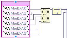
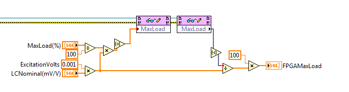
I have an application where I am comparing limits to the input values of two strain (OR-9237) inside an FPGA cards making a conditioning of signals for a subsystem in a larger machine.
Process boundaries are sent to RT as a table and compared to a table of "raw" data entry
Data entry-
Comparison of limit-
I do one per element to the "GOLDEN table" and I realize that this may or may not be more effiecient as a comparison aggregates; However, the strange thing that happens is that the sixth element of the array to limit triggers a "load error" for the fifth element of the input array.
I send you the limit directly from the RT - PS
Note that the verified calculation by reading the value defined in the FPGA. This set and get here seem to line up. That is to say, if you set the element 3 MaxLoad % or LCNominal(mV/V), it is validated on the FPGAMaxLoad output. I wonder if this has anything to do with the implicit conversion between floating-point single point-to-point fixed?
If someone has had this experience, I would be grateful feedback on what is happening.
I really want to engage in the DMA channel as it is a very small set of six elements that one, it seems more kill to use a DMA channel just for this operation.
Thank you
Drew
-
You try to run the scan mode and mode interface fpga at the same time is causing errors
I'm reading a 9236 9237 and a 9215 with the scanning engine and read from two 9211 modules with the fpga. It's because I need to acquire to 200 Hz with the 9236 9237 9215 but maximum rate of the scan engine is limited by the slower module in the system, which in this case is the max of 15 hz the 9211.
So to use both interfaces (scan engine and fpga), I followed the percisely given in this article for instructions.
1. the project has created and added the peripheral crio using the interface of the scan engine.
2. Add the target fpga and drag and drop the 9211 inside modules
3. has created the fpga in interface file with and compiled with no error.
4. interfaced with the file fpga at almost exactly the way the sample project of "getting started with 9211' by using the engine of analysis in the interface with the other modules.
5. after the errors to discover that I created a VI that tests for just the portion 9211 code (called "thermocouple FPGA method Test.vi")
The data returned by the interface fpga was nothing else than zeros on all channels, even if thermocouples were hooked on some of them. (all zeros as entries in the convert temperature vi gives-410, 6160 degrees F, if you happen to have the material to try this.)
I get the following error from the open fpga vi reference:
code error-61141
"Thermocouple method Test.vi FPGA.
Activities FPGA:Open FPGA interface reference.
Reserved outside LabVIEW FPGA: turns The RIO Scan Interface. You must set the mode Interface FPGA chassis in order to unlock the FPGA. »It's extremely frustrating, because as I explained, I've been very attentive not only follow the instructions for concurrent fpga and analysis but also to model my VI by the example of VI, even if only for the moment, just to try to work things out.
Any help would be appreciated as I need to fix this for the further development and I am somehow in a lack of time. I opened a support ticket (reference #7256226), but the app engineer had no time to answer.
My system:
cRIO-9014 controller RT with crio-9104 bottom of basket.
LabVIEW 2009
Latest drivers and peripheral software pc and rio (RIO scan 3.2 engine support june2009)
rex1030 wrote:
I'm reading a 9236 9237 and a 9215 with the scanning engine and read from two 9211 modules with the fpga. It's because I need to acquire to 200 Hz with the 9236 9237 9215 but maximum rate of the scan engine is limited by the slower module in the system, which in this case is the max of 15 hz the 9211.
This should not be the case. 9211 data will not update with each sweep, but you should be able to run the scan faster than 15 Hz without problem. Do you have specific issues with this?
So to use both interfaces (scan engine and fpga), I followed the percisely given in this article for instructions.
1. the project has created and added the peripheral crio using the interface of the scan engine.
2. Add the target fpga and drag and drop the 9211 inside modules
3. has created the fpga in interface file with and compiled with no error.
4. interfaced with the file fpga at almost exactly the way the sample project of "getting started with 9211' by using the engine of analysis in the interface with the other modules.
5. after the errors to discover that I created a VI that tests for just the portion 9211 code (called "thermocouple FPGA method Test.vi")
You can try making sure that the chassis is set to mode Interface FPGA and the setting is deployed. I wrote that article that you referenced says will select the deploy option later and not explicitly speak to deploy the chassis later. Run a VI with a reference open FPGA vi not automatically deploy chassis settings if you need to do it explicitly. Try the following steps.
1. right click on the frame element and select Properties. Make sure that the Interface FPGA option button is selected. \
2. right click on the frame element and select deploy.
3. repeat your VI.
The data returned by the interface fpga was nothing else than zeros on all channels, even if thermocouples were hooked on some of them. (all zeros as entries in the convert temperature vi gives-410, 6160 degrees F, if you happen to have the material to try this.)
I get the following error from the open fpga vi reference:
code error-61141
"Thermocouple method Test.vi FPGA.
Activities FPGA:Open FPGA interface reference.
Reserved for LabVIEW FPGA outside: The RIO Scan Interface is running. You must set the mode Interface FPGA chassis in order to unlock the FPGA. »The likely cause of this error is that the setting of the FPGA Interface on the chassis has not been deployed. If the chassis is still Mode Scan fixed personality bitfile will be loaded on startup and the FPGA will be locked.
It's extremely frustrating, because as I explained, I've been very attentive not only follow the instructions for concurrent fpga and analysis but also to model my VI by the example of VI, even if only for the moment, just to try to work things out.
I'm sorry that you have had difficulties. Assuming that I'm wrong about the source of your problem, it seems we have to update less than Ko to include the deployment step.
Any help would be appreciated as I need to fix this for the further development and I am somehow in a lack of time. I opened a support ticket (reference #7256226), but the app engineer had no time to answer.
My system:
cRIO-9014 controller RT with crio-9104 bottom of basket.
LabVIEW 2009
Latest drivers and peripheral software pc and rio (RIO scan 3.2 engine support june2009)
-
Several loops of RT; A single FPGA reference
I have three loops using the same reference FPGA.
Loop 1 - reads most of the data in the FPGA for display on the HMI
Loop 2 - using the information made available to the loop 1 as well as some additional data that is read from the FPGA to perform the functions required by the HMI controls and writes for the FPGA.
Loop 3 - uses data from Loop1 as well as additional data read the FPGA to run commands fuctions and wrote security for the FPGA.
My questions are:
The FPGA Refence points to a single memory block where all three loops are looking at the same data?
I need on While loops shift registers to keep data updated correctly?
I need to run the three sons reference FPGA close While loops to close the reference correctly?
Yes. N ° N °
I assume you mean wire reference FPGA entering a node that reads the FPGA reference you speak or write in the Panel control or indicator that is part of the VI running on FPGA.
-
FPGA - try to use the screw of the replication of RIO to replace going to reset the FPGA running
Running LabVIEW 12.1
We have an application that uses an FPGA that was compiled in Run to Reset (works on any reset or power on). Sometimes we need to update the image on the RT and FPGA and I downloaded the NI RIO replication screw.
The problem I have now is that when I got to download the bitfile on the Flash FPGA on the sbRIO9636, I get the following error:
Error-61141
Possible reasons:
LabVIEW FPGA: The operation could not be performed because the FPGA is busy. Stop all activity on the FPGA before asking this operation. If the target is in the Interface of Scan program mode, put in FPGA Interface programming mode.
My updater is stand alone EXE. He isn't able to get a link to the FPGA, because we are not sure what Bitfile currently is on a particular system. I tried using the open FPGA reference and load a VACUUM on the FPGA bitfile by setting the FPGA to RUN when he sound the FPGA VI of the Open reference - and it works for me to erase the bitfile. It does not allow me to immediately after run the bitfile VI of replication of RIO download - even if I close and reset the FPGA before trying to download the Bitfile for the RIO Flash.
I have to first delete the existing bitfile, then load a new?
Well, I found what I consider as a workaround - but maybe it's required to do things - but it doesn't seem like it should be, since the RIO device Setup.exe is able to flash or clear the bitfile regardless of the State of the FPGA.
What I've done is to define the FPGA to "do not load automatically on re" then call the RT Config screw system and order a restart of the system. The RT operating system restarts and then restarts the RIO system and this ensures that the FPGA is not busy. Then I'm able to erase them or write about a new bitfile for the RIO Flash and set the "Automatic loading on any Reset" Rio de JANEIRO and restart the system again.
Our current situation, it will work. Long time restarts do a bit of headache.
-
GetCommand does not return my configuration of entry points?
If I'm in a file of sequence of customer and I want to run dynamically my own configuration entry point in the process model which is the best way to do this?
I try to get the application manager through a step of the activex using Engine.GetInternalOption (InternalOption_ApplicationmManager), and then I choose the GetCommand with CommandKind_ConfigurationEntryPoints_Set method. It will use only a clue to one of the entry points setting 3 by default (report, model Options, or Options of database Options). If I try to make my own, it throws an index out of range. It's position to James Grey here: http://forums.ni.com/t5/NI-TestStand/Calling-a-Configuration-Entry-Point-from-a-C-code-module/td-p/1... (I'm not in .NET well. I just want to use activex steps in TS). The default 3 those who work perfectly. It's only when I try my own that I added.
Any thoughts?
When you run again you do execution of process template or a direct call to the sequence? If you make an execution of process model with a sequence of the client file and the specified model, it must call reminders. I don't know why the case of app Manager you try does not work. Maybe someone else can help with that. I wanted to just suggest the new approach of the execution because it looks simpler.
-
synchronization sequence FPGA structure problem
Hello
I use a sequence structure in a VI on the FPGA to a cRIO-9073. The time of each sequence is active is determined the number of times defined by the user. In theory, each sequence should take the same amount of time, but when I check it with an oscilloscope is not the case. The signals produced do not have the same cycle. When the number of ticks is equal to 1 in the VI on the FPGA, I receive a frequency of 400 Hz, approximately to the blockwaves outputs. I expect it is much higher since the FPGA runs at a frequency of 40 MHz clock. Why the frequency of the signals so low and why isn't the market factor the same for all signals?
Best regards
Beurms Jasper
Several of your synchronization on the FPGA screws are set in milliseconds, not ticks; in all cases but cases #2. I hope that this is the problem. Double-click the VI and change the setting. In fact, why have a timer to wait in any case? Just pull it outside the structure of the case and have 1 instance of the VI in the while loop. Also, whenever I see the files named * _
it probably means that you do not use the source code control. I would highly recommend. -
Hello. My name is Jason. I'm working on what should be a very simple project to form a collaborator on the material OR that we work.
I used this equipment in the past to remotely control a ranger xp. I tried to use the exact configuration of the code... I'm not sure what I did wrong.
Screenshots of the Project Explorer, and the screw runs on the PC, the cRIO FPGA have all set up and.
The goal
I want to be able to Flash an LED using the crio and control the speed of the flashing of a VI running on my PC. The VI running on the PC has a slide to control the speed of blinking and a Boolean switch to activate and deactivate. The VI on the cRIO multiply the speed by two and shows the State of the Boolean switch. These values are passed to the FPGA VI which is supposed to turn off the led market and stop.
The problem
The PC code and cRIO seem to do exactly what I want to do. Digital i/o does not value. There is no error coming out blocks of reference or FPGA read/write.
I didn't know where to post this because I can't see the error is coming from. The only error I have found is when I right click on the program, I wrote and respected to run on the fpga and try to download it. This error - 50001 and causes "an attribute whether explicit or implied is not relevant or is not relevant given the current state of the system. The operation could not be performed as indicated. »
The system hardware
I have a PC running Labview 8.2 (ip or subnet address 192.168.0.70 255.255.255.0) it is connected with a cable crossed to a cRIO 9004 (address ip 192.168.0.2 255.255.255.0 sn) and a cRIO-9104 chassis. The cRIO has a digital I/o module (NI 9401).
Software
LabView 8.20
Module FPGA 8.2.0
Module time real 8.20
any help/advice/tips would be greatly appreciated.
Thank you
JAson
Hi jcoates,
Please take a look at this knowledge base article: Why do I get error 50003 when you run an FPGA VI on my real-time controller?
If this does not resolve the problem, you are able to get a simple FPGA VI, which does not interact with the LED work?
-
How to control the speed of the pointer mouse on the login screen?
How can I control the speed of the pointer mouse on the login screen?
I put the speed of the pointer in a way at once two users accounts.
I think that when I go to the login screen by using change user, the speed of the mouse pointer is the same as the user configured the pointer speed. (I suspect it's the speed of the pointer to the user account that I'm spending.) TO BE DETERMINED. "But it doesn't matter, because they are the same).
However, when I go to login screen using Log Off, the mouse whips autour at a very fast speed - much faster that the speed of the pointer set up users.
[EDIT] It is also the speed of the mouse when you go to the login screen after you start the computer.
It is disconcerting to the 87-year-old who uses the computer. (Read: barely in computer science.)
FYI, I don't have not noticed this until I went from a wired mouse to Dell for a Logitech wireless mouse. (I have turned to bike computer.)
Also, users configured users pointer speed is the 2nd from left to right, with improved set the pointer precision.
I wrote:
However, when I go to login screen using Log Off, the mouse whips autour at a very fast speed - much faster that the speed of the pointer set up users.
[EDIT] It is also the speed of the mouse when you go to the login screen after you start the computer.
By examining the registry, I found that MouseSensitivity is set to 2 for two HKEY * users, but it has been set at 10 for the other four.
The problem was solved by putting others 01:56 institutions.
I have this will mark as answer unless someone offers a better solution soon, ideally one that doesn't require editing the registry.

Maybe you are looking for
-
Hello Skype community. So I want to get a new Skype account with the user name "-", but whenever I click on the button "Registration" on the homepage it redirects me to join through live.com, which will make my username have the "live: ' tag inside.
-
Will this work with my HP a1550y?
Will this work with my HP a1550y?
-
What is the command of shortcut for all windows get the information from the computer?
What is the command of shortcut for all windows get the information from the computer? instead of going to the computer / my computer > properties > discover the pc... basic information or go to the control panel... just a command for windows xp, vis
-
I got a disabled system 80778715
-
Routers using broadband as simple access points?
I need a simple Access Point and the WAP610N seems sufficient. However, I would like to get capacity simultaneous dula-band, and it seems that I have to go to something like the WRT400N to get the. However, the WRT400N has a broadband connection. I c