attachedObject inside a signal?
Hello!
Is it possible to check (/call?) a signal inside the attachedObject materials, for example within a checkbox component?
Checkbox {}
attachedObjects:]
{SystemToast}
onCheckedChanged: {...}
}
]
}
Thank you!
Partial REPLY & EDIT *.
Do not nest like that. Simply call toastID.show () of the signal that you wanted him associate.
Ask again how best to put the logic inside a toast of system. For example, to say one thing, if the box is checked, another if it is not checked.
Hello
Of course, you can enjoy the SIGNAL and SLOT mechanism.
onCheckedChanged: {...} is a predefined for signal checkedChanged Manager.
You can connect checkedChanged to your own function.
Here the code for you, try this
import bb.cascades 1.0
import bb.system 1.0

Page {
    Container {
        CheckBox {
            id: checkBox
            text: "check me"

            onCreationCompleted: {
                checkedChanged.connect(myToast.onCheckHandler);
            }

            attachedObjects: [
                SystemToast {
                    id: myToast
                    body: "So long! Thanks for coming, see you next time!"

                    function onCheckHandler(checked) {
                        body = "Item checked : " + checked;
                        show();
                    }
                }
            ]
        }
    }
}
Tags: BlackBerry Developers
Similar Questions
-
There is no such thing as PushService createChannelCompleted signal
Dear BlackBerry developers
I am building an active push application. So I started with the PushService class to create a session and a channel and other things. Because I need the token server gives to my application, I need to connect with the createChannelCompleted (const bb::network:
 ushStatus status, const QString & token) signal. This signal is copy pasted from the documentation on here http://developer.blackberry.com/cascades/reference/bb__network__pushservice.html.
But I always get the following error message
Object::connect: No such signal PushManager::createChannelCompleted
I tried all the ways to connect with the signal
connect(pushService, SIGNAL(createChannelCompleted(const bb::network::PushStatus&, const QString&)), this, SIGNAL(createChannelCompleted(const PushStatus&, const QString&)));
But I can't get it right, apparently.
Thanks in advance!
Hello
This should work:
QObject::connect(service, SIGNAL(createChannelCompleted(bb::network::PushStatus,QString)),
                     this, SLOT(onCreateChannelCompleted(bb::network::PushStatus,QString)));
Statement of slot: / / upd: fixed a statement of slot
void onCreateChannelCompleted(const bb::network::PushStatus &status, const QString &token);
Your statement should probably also work if you replace second SIGNAL() SLOT() and use a full PushStatus in the slot. But for const const reference and & can be left inside the SIGNAL() and SLOT() statements. MOC will remove them automatically anyway.
-
I hope this isn't a stupid question:
I am trying to catch the signals of some containers of touch, touchEnter and touchExit.
I have:
Sample class: {public QObject
Q_OBJECT
public:
Example();
virtual ~ Example();signals:
...
public slots:
void touch (bb::cascades:TouchEvent * event);
private:
...
};
I'm trying to connect the touch of the container to my contact:
Boolean result = connect (example_container, SIGNAL (touch(TouchEvent*)), this, SLOT (touch(TouchEvent*)));
Q_ASSERT (result);But he said that neither example_container, nor this ' touch is a signal/slot. I get the docs:
Looks like a slot for me not to mention that mine is in the locations of the header section.
No idea what I'm doing wrong here?
Hello
Inside macros SIGNAL() and SLOT() type names should be complete. MOC cannot resolve the namespaces.And just to be sure, I suggest using a different name for the housing, e.g. onTouch. It is not mandatory, but avoids conflicts if you represent a signal with that name or inherit from a class where the signal is reported.
Boolean result = QObject:connect (container, SIGNAL (touch(bb::cascades::TouchEvent*)), this, SLOT (onTouch(bb::cascades::TouchEvent*)));
public slots:
Sub onTouch (bb::cascades:TouchEvent * event);
-
niUSRP Signal.vi set not allowed inside loops?
It seems that niUSRP than signal.VI set is not allowed in loops. After the decision of the VI, I get this message:
niUSRP configure Signal.vi
, this attribute cannot be changed while the driver is in the operating state. Is there a way to change the frequency of the carrier, while the driver is running? With the help of property Node.vi of niUSRP to set a new frequency within a loop is also not working. My goal is to create with the USRP to frequency hopping.
Hi YYY.
Thanks for your VI, including in the post. I was able to download it and reproduce what you see. There are a few things that need to be changed in order to get this to work.
First of all, you don't need to have the niUSRP function to configure Signal.vi inside your time loop. You can put this outside the loop and a property node allows you to change the frequency with a property node. You already have the property node in your code, you just need to change it to write instead of read. There is an example that will do just that, if you just want to use it instead of modify your code too much. It's called niUSRP EX Tx continuous Async Reconfig on the Fly.vi.
Then, the reason why you are not able to go at the rate of 1 ms/s IQ with the code you have is because you're trying to read and write the frequency during each iteration of the loop. Because of the time to query the hardware, set the frequency and read the return frequency, the I was able to get the maximum rate of IQ was around 500kS/s. This is due to a combination of hardware and driver limitations. Even with the example above uses the property instead of the function of the configuration node, if I put in an indicator to look at frequency I can't use a faster speed of the IQ.
Try to change the property node and the withdrawal of this indicator, you should have a lot more success. Let me know if this does not work for you or if you have any other questions, I'd be happy to help you.
-
How can I extract a part of a signal inside a loop control and simulation?
I would like to extract the part of my signal between 0 and 3 seconds. I tried to use the extract of Portion of Signal VI Express, but it does not work. I'm setting the length to the offset 0 and 3 seconds. However, nothing is displayed in the output. I used this before VI successfully, but it wasn't in a loop control and simulation. Is there something special I need to do to make this work properly in this case?
This forum shows how to measure the time between the Digital pulse http://forums.ni.com/t5/LabVIEW/Measuring-time-between-digital-pulses/td-p/1056881
In addition, it would be a good link https://decibel.ni.com/content/docs/DOC-12160
-
Hi all
My HP Pavilion Elite HPE series desktop computer product # #ABU, model # HPE XS622EA - 590uk is no longer gives a reliable result to my monitor.
I performed a system restore and then updated to Windows 7 Ultimate from Home Premium in an effort to solve the problem without a bit of luck at each setting.
I tried two HDMI cables that both use to work between the office and the monitor, the cables still work and of fact so the monitor, I used the HDMI and the monitor cable and connected to my laptop Presario CQ61 to confirm, I also tried using DVI cables with the same results without success.
On this basis, I believe that the problem is a hardware inside my office, I'll check for any failure, loose or broken connections/electronic cards.
When the problem occurred firstly I could connect the monitor with a PC cable and pc adapter DVI, the office was more no shortcuts or a menu bar, where the reason I did a system restore, after restoring the system, I was able to use the HDMI cable but the signal on the screen is quickly become intermittent and then nothing It was the same status with the DVI cable, and it was common to the two HDMI and two DVI outputs.
Just to confirm, that I didn't have problems with the operating system feature, everything starts up fine and I can access all the user accounts, as long as I can see

Anyone had a similar experience or any idea what parts I should check for this problem.
Regards and thanks in advance for any help
Lee
The first thing that comes to mind for me is the video/smart card. You have a card or you use an onboard video chip? If you have a video card, check if you have a fan which may not be spinning. This chips overheat and cause a failure. You should also look carefully at the video card and check for capacitors that are bulged/rounded. I would also check for do not have capacitors on the motherboard as well.
-
I BOUGHT THE BIKE MAY 22 G. AFTER ONLY A WEEK, I ENCOUNTERED PROBLEMS OF SIGNAL IN MY DEVICE.IT WENT TO EMERGENCY CALLS ONLY MODE WITH A TRIANGLE GIVEN SIGN MORE RED ON THE INSIDE.
I RESTARTED THE PHONE AND THEN AFTER 1 MINUTE SIGNAL CAME. AFTER THAT, ACCORDING TO THE SUGGESTION OF THE TECHNIQUE OF FLIPCART TEAM I HAVE RESET FACTORY DATA. THEN THE PROBLEM CAME ONCE FOR A FEW SECOND, BUT AFTER A DAY AND NOW UNTIL THE SECOND DAY HIS JOB VERY WELL.
PLS SUGGEST WHAT TO DO IN THIS CASE.
IS MY PHONE IMEI NO. - 355004054071637
ID E-MAIL - [email protected]
Closing thread now to comments reducing clutter
-
Why is the signal to my airport express base station weaker?
My airport express base station to base station (part number MC414LL/A) has worked well for the first 3 years, but now has a weaker signal is no longer covers the apartment. The location has not changed and we have not added all of the devices that could create interference.
Any help would be appreciated.
Bill
3 years... average... is on when the internal of food inside the Express starts slowly the head downhill, so maybe it's a factor here.
If you don't have already done, power off the AirPort Express for a few seconds, then put it to the top. When you start the Express, it will automatically scan all channels use wireless sector and select the best channel to use both. If you live in a crowded environment, you may have to restart the AirPort Express on a regular basis.
If there is no improvement after a few reboots of the Express, on what you can do at this point is to reset the device back to the default settings and then set up again to see if a new beginning offers some improvements in the intensity of the signal.
-
Jitter in response to signal generator of digital dashboard by using trigger nor tclk with digitizer
I've written a VI that uses NEITHER tclk to synchronize a generator (PXI-5422 named FGEN1) and a digitizer (PXI-5122 named DIGITIZER1). There is also a clock card TIMING3 generating a digital camera.
It seems that can probably be explained by the way TCLK to synchronize, but I don't understand all the details. Could someone help explain this to me?
You are right. NOR-TClk ensures that all synchronized devices start at almost at the same time, to the same sample clock, with timing very tight. Sometimes, the level of synchronization with the devices OR TClk-synchronized beats at the level of the synchronization of the instruments of some competitor channels in the same device. But this is not free, there are compromises and added additional jitter for trigger response time is one of them. Here is an attempt to explain why:
When you use NEITHER-TClk and send a trigger, the devices will respond to relax on the next cycle of the clock once made the trigger signal to the device. Let's say you have several devices all of them even configured with the same clock frequency. You block the signal of PXI_Clk10 using their PLL, so they drift out. But each unit's clock edge will be off, clock +-0.5 cycles. If you send a trigger to each of them, they will respond on the next clock cycle whenever it is, after the arrival of the relaxation to each device with different propagation times, whatever they may be. You get a single clock cycle of jitter on reaction of device to set it off.
When you use NEITHER-TClk, several things happen: all devices are locked on the PXI_Clk10 signal to eliminate drift. The device clocks are then adjusted to a period level secondary clock. Very very tight. Then a clock signal common, slower called TClk is produced inside the devices. All the generation of trigger are delayed to be sent to the next rising edge TClk, and all consumption trigger is delayed to be received at the next front descending TClk. This way you make sure that propagation delays don't mean one of the devices does not react to the trigger until the next clock cycle.
That's why you see jitter above the reaction time of relaxation. When you add devices with different clock settings, so the frequency of the TClk can be slower for a divisible frequency in the device clock frequencies everything is possible. This causes the trigger jitter of reaction time be even slower!
I hope this helps you understand what you see.
-
I use a signal splitter in the given file. It separates the signal into six parts. I use a waveform chart to show the signals. But the only exit from split is shown on the chart... Five others are missing... Why... ? How can I get six waveforms on the output... ??
As far as I know none of the screws on the standard pallets provide no direct way to create a three-phase signal. Six sources, all with the same frequency and different phases and amplitudes, is a simple way to do it. Alternatively, you can create a table of the phases and amplitudes and thread in a loop with the signal source VI inside the loop.
I'm not a fan of the Express VIs for this kind of things. First, they have the flexibility to run the lower floor screws on the range of Signal Processing. The Type of dynamic data hides the data structure he wears. According to what will be done with the data later, I prefer the waveform data type or simple tables. And the huge icons occupy too much area of block diagram.
Note that the use of tables as in this example change the x-axis in the charts. The units are clues of paintings, the equivalent of 1 sample per second.
Lynn
-
Incorrect behavior when using the sliders on a signal enlarged
I started recently by using sliders to determine specific values in a recorded signal.
Problem is when I use the Zoom tool (the magnifying glass under the time scale icon inside) to zoom in on a specific peak dysfunction of sliders. When you take a slider handle and drag the intersection of cursor is no longer follows the track of the signal in the graph.
To recreate:
- Log data with Signal Express seconds. I always pass the signal by the amplitude and levels step to display the signal as a graphic of the scope.
- Right-click on the graph and select visible items > sliders to add the sliders to the chart
- Use the handles to slide to move the cursor cross along the signal.
- Click the magnifying glass in the time scale, and then select the Zoom (top left of the box that is displayed)
- Click and drag on the chart to zoom in on a signal peak.
- Now use the grab handle sliders intersect on the zoomed pic in.
- Cursors follow the path of the signal.
I'm pretty confident that it's recreateable, because the same behavior exists on both machines in the lab as well as the software in beta 2011 at my office.
Rory,
Thank you for your patience during the attempt to isolate this problem. I'm glad that you could see up to a kind of stange behavior.
You describe exactly what I see on my end. If you zoom in far enough the sliders 'think' it follows the signal when in fact it's a ghost left by an already enlarged resolution signal.
The solution is to change the graphic for graphic band momentarily while I use the sliders, and then back again to view the actual data.
This isn't really a drawback, but I'm happy that we can document as a bug.
Thank you!
-
create the pwm with mcc usb signal 2408
Hi all
I want to generate a square wave of PWM adjustable frequency and factor market out of my usb usb MCC 2408-2ao module.
I know thatI could use while loop with a sequence of plate inside to put on and off of a digital output on an ongoing basis and by changing the duration the sequence of flat images and the time between one and another iteration of the while loop I can vary heavy duty and often... but it seems a little tedious to do.
Is there an automatic way to generate a PWM signal to measure and send it to the output of the USB module in Labview?
Thanks for all your help!
-
frequency of measurement of digital random signal
Hi all.
I want to measure the frequency of the signal. This value will be sent to any other device to vibrate the vibrator according to the value.
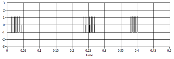
For example, I want to measure this signal:
I try to use your vi and extract single signal measure vi, but the result is not fair, for example, if I have no pulse on the graph the result is 11, 5 Hz (it should be 0 Hz)
I use assistant NI USB-6210 and acquisition of data to get the data from the sensor
Laughing out loud! All that motivates you... I don't see attachment. I commented on the block diagram on the vi attached which may help. What you can do in your data acquisition program, use is get the queue with the name of data. Then take the waveform of the DAQ assistant and use waveform components get to retrieve the values of the real signal (-1 to 1). Now use a loop with automatic indexing on table of signal and inside use enqueue to place each value of the signal on the data queue. In the joint programme filter, you can either copy the lower node in your program for the acquisition of data, or remove the loop of high signal generation and run them in parallel. The nice thing about the queues is that they can transport data between different vi on the same computer that the name is the same. If you want to do something with the frequency measures, while you can use a different queue for buffering of the data out of the loop of measure.
Good luck!
-
The output of a PXI6602 signal is adjustable to continue once completed the vi?
I have a PXI6602 that I use to simulate a quadrature encoder signal, but the signal must be present for any longer that the vi is open.
The signal is possible to continue after the end of the vi while I can interogate the unit of the signal goes in and then stop the signal with an another vi once I finished?
David.
Thank you, James.
to solve the problem, I created a sub vi for the questioning of the unit and put it inside the vi creating the signal so that once the signal is present the unit data are recovered then the DAQmx responsible are arrested and cleared.
Kind regards
David.
-
Programmatically formatting graphic mixed signals
I am writing an FPGA application where I am acquiring data from a unit under test (USE). The PXI-7842R digitizes 3 groups of signals:
1. an analog voltage monitor
2. 5 digital signals connected to the analog inputs (limitation of the pinout of the connector) and converted into Boolean values
3. 11 digital signals connected to the digital inputs
That's a total of 1 analog and 16 digital inputs. I want to show them on the same graph, so I used a graph of mixed signals.
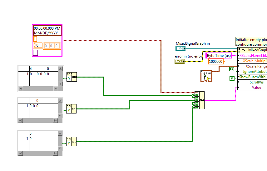
To avoid reconfiguring the graph of mixed signals, everytime I open the app, I wrote a Subvi to programmatically format the chart. I pass a reference to the graphic indicator of mixed signals and try to adapt it to look how I want. The indicator has been designed as a cluster of analog waveform 1, 2 bus waveform Digital 5 signals 1 waveforms digital bus 3 and 3 different digital waveforms. The Subvi is called inside the host VI using a statement box controlled by the 'First Call' function. Then host vi bed a U32 to the target-to-Host DMA FIFO, formats the data in the correct order and the beams while an indicator of mixed signals. During an attempt to format the chart programmatically, I get errors in property not valid which seem to depend on State. Unfortunately, the documentation of the properties seems to be quite uneven for errors I get. The Subvi attached through the following sequence:
1. configure the shared axis and shared properties (IgnoreAttributes, ShowBusseswithLines)
2 set up the area of tracing analog scale Y (superior plot, area 0? documentation is inconsistent on this point)
3 set up the area of tracing digital scale (sector 1) Y?
4. name the digital bus (3 in total, should be numbered 0-2).
5 name the plots
Correctly all steps 1 through 3, but I get an error when you try to set the Active Bus to 0--> ' #1077 Error, invalid property (Bus Active)»
I tried to set the Active plot area to 1 before setting the bus, and I get the same error.
But then sometimes if I rerun the VI host without change, the Subvi ends correctly (even if the area of the scale becomes huge and empty). The only way I can remove the errors is to set the for loops to iterate 0 times, allow the host VI run a few cycles, stop the host VI, remove the constants 0 and run again. And then there is no property errors.
I then tried to create a constant of mixed signals with the correct sequence of the empty slots and it allows to set the MixedGraph::Value property at the beginning of the Subvi. Now error #1077 occurs at the level of the active node before Plot Bus Active node. The thing first on the definition of the constants of iteration 0 does not help when the value property is an initial value.
Here are my questions:
1. the ActivePlotArea property must be configured to use ActivePlots or ActiveBusses, or is that only for sizing and moving areas of land?
2 - is ActiveBus ActivePlot to define first of all necessary to property? for example, if I have ActivePlot = 0 (for analog plot), the ActiveBus property will always fail?
3. what else is necessary for the property ActiveBus of function call?
4. why the Subvi is failing the first time but succeed during subsequent calls without be initialized does not yet reach every time after you initialize (except for loops are set to 0 and Subvi finishes once)?
5. because I show a legend of the plot, I don't want the names of digital signal appears again in the scale box Y. How can I hide the names but to allow the plot area to extend completely to the legend of the plot rather than leave a large area of wasted white space?
Hi Nick,
The reason your Subvi does not work, it's the bus you want to change do not exist when you run.
If you want to run this sub - VI like initializer, you must first initialize all of the plots you will be change.
I've included a small example of how to achieve this by grouping together a constant of analog waveform with some constants of digital waveforms and food nerd in the property "value" Mixed Signal curve.
Maybe you are looking for
-
Satellite A660 - Power button after
For awhile, my laptop was power in, on and off, without any interaction. I think that it is a faulty power button. The button is extremely sensitive and will be able to even if you press the surrounding Panel. My question has anyone experience this p
-
When I try to run SFC/scannow, it will start and then gives me a message that it cannot run this program... I use build 10041' and nothing has changed since I installed it... I was wondering if this is a common problem or what? Any help is appreci
-
Tengo problemas con the hifi conexion con mi netbook
happens that pasa are estoy con una Señal hifi con permiso para ocuparla pero pasa al poco tiempo produce me the signal error
-
My Windows Vista says no real preload even you the Diagnostic report says that it is
I did a Diagnostic report to ensure that it was following the report says it isMy laptop was made by Hewlett-Packard and was brought around 2008-2009, I can't give a goodAs it has been a Long time ago because of this Theres no disc or the Code to ent
-
Vantage system update think 5.06 fails to install
When I tried to run 5.06 TVSU I got an error message at 10% of the scanning process, which TVSU could not complete the process of scanning to see if there were updates available. After many attempts to find the updates, I uninstalled TVSU 5.06 think