Signal separator problem
I use a signal splitter in the given file. It separates the signal into six parts. I use a waveform chart to show the signals. But the only exit from split is shown on the chart... Five others are missing... Why... ? How can I get six waveforms on the output... ??
As far as I know none of the screws on the standard pallets provide no direct way to create a three-phase signal. Six sources, all with the same frequency and different phases and amplitudes, is a simple way to do it. Alternatively, you can create a table of the phases and amplitudes and thread in a loop with the signal source VI inside the loop.
I'm not a fan of the Express VIs for this kind of things. First, they have the flexibility to run the lower floor screws on the range of Signal Processing. The Type of dynamic data hides the data structure he wears. According to what will be done with the data later, I prefer the waveform data type or simple tables. And the huge icons occupy too much area of block diagram.
Note that the use of tables as in this example change the x-axis in the charts. The units are clues of paintings, the equivalent of 1 sample per second.
Lynn
Tags: NI Hardware
Similar Questions
-
How can I get my 12 items Editor to open in El Capitan on mac? It signals a problem. As suggested by the Apple support, I've trashed previous preferences and tried to restart, but to no avail. They told me to return the trash preferences and contact adobe.
Adobe has not yet been able to offer suggestions of what-so-ever, aside from telling me that it is there no real person for this product customer support and that I should try this forum. I hope that, apart from the many people with the same problem, there may be even one person out there with a solution!
I bought the Publisher of 12 elements in March 2015 on the Apple App Store. Apple has confirmed that there is absolutely nothing wrong with my Mac. He has had problems since bought and installed on Yosemite, now the new O.S. El Capitan is installed, and 12 elements editor now refuses to open at all.
My opinion is that if Adobe and Apple do not provide professional support for the products they sell to us, then they should say at the outset that there is no support for these products. This is not the first time that I was sold an adobe product that doesn't have any product support, product durability or reliability of product.
If all goes well there's someone out there who can help me!
Thank you!
Mr.L.
Little Giant Productions.
As you have the version of the App Store, you will need to re - install. Your download should always be available in the Mac App Store under "purchases".
Apple has had problems with security certificate expired affecting all applications downloaded from the Mac App Store. Here's a solution that worked. Give it a try by following each step:
I had the same problem on the Mavericks and your suggestion worked for me. FYI, I deleted the items, empty trash, disconnected from the App Store, restarted the computer, signed in to the App Store, then downloaded items. I use OS x 10.9.5 and 11 elements. Hope this helps!
-
Yet WT8 - WiFi signal reception problem
Hello
I hope someone could help me!I bought a Tablet still 8 a few weeks ago and just after the first start, I found a problem in the reception of the wireless signal.
When she acquires the signal, there's always between 1 or 2 marks in the indication of wireless in Windows 8.
I tried initially change the card wifi settings (which is disabling the power saving mode) but without any improvement.I compared the tablet with another identical of my colleague and in the same position as his Tablet acquired the signal with no problems, then the mine has not signal.
So I decided to sent the tablet in support, but they have not found any problem.
They performed a restore of the system and then sent to me.When I restarted, I found the same problem as before.
I have already installed the latest available Council broadcom driver, available here on the website, but also this way nothing has changed.
Y at - it a driver update or the setting that I can do to fix this?
or it's a HW question?Thank you for your help
Hello
Check if the WLan option in windows power management (using Central) has been defined in the performance.
You should also go to Device Manager-> card WLan-> properties-> Advanced tab
Here you will find a few options that could improve the performance of Wlan. -
Tecra M2 and wireless network - signal strength problem
Need advice buying wireless kit.
I have a DSL phone line connection and I am currently using a Speedtouch USB modem connected to my workstation down.
I have a laptop Toshiba Tecra M2 with construction of wireless support. I want to be able to share the internet connection which comes in the workstation down. I guess that my options for the workstation are to use a DSL wireless modem to share the internet connection or to use a PCI card in my computer. I tried them both.
I first tried to set up an infra mode network with the laptop using a LinksysWAG54G which was connected to the telephone line and a computer. But the problem with that I was t couldn't do accept the subnet mask that my ISP (Lixxus) provided 255.255.255.255 (PPoA). This modem has all the masks of SN in a dropdown list, but mine isn't in this list. I returned this modem.
I tried then set up an adhoc network purchase buy a PCI Wireless card for my desktop, and internet connection sharing etc. on the workstation. However, while it worked, and I could see the desktop of my laptop, the problem has been the wireless range. The signal disappear when I wore the laptop in the back room on the first floor. It would have been a distance of 10 meters in a straight line between the laptop and desktop. There are walls two bricks and a floor between the two machines. It seemed hopeless, so I sent the PCI card.
I'm not sure what to try next.
Any suggestions that I could try next?
Suggested hardware?
Signal strength - could the problem be that the antenna in portable insufficient Tosh - it too small?
Hello
I have the same situation at home. The best solution for this is to use the wireless router. Here you have the possibility to connect several computers desktop or laptop. In this case the configuration of wireless connection is very easy and it works fine. I also use it at home and in front of my house with no problems.
-
purchase card form signals separately
Hello
As you know that stereo can choose two signals simultaneously. I am interested to receive signals using sound card and display them separately on vague shape graph. Can anyone please help me to accomplish my task.
Thank you.If by separately, you hear two different graphs so I think that stereo sound is acquired as a table (2x1D waveforms). Simply use the function array under the table palette index to obtain different waveforms, then each of them to their separate parcels of wire.
Craig
-
Hi all
I have a problem strange connection of signals to the slot machines. I have the following code:
Container container = root->
m_pForeignWindow = (ForeignWindowControl *) (container-> at (0));m_pForeingWindow is not null here
Boolean success = connect (m_pForeignWindow,
SIGNAL (windowAttached (screen_window_t, const QString &, const QString &)),.
This,
SLOT (onWindowAttached (screen_window_t, const QString &, const QString &)));))success is true here
success = QObject::connect (m_pForeignWindow,
SIGNAL (touch(TouchEvent *)),
m_timeline,
CRACK (onTouch(TouchEvent *)));success is false here
Research with the debugger, I got the following message:
Object::connect: No such signal bb::cascades:ForeignWindowControl:touch(TouchEvent_*)
but this signal exists for all objects in VisualNode... What I am doing wrong?
Kind regards.
See if it actually compiles. FDI in the current beta version is infamous for being reported wrong these errors, so I suggest to turn them off.
Window-> Preferences-> C / C++-> the analysis of Code-> Qt syntax problem
-
ADC signal formatting problem!
Personal salvation OR.
IAM having problems trying to measure tension in the port adc to a PIC 18F4550 through Labview.
the fact is that iam like a beginner in programming G, and I don't know how to maintain the chain that iam get VISA read module and therefore iam does not receive the data in the appropriate form.
IAM using an 8-bit adc, so I pretend to read the 255 when iam in FS. but iam get something like "48", as you can see in the attached screenshot.
I thought about it. I don't know exactly why but it seems that the number of the indicator and all the conversion in takes only a part of what im sending.
It worked simply by attaching a string indicator in the outpin of the VISA-READ. It was the first option I thought the first time, but it did not work this time.
Sorry for the flight of your time and thank you for the help!

-
gdgdgdgdg
Hello
Sorry to inform you, but only of HP will be able to provide a solution. They are responsible for the pilot to making their products within Windows 7. You need to contact HP support for more information when they have the appropriate printer drivers that are compatible with Windows 7.
Regards, ~ Alex T. ~.
~ MVP Windows desktop experience ~ -
RV042 subnet separation problems...
Hi all, I have my RV042 with 2 subnets 192.168.1.0 and 192.168.2.0 and I neet a way to block traffic between...
Welcome to the community of Cisco.
If possible could you give us a little more information. If you could explain how the two networks are connected as there is a managed switch, are these subnets of a VIRTUAL LAN, which is the IP address of the gateway for each netwrok and so on.
There are a ways efw we can prevent a subnet to talk to each other, a solution would be by creating an ACL in the router, but this only works if the directly managed router traffic between networks. In other words, if we do not use a Layer 3 switch for example.
If the router handles all the traffic, then you should be able to do something like this:

Note that the range is for all IP addresses. If the IP of the router is this range you block yourself.
Hope this has helped.
-
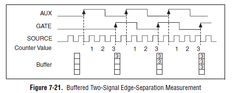
bad examples in two documents of signal edge separation
In the folder 'Two signals separation edge' examples are not two examples of signal.
They are two edge separation measurements made on a single signal.
I'm for any edges ofrising of separation between two signals Encoder on pairs of consecutive 1024 pulses. I couldn't find an example for this.
Is there something I could try?
Looks like you want something like this (Image of the M series user manual):
If you want to measure a finite number of impulses, you must use the 'soul two edge separation - Finite.vi buffered"is shown in the screenshot in your example finder. You must connect your two signals to the entries ' to the ' and 'GATE' of your meter. On many boards (for example, plugin M series), the default lines used are:
CTR 0:
To THE: PFI 10 (PIN 45)
PORTAL: PFI 9 (PIN 3)
CTR 1:
TO THE: PFI 11 (PIN 46)
PORTAL: PFI 4 (Paperback 41)
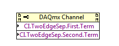
If you don't want to use the default values, you can edit the lines used with a channel property node DAQmx PFI:
The examples you linked measurement of separation edge on two different signals in the manner illustrated in the diagram above.
Best regards
-
Multichannel data acquisition and 2D signals
Hello
[Use of labview 2011 license academic with NI9234 and cDAQ-9178].
I'm trying to read, display and record the signals from two isotronic accelerometers and a microphone at the same time for future signal analysis (FFT, etc.). I wish to display data of vibration and noise signals in real-time at 44100 Hz sampling frequency and display a waveform of final sampling, which takes about 40 years. I would like to then write the data to a file.
The associated block diagram, attached vi. I could view real-time each accelerometer and sound using iterations of the loop and split the signal. Unfortunately I record three channels of data in a table unique 1 d-wave form. It seems that the data is saved as iteration1 (ch0) .iteration1 (ch1) .iteration1 (ch2) .iteration2 (ch0) .iteration2 (ch1)... and so on.
Although I could show all three signals separately in the waveform graph, but I prefer these data to save as table 2D-waveform (each channel in a separate column).
I believe that this issue has been raised here (http://ni.lithium.com/t5/LabVIEW/Concatenate-2D-data/td-p/873409) unfortunately no solution has been proposed. How can I record the signals of data acquisition in 2D waveform?
Thank you.
I think to represent vi attached a solution architecture producer consumer for the problem mentioned above. Just thought I'd share to those who can live a similar situation that I had been faced.
-
Satellite Pro m USB devices connection problems
Hello visitors and insiders.
can someone help me, please? - or are the causes of the problems of programmed BIOS is not perfect?
I put on the USB Ports (I tried all 3 Ports) after correct installation of the most recent drivers for devices and the BIOS and chipset.
I tried MAGIX encoder by USB and PINNACLE for USB encoder - both signal-request-problems and the two could not shut down the system after connecting with USB and close with her current for USB device.I tried this on different WinXP installiations (multiboot) - but on all systems even.
The same reaction has been, as I have connected a special CUSHION cooler for laptop with additional USB Ports.
The CUSHION cooled - but the USB Ports do not work for all devices (devices I am familiar with the)
Ports of origin of the laptop, has failed to TRIM, too). (worked directly devices: mouse, webcam, keyboard, drive hard usb)What should do? .. If anyone know Somethin ' help... I will be very happy.
Thank you very much!!! (Sorry for my English is not perfect)
Ben
Is what model of laptop exactly?
Have you installed Windows yourself? Or it was preinstalled?
Looks like it's a software problem, bad drivers USB can at fault.
You are able to back up your data and run recovery?
-
I can acquire a signal of 2 wire vibration or accelerometer sensor with a NEITHER-9208
Hello
I have a vibration of 2-wire sensor, this sensor gives me a 4-20mA signal, 4 my = 0 ips or any vibrations present and 20 my shows the beach from the tip of vibration is present, my ips for this sensor range is 0 - 2.0 ips, initially, I had chosen the 9218 OR to set a connection IEPE, but this module have only 2 channels , so the NI 9208 has 16 channels, so my question is, can the NI 9208 acquire this signal without problem?
The 9208 is the correct unit to use. See the manual (fig3)? How to connect the two sensor wire (loop). Need for an external power supply for this unit. For the min/max of the supply voltage, see the technical details of your sensor. (24V power is common, but it must meet the requirements of your sensor!)
-
How to build a parser of vector signals PXI using different module combinations
Normal
021
fake
fake
fakePT - BR
X NONE
X NONEMicrosoftInternetExplorer4
/ * Style definitions * /.
table. MsoNormalTable
{mso-style-name: "Table normal";}
MSO-knew-rowband-size: 0;
MSO-knew-colband-size: 0;
MSO-style - noshow:yes;
MSO-style-priority: 99;
MSO-style - qformat:yes;
"mso-style-parent:" ";" "
MSO-padding-alt: 0 cm 0 cm 5.4pt 5.4pt;
MSO-para-margin-top: 0 cm;
MSO-para-margin-right: 0 cm;
MSO-para-margin-bottom: 10.0pt;
MSO-para-margin-left: 0 cm;
line-height: 115%;
MSO-pagination: widow-orphan;
font-size: 11.0pt;
font family: 'Calibri', 'sans-serif ';
MSO-ascii-font-family: Calibri;
MSO-ascii-theme-make: minor-latin;
MSO-hansi-font-family: Calibri;
MSO-hansi-theme-make: minor-latin;
mso-fareast-language: EN-US ;}Normal
021
fake
fake
fakePT - BR
X NONE
X NONEMicrosoftInternetExplorer4
/ * Style definitions * /.
table. MsoNormalTable
{mso-style-name: "Table normal";}
MSO-knew-rowband-size: 0;
MSO-knew-colband-size: 0;
MSO-style - noshow:yes;
MSO-style-priority: 99;
MSO-style - qformat:yes;
"mso-style-parent:" ";" "
MSO-padding-alt: 0 cm 0 cm 5.4pt 5.4pt;
MSO-para-margin-top: 0 cm;
MSO-para-margin-right: 0 cm;
MSO-para-margin-bottom: 10.0pt;
MSO-para-margin-left: 0 cm;
line-height: 115%;
MSO-pagination: widow-orphan;
font-size: 11.0pt;
font family: 'Calibri', 'sans-serif ';
MSO-ascii-font-family: Calibri;
MSO-ascii-theme-make: minor-latin;
MSO-hansi-font-family: Calibri;
MSO-hansi-theme-make: minor-latin;
mso-fareast-language: EN-US ;}I understand
Vector signal analyzers OR consist of 2 or 3 separate PXI modules: 1
digitizer, 1 buck converter of RF frequencies and 1 generator of signals (model 5663).1. can I use digitizer and signal
generator general purpose oscilloscope and generator of signals separately?2 may I build my own VSA by choosing
different combinations of scanners and the signal generators? Or replace the signal
generator by an arbitrary signal generator?3. I
intend to buy a digitizer/oscilloscope and an arbitrary signal generator
analysis of response of frequency on the transformers. Later I plan to
buy a step-down converter frequency and build a vector signal Analyzer. Is this possible?Hello
The frequency IF the 5660 and 5661 (it's the same thing) is 15 MHz, with an instantaneous bandwidth of 20 MHz. The difference between the 5660 and the 5661 is located in the digitizer that accompanies it. The 5660 uses the PXI-5620 digitizer that has a sampling rate 64 MECH. / s and a buck converter of digital frequency limited to 1.25 MHz of bandwidth. The 5661 uses the digitizer PXI-5142, giving you a MECH 100. / s rate and a PSO allowing digital downconversion circuit and the decimation of the full bandwidth of 20 MHz.
The common comment in the SBA above is the RF PXI-5600 frequency step-down converter which is a superheterodyne architecture of three floors. OL is for the three stages of this module are auto-approvisionnées in their own country. The architecture of several step allows for rejection of the improved image and filtering at the expensive of a noise floor slightly higher due to the signal path more complex. There also an OCXO on board, this gives him a time reference more precise - noise reduction phase etc. The PXI-5600 by itself is wide from three locations.
The SMU-5601 since SMU-5663 step-down is designed based on the single frequency step-down converter and resumes from a single location. The celled frequency step-down converter gives you improved noise floor characteristics and a better dynamic range, with the rejection of the image fees, having does not simply because there is only one step. The LO is provided by an external module in this case for several reasons. Have a separate external LO allows more modularity in your system, as well as the ability to share a single LO generator between several vendor-specific attributes. This opens the possibility of MIMO applications. The internal of the NI PXI-5600 LOs are not shareable and therefore cannot be synchronized between several PXI-5600 s. The PXI-5663 (all three modules) takes up the same amount of space in the slot as a single NI PXI-5600 without a digitizer.
The PXI-5154 is indeed a powerful scanner, given its instantaneous bandwidth of 1 GHz. Remember, however, that the connector Active Directory on this digitizer is 8 bits, compared to the 5622 which is 16-bit. If you need more resolution is of course entirely depends on your application. The PXI-5600, as SMU-5601 is controllable as a buck converter stand-alone frequency using the DAMA API OR. You will need to program your application with the scope API for use with PXI-5154 OR and the API de DAMA. A few other caveats to note is that there is no PSO on the PXI-5154 so you can't enjoy the Equalization filter to correct the frequency of the NI PXI-5600 response. Also, as I mentioned above, the frequency of YEW of the NI PXI-5600 has 15 MHz with a bandwidth of 20 MHz - processor 1 GHz bandwidth on your digitizer will be somewhat of an overdose of the IF signal.
While you're dead on with the advantage of modularity, I would take the time to really meet your search application and ensure that different choices of module and their combinations to meet these needs.
Hope that helps!
-
Amplitude measurement of a continuous signal in a given time window
I'm working on an acquisition system that acquires a continuous signal of 250 kHz. My goal is to measure the amplitude peak-peak of the first reaction of signal, the problem with my setup, this is the first part of the signal is always higher than the part of the signal that I'm interested. If I try to use the measure of max from Ridge to ridge of signal VI then responds with the measure of Ridge Crest of the initial part of the signal. See the attachment for a better understanding, I would still like to view the raw signal as is, but I would like to measure the peak voltage at peak of the signal between the yellow sliders.
Thanks in advance...
If transient initial always occurs in the first 12 microseconds, you can use any subset of table or similar wave function to retrieve the last part of the wave. Then use the measurement from Ridge to Ridge on this subset.
Lynn
Maybe you are looking for
-
Since the upgrade to iTunes 12.4, which occurred automatically when I upgraded to El Capitan, a move, I regret a hundred times a day. I find that I can't edit the title and other information of movies (corporate videos that I use to show potential cu
-
I'm not stupid. I know how to enable or disable password remembering thing in options, but it simply doesn't. He remembers the passwords and logins from sites that I decide to do not. I can restart my computer and Open firefox and go straight into my
-
I have my mailbox gmail automatically uploaded to my mailbox of EO. Each message in the Inbox gmail Downloads box of 2 or 3 times to EO. Delete the OP3uidl.dbx file does not resolve the problem. I would appreciate any other suggestions.
-
HP Compaq dc7900 Small F.: create a recovery disk
Hello I have a rebuilt computer that was installed originally windows Vista OEM. And then installed Windows 7 64 - bit has been renovated, but I can't find HP Recovery Disk Creator. What should I do if will crash hard drive? Is possible download HP R
-
Need help! I had a program running one of my computers. Need to be accessible outside of here. I put the DMZ at 192.162.1.100 (which is the ip address of the runing machine program) MY ISP got a static IP address. Used to work with my old WRT54G... d