Differential using NI 9205 using FPGA
If I need to make a differential measurement, do I need to subtract the corresponding entry to this?
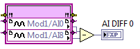
(This could be executed on FPGA)
Are there problems (such as clipping) if my input range is small, lets say ±200mV but my IO is floating in, say, 3.0V on AI0 and 3.1V on AI8?
To take a differential measurement with FPGA, you first need to go to your project and right-click on the module and access its properties. You should see a list of all your channels, as well as their input range and terminal mode. The value the + channel for everything that match you are eager to use it as DIFF and file I/O node just to the canal +. You don't have to do a manual removal.
Not expect problems with the behavior you described.
Tags: NI Hardware
Similar Questions
-
Rare use FPGA build without sample FPGA build
Hello
I hope I can formulate my question in the right way. I want to test a routine of FPGA and do not always want to compilate hole streaming project (e.g., construction with bus register etc.). Is it possible to only build a simple FPGA bitfile (simple while loop, some fifos, my code) and test on the device of the USRP RIO or what I need to use the basic FPGA in Streaming Xcvr as base build? This would be really shorten the compilation time to test the new code.
I hope that my question is understandable.
Concerning
Etuel
Yes, you can start from a blank VI FPGA and develop FPGA code similar to other LabVIEW FPGA targets. There are a few things to point out:
- You will not be able to use the host of the project example screws if you do this. If you don't have the FPGA of the sample project code, the host screws will not good FPGA logic to connect with.
- I recommend not to put any code in the domain of Data Clock. Data clock requires the USRP RIO IDLs configure this field of clock. To do this properly, you need the '' necessary '' of the FPGA block diagram section. It is easier just to avoid all this. To use the clocks faster than the clock of 40 MHz, derive a new clock, the clock of 40 MHz.
Good luck!
-
Rate of update NI 9025/9113 IO using FPGA in scan mode
I have an old CRIO manual indicating that the scanning speed is 1 kHz. The new materials (9025 and 9113) can go faster than 1 kHz?
Page 17 of CompactRIO Developers Guide will give you the best explanation. Anything more than 1 kHz will have serious consequences on your CPU usage. It is recommended whenever you want to run the application using LabVIEW FPGA programming faster than 500 Hz rates.
-
cannot create the file of text using fpga
I spent an entire day to solve this problem, if someone help me please!
I have two types of registration data, movement and time. I looked up NI EXAMPLE FINDER and copied the format to create the text file. but the file dialog box is not pop up. So I thought I did something wrong with the function of the dialog box, but when I copy the first part of my code, the dialog box appears. If anyone can check my host vi and tell me what is the problem? I downloaded the target vi as well.
I use crio 9074, and vi is made in mode of fpga.
Hi Ultrafrog,
The RT vi or vi FPGA screws?
In FPGA, you cannot file i/o. But you should be able to do this in your vi RT it seems you are trying to apply it on the FPGA.
-
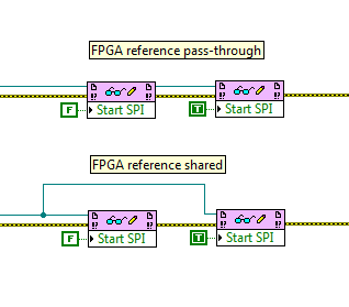
Definition of registry FPGA: using the reference transmission
Question of Labview FPGA basis. When I use FPGA read/write control to set a record in an FPGA, is there a difference between using a FPGA reference 'place' (connection FPGA VI reference Out on a block from the FPGA VI in the next reference) or directly to sharing the same node of reference? Image below illustrates the two spare connectors: they are functionally identical? If so, why is there an outside reference? Is it just to keep the more neat wiring diagram?
Yes, these two are the same, they would be for any reference type in LabVIEW. The top version is much more clean, however, isn't? Also, if for some reason you do not want to use error wire, wire reference here provides another way to enforce the order of execution.
Also note that you can drag down the node to read/write to read and write several items in a single node, and they can be a mix of reading and writing.
-
Effective use of the FPGA read/write
I am writing an application for a CompactRIO real-time and I am looking for ways to simplify my code and reduce the CPU usage. I use FPGA to do much CAN e-mail and signal processing, then I have a VI running on the real-time processor that reads values in the FPGA, does some processing and outputs data in the FPGA. My code running on real-time parallel uses several loops running in a master/slave architecture. A single loop reads all necessary information in the FPGA in indicators and writes the values of the controls in the FPGA. The other loops read entries and manipulate the outputs via local variables.
My question if it would be more effective to get rid of the loop which is dedicated to the communication of FPGA and has of each loop to read and write directly on the FPGA. If I use a reference block FPGA open and use the reference of the output in several loops, each read/write operation block others until it's over? Each output is changed only in one place in the code, but there are several entries that are used by multiple loops. It is even more effective for each loop of read/write for the FPGA on request? How will this affect determinism?
Thank you
Jon
Jon,
Read/write controls is not deterministic, but I think that your previous method should work just fine, as long as you have that unique writers. If you have multiple writers, you start affected by race conditions.
I don't think you will see a significant improvement in the performance/CPU in the alternative method. You would see big performance gains if your master loop reads more slowly indeed, but it's always a compromise.
-
Using more 4 for MyRIO quadrature encoder inputs
Hello
I am doing a project where I need to drive 6 motors, each with feedback from encoder quadrature to control the position.
Currently, I use the VI MyRIO encoder, but there is a limit to 4 encoders. What is the best way to read 6 encoders simultaneously with the MyRIO?
Thank you
Timothy
If you must change the FPGA myRIO personality you have a few options.
The best option is to start with the FPGA myRIO sample project, add and delete components according to the needs and then build your bitfile. No registry (LV FPGA control / indicators) you do not change will still work with the Advanced IO screws and screw Express. To use the new bitfile (FPGA personality) you must update the Reference of VI FPGA opened in myRIO Open.vi v1.1 (LabVIEW 2013\vi.lib\myRIO\Common\Instrument Driver Framework\myRIO v1.0\myRIO v1.1 Open.vi).
After having done all this time, you use an Express VI myRIO or Advanced IO VI it will use your custom bitfile. All peripheral channels that you left in place will continue to work. You have deleted all channels will always appear in the screws, but will not work (they will probably throw errors when running) and all new channels that you added appear in the screw . New channels, you will need to use FPGA read / write nodes for read and write configuration data and register you created in the FPGA personality. These changes will persist on this computer until you change the Reference of VI open FPGA to the bitfile original.
Let us know if you have any questions about all of this.
Thank you!
-Sam K
Join us / follow theGroup of pirates of LabVIEW on google +
-
Using NI 9512 with Modulation of frequency step Position? (cRIO)
I am trying to activate a scene for an experience that requires a frequency on the step signal modulation to a stepper motor. I use a cRIO-9076, a NO-9512 and driver to drive stepper P70530 OR third party engine step by step. step VI FM Position seems to be exactly what I need for my application, but I have some difficulty working with him and the NI 9512.
Is it possible to use the 9512 in an FPGA VI? THE ETC. requires use in a single-cycle timed loop, so I want to send the step and Direction signals directly to the FPGA of e/s for the 9512. The 9512, however, does not set up to use FPGA to IO. In research, I found some examples using the 9501 instead of the 9512 module, but this would require a lot of new material that I don't think I should buy.
I would greatly appreciate some suggestions as to what to do and even of ideas as to how I could fix this problem.
Thank you
Enan
Hi Enan,
When you use the 9512 in scan mode, the NI SoftMotion Module will send a position setpoint at 9512 once each evaluation period (the period of analysis is usually around 1 to 10 msec). The 9512 does not generate a path; It just interpolates between the values given. It is your responsibility as the programmer to ensure that values being sent to the 9512 are sinusoidal. To do this, the easiest method is to use a contour move and fill the contour buffer with a profile of the sine wave. You can generate a sine wave using something like the model sine VI profile. He ship in SoftMotion examples that show how to perform a move of contour.
In my view, contours movement require SoftMotion Standard or Softmotion Premium. If you have SoftMotion Lite, the only way to get a real path sine wave is to build the model of the sine wave on the host of the RT and send him to the FPGAS in a FIFO. You could also build the model of the sine wave directly on the FPGA. You will then write the sine wave point by point to the Write 9512 method. It is more difficult to achieve, so if you have SoftMotion Standard or Premium, I would recommend the move approach outline.
Thank you
-
Current versions of software:
LabVIEW 2014 SP1
LabVIEW FPGA 2014
Xilinx Vivado
Hi all
I plan to interface my FlexRIOs to the software programmed in C, then the C API FlexRIO is excellent.
My question is more economy of memory sake.
I have a PC with Visual Studio, I want to add the minimum amount of software development.
If I have a station (a separate Visual Studio PC PC) FPGA development with all LabVIEW software necessary to take the step of the use of the generator of the C API to create the necessary files of C and H, should what software I on the development PC Visual Studio in interface with the files in the generated C API?
If all goes well, it's just (from the help)
What you need to get started
- Drivers for devices OR RIO August 2013 or later
However... The help of the C API, it gives me the full list of the software including LabVIEW and LabVIEW FPGA... (below)
What you need to get started
In addition to a RIO device like a CompactRIO reconfigurable chassis, a Single-Board RIO device or RIO PCI or PXI hardware, you need the following software to use FPGA Interface C API.
- LabVIEW 2009 SP1 or later (32-bit only)
- LabVIEW FPGA Module 2009 SP1 or later (32-bit only)
- Drivers for devices OR RIO August 2013 or later
- Operating system supported development
- Windows 8 or 8.1 (32-bit or 64-bit)
- Windows 7 Professional (32-bit or 64-bit)
- Windows Vista Business (32-bit or 64-bit version)
- Windows XP Professional SP2
- Windows Server 2008 R2 (64-bit version)
- Windows Server 2003 (64-bit version)
- Target supported OS
- Supported C/C++ compiler
So I have LabVIEW and LabVIEW FPGA on the development PC?
(If all goes well no....)
Thank you
Hey Colonel1013,
With the C API, you only need LabVIEW to build a bitfile and run the generator of C API tool, but LabVIEW is not required to run. That is, you need all the software listed, but it must not all be on the same machine. You can transfer the file lvbitx and the .c and .h files generated on another machine where you need only NOR-RIO and Visual Studio installed.
Sebastian
-
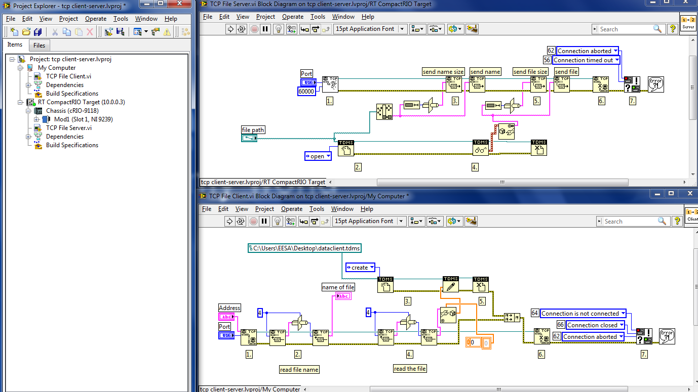
How to send files TDMS using the TCP/IP protocol
Hello
I work with the cRIO-9025, cRIO-9118 chassis and module NI 9239.
I did an acquisition (voltage) where data are in 1 d Wfm SGL. I saved these data using a PDM file, but now I want to send this file to another computer (in this case mine) because the file is stored in the target. I have implemented this example:
http://zone.NI.com/DevZone/CDA/EPD/p/ID/2842#0requirements
The problem is that the tdms file is created but it has all the data. I have attached the image of the program. The program is in the other (not that I use to make Acq) to make it easy and then works when it works.
* The file name of the client is not used because I had a conflict with the path.
What I'm looking for, is to make an acquisition of 10 minutes every 30 minutes and then send this data to another computer (or other). I don't know if it's the best way, is perhaps better to send data at the same time as the acquisition is made, but my teacher told me that are easier if I send the file when acquiring ended. Acq, I use FPGA and RT.
I would appreciate your help. Thank you!!
-
can I set up an amplifier to lock using the PCI-7831 RIO map?
Normal 0 21 MicrosoftInternetExplorer4 / * Style Definitions * / table. MsoNormalTable {mso-style-name: "Table normal" "; mso-knew-rowband-size: 0; mso-knew-colband-size: 0; mso-style - noshow:yes; mso-style-parent:" ";" mso-padding-alt: 0 cm 0 cm 5.4pt 5.4pt; mso-para-margin: 0 cm; mso-para-margin-bottom: .0001pt; mso-pagination: widow-orphan; do-size: 10.0pt; do-family: 'Times New Roman' ;} "}
Hi all
I use FPGA, PCI-7831R module, I can implement locking an amplifier using the PCI-7831 RIO map?
Kind regards!
SUN
Hey,.
The following link shows an example of a lock-in amplifier set implemented on a cRIO with 9233 module.
-> http://decibel.ni.com/content/docs/DOC-1762
Hope this helps,
Christian
-
Broken the FPGA VI but the empty error list
Hello!
I'm trying to run a vi which includes a 'Open FPGA VI Référence' function. However, an error and it says that "not compiled FPGA VI. When I try to compile the FPGA VI a message saying "The VI is broken". I try to run the FPGA and when appears in the error list, there is no error or warning in the list, although the name on the fpga includes the Red 'X' ('show warnings' is checked). Any help?
I'm using Labview 2013.
Pablo
Hi Pablo.
Sorry for my delay in responding, you managed to get the respected FPGA.vi yet?
To answer your questions, if the project is ok with an empty FPGA.vi, then in theory, your hardware is configured ok. However, due to the vi being blank, you haven't tried to use one of the modules on your system, so it can introduce errors. The most common mistake is differentiation of mode Scan Mode/FPGA by installing the project in the first place. Also be aware that not all FPGA targets supports everything, for example some dislike for the rows that have an index to calculate the number of iterations, rather than a constant wired at the entrance to "n".
Out of curiosity, why you place every measure in the DMA separately and also specify address? Is there a reason you don't just place all the measures in a table and put everything in the DMA, then divide the table on the other side?
Generally speaking I don't think that incorrect programming should never cause LabVIEW crashing and you should always report the problem to the OR in order to take a look and see if they can fix it.
Hope that you managed to get your problem sorted and again sorry for the late reply.
Darren.
-
HY all!
I have a few questions using Xilinx compiler tools.

The reason why I want to use FPGA is to get the analog measurements of two modules NI 9205 and also filter these measures. Modules are configured to run in terminal diff mode, while the other parameters of this module are set to default values (+/-10 V etc.).
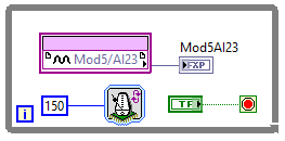
2.1 when I try to compile the program easier - read one analog measurement every 150 US, see the figure below - just compilation takes too much time, namely fear for a few hours, specifically, compiling stucks on mapping. I followed my PC performance, processor is about 20% 3.84 GHz, while the memory is on 10% 31.9 GB. Q1: is it possible to configure the compiler to use as many resources as possible PC?
I'll post probably questions once I managed to get this simpler program to work

Thank you in advance!
Best regards
Marko.
Hello
What operating system do you use? I read somewhere on this forum that windows 8 and possibly windows 10 are not taken in charge by xilinx compilator.
I have simular problem faceing with the compilation of the code. On Windows 8 compilation take over 50 minutes and not finished yet. Then tried to compile the same code on Windows 7 it only take 10 minutes. -
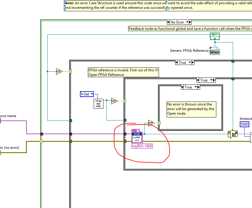
LabVIEW FPGA SPI accident - SPI OR IP address for example - R series OR
Hello
I am trying to run the series R - sample project NI SPI FPGA Simulation.lvproj that comes with the SPI IP OR on a real FlexRIO FPGA SMU-7976R target with an attached digital adaptation NI 6581 B Module. The example is for a PCIe-7841R but I wore during my target FPGA, follow these steps and made additional changes to try to make it work with my set-up. I learned that FlexRIO FAMs CLIPs do not work with nodes in office had so I know I can't simulate the project originally planned so I will try to use FPGA to e/s node host side (open FPGA vi reference) to implement the actual hardware.
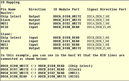
My first question concerns my configuration of the adapter module e/s and selection. I added the IO Module (NI 6581 B: NI 6581 B channel) for my project and selected the channels as shown in the table below. I have a real physical hardware connection as described below using two NI SHC68-C68-D4 cables and a break-out Board.
I changed the names as well:
I selected these DIO channels because I wanted the DDCA connector to be the master and the DDCB connector to be the slave. In addition, in this CLIP every eight channels of i/o has a write enable signal. I have not used the Port configuration because I needed 4 available DIO channels and I saw DIO0-3. Is my logic of selection of channel vs correct Port here?
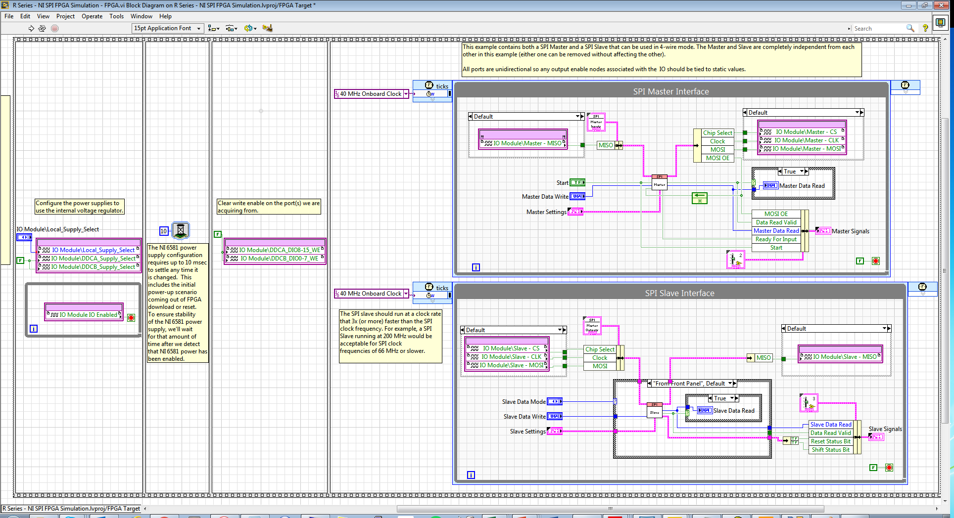
Following the same strategy that examples FlexRIO/NI6581B, I changed the FPGA.vi to include initialization outside of timed loops:
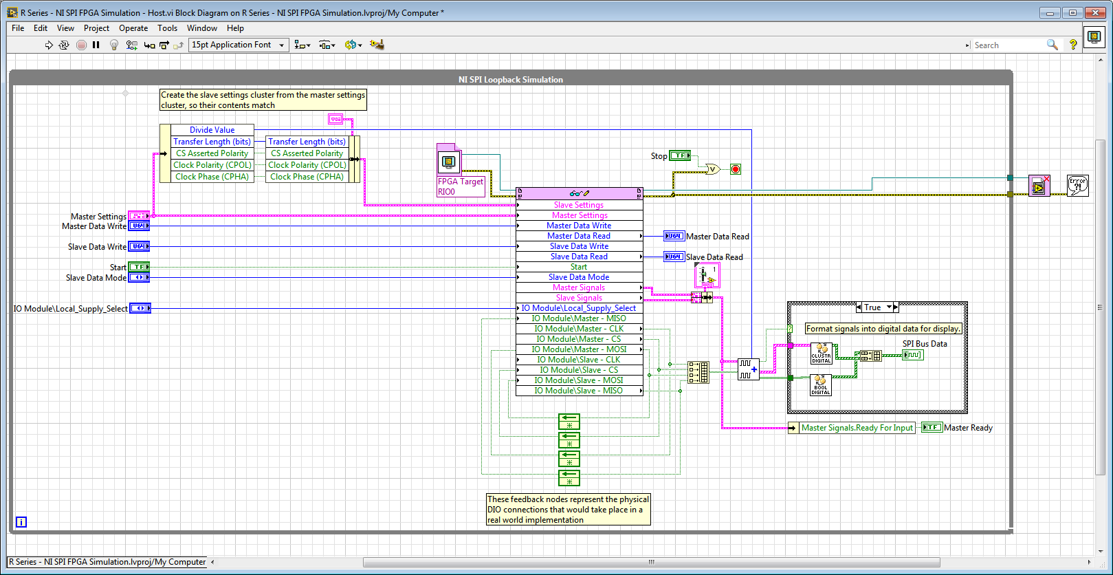
And in the Host.vi I have a node reference FPGA and wired loops of feedback accordingly:
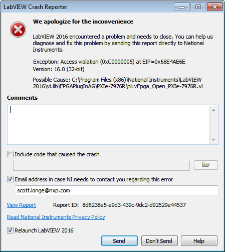
When I compile the FPGA and try to run Host.vi LabVIEW inevitably crashes with Crash Reporter below and must restart:
Does anyone know what I'm doing wrong here? My guess is that it has something to do with the CLIP/IOModule. Any help is appreciated.
Thank you
Scott
Hi Scott,.
I suspect that the problem might be related to the fact that your node open FPGA VI reference is in the while loop and trying to open a new FPGA reference at each iteration.
If you move outside of the while loop, it does not solve the crash?On channel vs port question, your logic seems reasonable to me, but I recommend to try it since this feature could depend on device.
-
Mode of scanning/FPGA for a CRIO by Veristand
Hello!
I have a small error using my CRIO 9081 use with CAN communication, here's what I did:
1. I use the CRIO with scan mode and customized it "Scan engine" and Ethercat for show my analog modules under VeriStand, it's ok
2. I use the CRIO with FPGA Scan interface (together under Labview) to detect my modules CAN, also ok
3 - then I wanted to see the CAN and analog modules, so I use this page:
http://digital.NI.com/public.nsf/allkb/0DB7FEF37C26AF85862575C400531690
And here's my problem:
with this method I am able to see the two modules with the custom device 'analytical engine and ethercat", which is really nice, BUT, impossible project VeriStand, the error message asking me to turn the chassis using FPGA, but then I lost the analog module...
So is it possible to run a project Veristand using both Scan and FPGA interface mode?
Thank you very much
Hi Vincent,.
When you tried to implement, you use the procedure described in the following document in the section use of Scan Engine and EtherCAT with NI 986 x custom device modules XNET ?
From what I remember, because you use a cRIO-9081, you will need to compile an empty bitfile for your target and place the controller in Mode FPGA hybrid mode on your chassis.
Could you post a screenshot of the error of deployment, you see?

Maybe you are looking for
-
site Web xeihapolytechnique open frequently
I have attached a picture of the URLHe claims to be an "important firefox update" but I can't find any information on the Web site at all. http://818.zb60.xeihapolytechnique.com/dbf8f149dcf4fbfa0a1fb894b0b01a54.htmlThis is the URL, nothing loads when
-
WinXP crash on connect USB-mouse
Help me please. I have to update my winxp on truth windows update - and download driver mouse tech has FOUR (I have this mouse). Windows notice me that this driver is not certified by microsoft, but I click on Yes. Now, I have a problem - when I conn
-
HHave just bought an iPad pro and wonder if anyone has one that they have already set up a wireless printer? If so little support and advice would be welcome?
-
Why do I have sound on my computer
absolutely no sound [Moved from comments]
-
Control Panel more HP Officejet Pro 8600 not lit and will not work
Control Panel more HP Officejet Pro 8600 not lit and will not work. It worked except the last 4 days. I can use certain features of the computer as a scan but can not manually use Control Panel. Nothing DOES not illuminate. The power button is on but