Boolean switch until the released counter + the number of cycles
Hi, I want to use a Boolean command button (switch release) to rely on a specific value and when obtaining this value (while pressing continuously the button) to turn on an led. If I release this Boolean button, I want to count the time until a value and then to turn off the light, like a hand for a hand detection dry.
I was thinking of using the number of cycles in a sequence of plate with a delay for the time being I want to split on a matter of true or false, but the problem is that the count of the number of cycles is continuous and not slaughter not on the specific value I want for the power button truning the seeing.
Any help?
TNX
Guy
Tags: NI Software
Similar Questions
-
I have a 2015 13-inch macbook pro Retina display. What is the best way to keep the battery in good conditions? In particular: When should I charge it? Only when the power is low)<20%) or="" anytime="" that="" i="" can?="" more="" in="" particular:="" if="" i="" keep="" it="" in="" charge="" all="" the="" time,="" will="" this="" be="" good="" or="" bad="" for="" the="" battery?="" will="" it="" reduce="" the="" number="" of="" battery="" cycles="" that="" i="" would="" otherwise="" have?="" many="">
Keep the computer plugged in whenever possible.
If you keep the computer always connected, make sure that at least twice a month
Run it on battery until battery charge level falls to about 40-50%.
Please don't completely discharge the battery. Discharge the battery completely will reduce wear and tear on the battery.
Trying to keep the number of Cycles of battery low does ' t help.
For more information:
Section: To optimize the battery life
http://support.Apple.com/en-us/HT204054
Best.
-
How do you control the number of cycles showed on the chart
How do you control the number of cycles showed on the chart? I selected a graph of scanning, and I do not see the bar vertical chart when the program runs. This is probably because I don't see the whole cycle of the periodic signal I try to display. I need to set the graph to display several cycles. Any help will be greatly appreciated.
Right-click in the list and set the required number of points in the history buffer (right-click... length of the graphic history...). Then set the x axis not autoscale and cover your historical range complete.
-
How to control the number of cycles?
I am a new user and I would like to ask a question. I use this VI (which is attached) and I want to control the number of cycles of the generated wave (sine, Triangle, saw tooth place).
How can I change the VI to do this?
Best regards
Michael
Hi FaisalF,
Looks like you're more interested in the output of a finite number of data. There is one VI example comes with LabVIEW that has this feature called tension - finished Output.vi. Then, you just create an array that will hold your 600 samples for 3 cycles of a wave of 5 Hz and entry of this table to the write function DAQmx in this VI.
-
Boolean switch until released by using a structure of the event
I use a Boolean control with mechanical action to activate the button, I want to return to the original state.
I use it in a structure of event defined to trigger a change in value. The action to push the button generates two events in the State on one and the other for when he returned to the stop State.
How can I control this to prevent a single event is triggered and the second event which is put on hold until is ignored, I want the button to return to the original state and not to execute the code twice.
Thank you
Jim
Right, I should have told latch. Do not forget to place the control button somewhere it will be read to reset the latch. It does not need to be connected to anything, just read. Sitting inside the case of the event is very good if you do not use anywhere elsewhere.
-
Log down the accumulated power on/off time and the number of cycles
Hello
I use LabVIEW to build a test program to monitor the status of the 9 switches for a long period of time, and I need to connect the following data:
How many times the switch turned on?
How long has the switch turned on?
How long the switch is off?
I built a VI, but it seems really huge... So, how I can simplify it?
Also is there any method to reduce the consumption of CPU resources? For example using the function 'to wait '?
The data stored in the table are in this format:
Cycles counter
In time
Out of time
Buffer
Switch 1
Switch 2
...
Dip-Switch 9
Thank you
David
Your method would require repeating the log F-> T and T-> F routines in each case for ever value, structure, which can be a pain if you need to make a change to this routine. Review the code that I joined. The deal structure that I will contain an instance of every routine and the line of the 2D array that it applies to is dynamic and determined by which switch has been switched. In addition, you can just the array of Boolean to the tip of needle of the index and read its value. If set to True, then this was a F-> T transition, and so wrong it is a T-> transition F. Another thing, you had connected the stop button to a terminal of the while loop stop. When you have a structure of the event he's right there waiting for one, it's events to trigger it in action. There was no event stop Stop button never actually stopped the VI. So I added back a change of value of Stop event if it would work. Let me know if that makes sense.
-
How to control the number of cycles in the shape of triangle
Hello
I'm quite new Labview programming and find a hard time to code a simple program. If anyone can help me find a way to control the no. cycles of a triangle pattern.ie, if a key is pressed the code should send an individual right. wave form when it is in place the button should switch to its original state. I enclose the code that I've used to working on. The material used are NI 6013 and NI6723, as well as two BNC-2110 as input and output.
Thank you best regards &,.
George
Hello
first of all, if you want to have an application like this, a simple while loop will not suffice. You will need to use a state machine or producer-consumer model. You read about them here, you have also some models and examples in LabVIEW.
Another thing is that the production finished, it would be preferable to use the sample mode "Finished samples" (in the DAQmx Timing.vi configuration).
-
Why is the number of cycles (ms) does not follow Dataflow?
I learned basic examples of stream of Labview as several Add, Subtract... blocks to proceed to execution at the same time and we can visually see the stream in execution to highlight mode.
In this example, I would expect Ms. County to charge its value at the moment that the first image is running. However, in reality, Ms. County will charge only its value to the right terminal after search replace chain finishes (time consuming). This means that the lag is zero!
Note that the integer constant load the terminal at the time where the start of the frame which is correct (unlike the County, ms)

-
Number of cycles in the target FPGA VI
Hello to everyone.
I'm working on a project where I use sb RIO 9636. I subtract a number of past and present of the encoder pulses. Here, I have attached VI that I use as target VI. When I use simulated I/O lets say that the program works correctly. When I compile VI on sbRIO I noticed that the LED indicator named x = y? never flashes (even if she flashes simulation). Also, when I put indicaton on the number of cycles of control, counting starts from a few very very valuable.
Could someone help me?
Thanks in advance.
Hi Chupka993,
I suspect that part of the behavior of the that you describe, is that when you change the clock of the loop, you change the speed at which the loop works. As GerdW said, this loop timer setting gives your code a rate at which it should run. For example, defining 1ms means that your code inside this loop executes once per millisecond, or 1000 Hz. ticks would work similarly, but I think the timescale ticks of the FPGA clock which is generally 40 MHz on our devices.
When you have the timer set to 1 millisecond loop, the code in the loop executes 1,000 times per second, and your iteration count would be 1000 times before update output, which means that your code runs a full 1000 iterations once per second. If you change the clock of the loop of 2 milliseconds, the loop will run 500 times a second sense that your 1000 iterations would take 2 seconds to run. I think that the behavior you're seeing is because the iterations are produce faster that you intend.
You need to understand exactly how much time it should take your loop to run 1000 times and then set the timer loop to the appropriate value to achieve this goal.
-
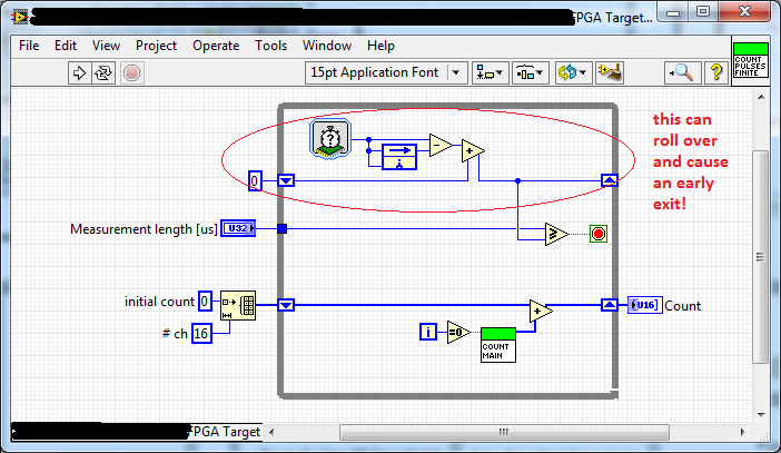
How to manage the turnover in number of cycles of FPGA output?
I wrote a little VI that counts ticks on a set of lines of DI for a period of time. It uses the number of cycles of VI to determine how much time has passed since he started running. The output of this VI is a U32, and subtraction function looks like it going to saturate to '0' if the number of cycles longer rolls. How can I handle this situation to prevent the VI to leave earlier?
Integer arithmetic must manage calculation rolling correctly (for example if your value is a U8 and you do 3-250, you should get 9). I guess (although I never checked) it works even in the FPGA. You can do a simple check yourself with explicit code. It would be nothing less than a complete cycle of safe, so it depends how much time it takes. If it is ms, it would take about 50 days. In your case, it seems that you have configured the service to be in us, so it would be somewhere more than an hour. If that's not enough, then you can maintain the real value in a U64 and then take the number of us that passing in each iteration and that adds to the U64.
-
Number of cycles Express VI outputs '0' on target with simulated FPGA of e/s
When I set my target to "Run VI on it development with simulated i/o", the number of cycles to screw all the outputs ' 0 whenever they perform. How can I do a count up (in the case of "ticks") or a timestamp that is appropriate (in the case of "ms") the output?
In fact it does not work as expected. I apologize. When in mode [ms] he ran if slowly as my test that bolt looked like they were defective and I did not notice the value incrmenting when I probed it. I changed the test to use the [ms] instance when running on the FPGA and the [ticks] instance during execution with simulated IO. This looks like it gives 1 tick every "" millisecond"simulated" when simulating and now operate my well tests.
Thank you very much for the help. Sorry again for the false report.
-
How to avoid overflowing number of cycles?
Hello.
I was warned for a long time on the use of number of cycles as basis for some time structure timeout, because the number of cycles is beyond every 49 days or more. Since then, I had a bad taste in my mouth about its use, and I wonder what I can do about it. I tried a bit with the comparison of the value of the number of cycles with the time and subtracting the value of timeout to the value of the number of cycles if this would cause a number of cycles to overflow. But the code happens to be more than a bit messy and not very flexible. Just see the attached VI. Does anyone have a good solution on how to get around this problem?
I found this blog post from a guy who has made a conversion from 32 to 64 bit VI, and it seems to be just to the top of my ally. But I was not able to reproduce because I recognize not all symbols (especially the small round one connected to the structure of matter at the far left).
This wanring should be interpreted such that you should not expect the value to be always on the rise.
The difference between the two ms tick counties will work even during the maxi over because this is how the calculation works for a U32. So if you subtract the beginning of the current, you can always compare the difference with the other to check if a certain amout of time spent.
Ben
-
How to make a turn of the indicator on after 15 seconds using the number of cycles?
Oops
-
In tools, under the protection of personal information, I was able to set the number of days during which the browser history... Very handy when you need to keep a record of sites visited. Now in Firefox4 I have "Remember history" option. How will I know how the newspaper story is saved for the moment?
In Firefox 4 you can no longer set the number of days of historic preservation. The method used by Firefox to store history has changed, for more details on the changes, see http://blog.bonardo.net/2010/01/20/places-got-async-expiration
-
Go until the released function has changed?
Then, I changed my laptop and to reinstall the LabVIEW and all the rest to continue working, does not have a physical medium on hand, so I download lv of the site and didn't know OR now shoehorns lv 2016 as de facto download, if you want to update or not. I tend to wait a few months to move the software precisely because of such problems.
Whatever it is, I do a simple record xml base VI to check the feasibility and add a Boolean button to trigger the adding item to a table that will later be stored in format xml, nothing complicated. I have change the mechanical action of "switch release" because I expected the old feature which, if I'm wrong, was:
-User (me) press the button, probably holding
-Button lights up, depressed, but continues to send a fake
-L' user releases the button
-A single, 1-time real impulse is sent to all what
Now, however, I believe that by tapping lightly on the button sends about 1, 4 k elements in the table, so it seems that the feature has been changed to "send true until the user releases the button. After my rants, could someone please tell me if this is a bug or the destination behavior? Where can I find the old 'switch release' Boolean?
I think you are looking for the latch releasing action.
http://zone.NI.com/reference/en-XX/help/371361M-01/lvconcepts/boolean_controls_and_indicators/
Edit: to answer your question about is it planned? I would say yes, because the value is set to true and continues to be true until you release.
Maybe you are looking for
-
Problem with GPS in very remote locations...
Hello I recently went to some remote areas of Western Australia. My phone is an old 4S running 9.3.5 In these remote areas, I had either no reception iphone mobile, or the receipt of another carrier (to what I had) so all the I could get is SOS capac
-
No longer get a dialog box when you save a bookmark
That's all. Unable to save a bookmark.
-
Problem DVD double layer on satellite A210-15
HelloI have a satellite A210-15 and cannot read dvd dual layer, I a reading of dvd double layer and then nothing, the dvd player don't know the dvd.My sister has the same laptop that me and him it's ok.Can you help me.
-
Satellite A665 - 12K - what battery is compatible?
_ * Wrote the following text has been translated by machine translation.*_ Hi, I have a notebook * Toshiba Satellite A665 - 12 K *.Today, * utility Toshiba PC [email protected] monitor * displays a message indicating that the battery is in p
-
Satellite L300D-13s on flights long-haul
I have a Toshiba laptop Satellite L300D-13 s SYSTEM UNIT. Is the Li - ion battery. Model number PA3534U 1BRS. 6 CELLS. As I am on a trip to Australia next week on a flight that lasted 21 hours, is there something I can do or buy to be able to use my