Break-in LED FPGA
Hi, in the attachment you will find a VI that allows to create several LEDs running in any of 20 places. The user can increase the number of running LEDs, i.e. the distance between the LEDs running and duration, they are on. Which works very well.
My boss wants that I program the same 'thing' in FPGA in LabView! I don't know what exactly would be the difference of my program at this time. Can someone help me?
Thorsten salvation!
I'm glad to hear that you managed to use your cRIO.
I think that your algorithm can be greatly simplified by using a simple bit shift function. That would also benefit the implementation on FPGA, given that this function will not consume a lot of resources on the FPGA. Probably, the VI in the attachment does not meet all your requirements and needs a few adjustments runs correctly on the FPGA, but I think he should give a good idea about the functioning of the algorithm.
Kind regards
Georg
Tags: NI Software
Similar Questions
-
myRIO - problems when using onboard LED
Hello
for some reason, I can't not lit on board LED. I try to use a block of myRIO-> default-> LED FPGA personality. Block properties, I chose LED0. Then I create a Boolean constant and the value is FALSE. After that I wire to LED0 port. When I run the application, the LED is not lit. Previously mentioned block is inside a loop timed, who works for sure.
Jussi-Pekka
-
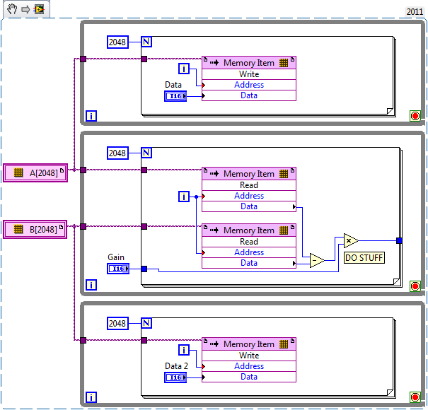
PXI FPGA NI7831R Subvi nirviExtendedMemory.vi LV2011
With LabVIEW 7.1 projects, I had been using a Subvi memory, called nirviExtendedMemory.vi - it works like a memory "non-volatile". The Subvi is called by a 16x128block.vi. The subvis work together with LabVIEW 2011 on the host, but it breaks a LabVIEW FPGA 2011 because project as the "sub - VI 16x128block Subvi is not executable.
I'm new to LabVIEW 2011 - may it be resolved in the project FPGA configuration?
Thank you
John
Hi John,.
Can you give a little more information about the feature you are trying to reach? Would it not possible to post these Subvi?
Perhaps what you are looking for is the memory block. Try right-clicking on your FPGA target and selecting new > memory. Take a look at the "Memory check" section of this article.
Best,
-
I need to change a FPGA.vi that has already been deployed on a cRIO and runs at startup.
What is the best way to change the program without changing its function. I just need to say if the cRIO is online or not - of a host.vi with a FPGA reference (I tried to use the LED FPGA as an on/off control switch) without success). I have to stop or suspend the operation of the existing FPGA.vi to do this, or there at - it an easier way? Can I use the same FPGA in another window for project? I'm running 2009 LV a NOR-9012 controller with Windows XP Pro with a chassis OR-9112.
-
using slots chassis for general use cRIO
Hello
I have cRIO-9004 and cRIO-9103 Chassis, labview 2011...
AFAIK, the cRIO chassis controls its slots if it present any module or not... If someone detect read EEPROM and so on...
But how can I control the slots on the frame cRIO for my own general use without any module...
When I create projects, it shows me just like I/O chassis
* chassis temperature
* LED FPGA
* Scan clock
* Sleep
* the system reset
I couldn't write anything of chassis slots and see to the oscilloscope screen, (for example: using a digital or analog output)...
Didier...
Try to follow the steps, you will create a new module. As in this example, but skip the part of the circuit.
-
How to transfer files from damaged computer (intact HDD) W7 to new computer with W7?
Computer fell, breaking the LED screen. Failed to start. Buy the new computer, poreferably with OS W7. How can I transfer files from old computer to the new without losing data? Should I change to W8, rather than transfer again to W7?
Monday, December 17, 2012, 15:50:02 + 0000, Ron BMD wrote:
Computer fell, breaking the LED screen. Failed to start. Buy the new computer, poreferably with OS W7. How can I transfer files from old computer to the new without losing data?
If you have deleted from the computer, there is a good chance that the hard drive
has been destroyed, and the files are gone.Should I change to W8, rather than transfer again to W7?
Your choice entirely.
- http://answers.microsoft.com/message/f940a881-cafd-4a68-8c4d-ac2c26896535
Ken Blake, Microsoft MVP
-
Momentary button to turn on/off LED - LabVIEW FPGA
I started to learn something with the hardware (cRio-starter kit). I want to implement what is called 'memory' in the engine control is when I press a button (PS1), the LED (LED 1) will change its State and stay until you press PB1. I tried to apply it, but failed completely. It must be done with a registry but I just couldn't keep it from Flash.
Hi muahang,
use a shift register to maintain the previous state of the button. Compare the current state of the button with his previous. When you detect a rising edge reverse you the Boolean value of a second register shift. Write the Boolean value of the second register to offset your led...

Key words: boolean, from edge detection, register shift
-
BlackBerry Smartphones Dead "BOLD" / blinking of LED 1 break 3 (10111)
This morning I removed my "BOLD" on the charger and the wonder why "BOLD" was turned off.
After trying to switch it on, the light starts flashing time "a pause of three."
After a battery pull no change in behavior. Also without the battery, but connected via USB to a pc, the led "BOLD" starts flashing.
/Nojvm JL Commander or the charger does not change. The Berry was not recognized by the pc.
Welcomes Birger
Thank you
but I follow the JL_cmder until I post my question here, and yes I have try several times.
But Vista and / or JL_Cmder does not recognize the device.Is there information on the led Code?
I receive today my provider a new replacement "BOLD", then I can mark this as "resolved".
-
LabVIEW FPGA SPI accident - SPI OR IP address for example - R series OR
Hello
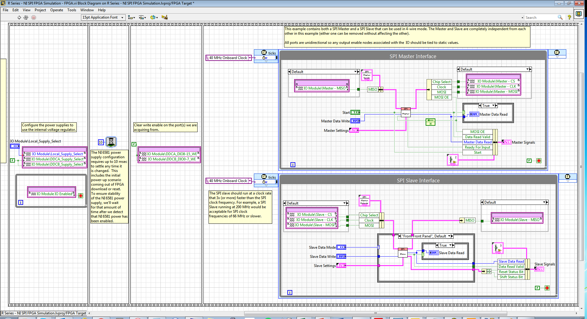
I am trying to run the series R - sample project NI SPI FPGA Simulation.lvproj that comes with the SPI IP OR on a real FlexRIO FPGA SMU-7976R target with an attached digital adaptation NI 6581 B Module. The example is for a PCIe-7841R but I wore during my target FPGA, follow these steps and made additional changes to try to make it work with my set-up. I learned that FlexRIO FAMs CLIPs do not work with nodes in office had so I know I can't simulate the project originally planned so I will try to use FPGA to e/s node host side (open FPGA vi reference) to implement the actual hardware.
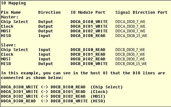
My first question concerns my configuration of the adapter module e/s and selection. I added the IO Module (NI 6581 B: NI 6581 B channel) for my project and selected the channels as shown in the table below. I have a real physical hardware connection as described below using two NI SHC68-C68-D4 cables and a break-out Board.
I changed the names as well:
I selected these DIO channels because I wanted the DDCA connector to be the master and the DDCB connector to be the slave. In addition, in this CLIP every eight channels of i/o has a write enable signal. I have not used the Port configuration because I needed 4 available DIO channels and I saw DIO0-3. Is my logic of selection of channel vs correct Port here?
Following the same strategy that examples FlexRIO/NI6581B, I changed the FPGA.vi to include initialization outside of timed loops:
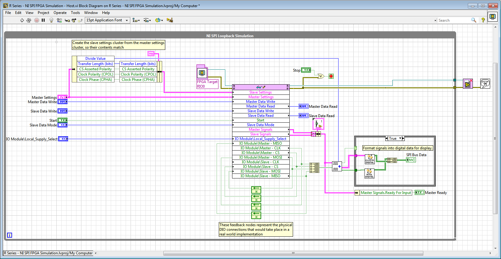
And in the Host.vi I have a node reference FPGA and wired loops of feedback accordingly:
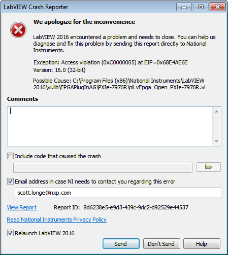
When I compile the FPGA and try to run Host.vi LabVIEW inevitably crashes with Crash Reporter below and must restart:
Does anyone know what I'm doing wrong here? My guess is that it has something to do with the CLIP/IOModule. Any help is appreciated.
Thank you
Scott
Hi Scott,.
I suspect that the problem might be related to the fact that your node open FPGA VI reference is in the while loop and trying to open a new FPGA reference at each iteration.
If you move outside of the while loop, it does not solve the crash?On channel vs port question, your logic seems reasonable to me, but I recommend to try it since this feature could depend on device.
-
24 v digital signal of the event from the host to the fpga power on/off
Hello forums or
Sheet material
cRIO-9074
module or 9472 digital module 24 V output c series
To expand on the topic described,
I want to be able send a trigger to alarm the fpga digital 9472 out that lasts 30 seconds using the operating system time real clock time on the host computer
The way I approached this problem is that
In the loop where the event occurs, if the event trigger is defined then the fgv has a time stamp when the event occurred is sent.
In the loop that communicates with the control of fpga, I write to the control based on the condition that the difference of the current time checked and fgv time is 30 seconds or less, then it will send the value true, otherwise send fake and wait for the next occurrence of the event.
The main problem after implementation of this is that 9472 led does not turn off when the false value is sent to it.
cordially Mzamanstl
Timer Keeper SD is a FGV so that it is written for her, once the event occurs
So if the event occurs so timestamp is stored and then the difference of the timestamp result is<30>
then a true value will be sent to the module of 9472
So basically I want the light and I want to do the 24 v output for 30 seconds then turn off and wait for the next occurrence
I think the method that I test it with is not very good, because I realize other factors that may contribute to this problem, so I think I found another way to test
and I will try it but its will take time.
cordially Mzamanstl
-
Network shared Variable breaks rtexe
I have a cRIO-9063 which I want to use for the control (PWM digital output for pumps signals) and measurement (temperature and voltage) of a system. In the ideal configuration the cRIO would be able to take measures and rebroadcast to a PC for monitoring and logging. The PC must be also able to change the digital output PWM on the cRIO lines. The cRIO should be able to continue to operate when the PC is not available. To do this, I use Scan interface for data acquisition and shared variables (single editor, no RT FIFO) hosted on the cRIO for network communication.
I have developed the code for the target cRIO as well as my host PC meets my criteria. However, this code only works in development mode. When I try to build and deploy a rtexe on the cRIO, it does not work. I reinforced to the back and made a simple LED flashing user vi, ensure what I create and deploy properly. Slowly adding things to this flashing vi, I discovered it's shared network variables that break the vi once it is integrated into a rtexe.
After flipping through other-related posts, I'll include the following:
-There is no object on the remote VI front panel. Simply add a variable node shared is enough to break the vi (when it is deployed).
-J' tried including my shared variable library in support of the construction directory, but what I saw there is not copied during construction or deployment. I manually copied the library to the /home/lvuser/natinst/bin/data / directory on the cRIO, then used an invoke node to deploy the cRIO variables when the software starts first. Even when you include a delay of 10 seconds after the invoke node, it did not work, just a mistake of 1043 at "the method or property is not supported in this version of LabVIEW."
-NSV is referenced as absolute
Some details of my configuration:
LabVIEW 2015
cRIO 15.0
NOR-RIO 15.0
Communication via ethernet, static IP
Any help would be GREATLY appreciated. I suspect that I forget a few minor step or detail, otherwise am poorly understand exactly how and when shared network variables are deployed.
I found shared to not be worthwhile over the years network variables.
The RT EXE is not able to use the library to deploy to deploy the shared Variables. See Help topic: http://zone.ni.com/reference/en-XX/help/371361M-01/lvprop/app_libdeploy_library/
In general, SV are deployed once the project and they persist through reboots of the RT system. In general, you should have a startup routine that checks the shared variables and expected for there to be without error on a node of the OAS and then move on to the rest of the program, defining the commissioning of values and check that they spread in the engine of the Variable is a typical method.
See here for more information on the deployment of a variable in an application of the RT. http://digital.NI.com/public.nsf/allkb/990508969805A7C086257619007189E7
The section deployment of Variables shared in a real-time (RT) target running Headlessly is downstairs. Because you are connected to an HMI PC, you should be able to use the library to deploy feature of the PC code targeting the cRIO.
Usually, it's a faster, more scalable solution to replace your shared network Variables with a stream of network dedicated to the HMI and another for HMI - RT EXE commands. You can send complex structures such as a cluster or even define the message as a cluster of enum and variant type to be able to use the Enum to convert the variant correctly according to the Enum value.
-
Hey there,
attempts to establish a connection to a Julabo F33 ME cryostat. I'm using cRIO9074 and module: NI 9870.
I got a model (FPGA.vi, RT.vi) of a colleague who runs his Circulator julabo on a similar system. Somehow, I can't return all of the controls on the device or get information.
RT.vi: I've amended the vi to send a command (String: in_sp_00) to the julabo (Mod1/Port1). I send you only empty strings to other ports because I just want to test one. It must respond to a temperature of these, but I can't get an answer.
I double checked the connections and settings for the COM port...
Find the screw in the attachment.
I hope someone can find mistakes.
Kind regards.
You can also include 'writing sub - VI'?
A common mistake with the serial communication is to forget to include the character of termination or line break after sending a string. The cooler waiting orders will end with a carriage return, linefeed, or both? If so, you must include in the chain that you send. Right click on the command string constant, choose "display codes"------"" and add to a carriage return ' \r' or '\n' for a line of flow at the end (or press just press enter at the end of the string constant to add a new line, that often works too).
-
Embedded FPGA vi - network shared variable not updated
Hello
I work with an ethernet RIO 9149 of data acquisition. I use a hybrid programming mode.
I have a very simple FPGA VI that I downloaded on the flash memory. I used the indicator led to show my VI runs once the power of the RIO. Everything is fine, except that my shared network variables are not updated in the DSM ("no known values" displayed). However when I run the FPGA VI of my laptop, only once then stop and close (with 'interactive execution'), then my shared variables are updated in the DSM.
Any ideas why is this and how do I get the RIO update automatically shared variables without having to run the VI once?
Thank you very much.
Hello
I did a few tests and research and discovered that it doesn't seem to be possible. It is important to note the difference between Network-Published static (NSPV) and Variables of e/s of Network-Published.
The other are "user defined variable I/O" to communicate between FPGA and RT (RT absent on chassis Ethernet as the NI 9149) host. If these variables are checked to be published-network (in properties). They are accessible by VI running on the hosts of the same LabVIEW project, so you need to run a VI to access, as you mention. This is explained on the next page, Variable IO data custom FPGA of e/s (real-time Module or Module FPGA):
https://zone.NI.com/reference/en-XX/help/371361H-01/lvioscanhelp/io_vars/#user_IOV
I did find a way without a host (host RT or Windows PC) running a VI. If you have a cRIO with RT and NPSV host in the RT VI it is possible.
-
Number of cycles in the target FPGA VI
Hello to everyone.
I'm working on a project where I use sb RIO 9636. I subtract a number of past and present of the encoder pulses. Here, I have attached VI that I use as target VI. When I use simulated I/O lets say that the program works correctly. When I compile VI on sbRIO I noticed that the LED indicator named x = y? never flashes (even if she flashes simulation). Also, when I put indicaton on the number of cycles of control, counting starts from a few very very valuable.
Could someone help me?
Thanks in advance.
Hi Chupka993,
I suspect that part of the behavior of the that you describe, is that when you change the clock of the loop, you change the speed at which the loop works. As GerdW said, this loop timer setting gives your code a rate at which it should run. For example, defining 1ms means that your code inside this loop executes once per millisecond, or 1000 Hz. ticks would work similarly, but I think the timescale ticks of the FPGA clock which is generally 40 MHz on our devices.
When you have the timer set to 1 millisecond loop, the code in the loop executes 1,000 times per second, and your iteration count would be 1000 times before update output, which means that your code runs a full 1000 iterations once per second. If you change the clock of the loop of 2 milliseconds, the loop will run 500 times a second sense that your 1000 iterations would take 2 seconds to run. I think that the behavior you're seeing is because the iterations are produce faster that you intend.
You need to understand exactly how much time it should take your loop to run 1000 times and then set the timer loop to the appropriate value to achieve this goal.
-
tables of fixed size in FPGA compilation error - how to implement a waveform control in an FPGA?
Hello
After being stuck for two days, please let me briefly describe my project and the problem:
I want to use the cRIO FPGA for iterative control of waveforms. I want to capture a full period of the waveform, subtracting a reference waveform period and apply control algorithms on this. Subsequently the new period of correction must be sent again for the output module OR. If it does not work, the captured waveform will look like the one reference after several iterations.
I am planing to create an array of size fixed for the capture and the reference waveform (each around 2,000 items for a given period). I use so 2 paintings of each elements of 2000. I use the function 'replace the subset of table' to update each element captured in the loop sampling and a feedback for each table node to keep in memory (I also tried shift registers, but then the berries do not have a fixed size any more and I can't start the compilation process).
If I try to compile the FPGA vi, I get the following error:
Details:
ERROR ortability:3 - Xilinx this application runs out of memory or met a memory conflict. Use of current memory is 4167696 KB. You can try to increase physical or virtual memory of your system. If you are using a Win32 system, you can increase your application from 2 GB to 3 GB memory using the 3 G switch in your boot.ini file. For more information, please visit Xilinx answer Record #14932. For technical support on this issue, you can open a WebCase with this project attached to http://www.xilinx.com/support.
"Synthesize - XST" process failedBefore I added berries to my code I could compile the FPGA without problems. So, it seems that the tables are too big for the FPGA. :-(
Therefore, I would like to ask if there is perhaps a better method to implement my problem in LabVIEW FPGA? How could avoid the tables to save my waveforms on a period?
Thanks a lot for your help in advance.
Best regards
Andreas
Unfortunately, the LabVIEW FPGA compiler cannot deduct stores shipped from berries (yet). When you create these two large paintings, you are creating essentially several registers very, very large. Just by looking at your picture, I guess that there are at least 4 copies of each of the tables.
You want to use LabVIEW FPGA memories instead. You can create memories outside the loop and then read/write them where you are currently referencing the berries. The only change that you really need to do is to break down your treatment in scalar operations. I have attached a simplified version of your plan, I hope it helps. Let us know if you have any other questions.

Maybe you are looking for
-
Unable to format hard drive for Windows
Hello, I need your help here! You receive the same error message saying: "Windows is unable to complete the format" when you try to format an external hard drive on your computer? Honestly, the hard drive of my dell computer recently asked just to ge
-
HP compaq dc7900 cmt: need help to identify certain hardware in some tech.
Good, good morning/afternoon.Ive had trouble understanding this old pc that I found laying around. I decided it might be fun to try to update as a challenge for a bit of fun. However after getting the open pc intel core 2 duo cpu is not the usual dev
-
Questions about the replacement of a power supply for a P7-1235
I decided to do an update on my Pavilion P7-1235. I put in a graphics card and put in power level. After doing some research on this forum and others I know well enough that I need. The only question I have is about the food. I don't know what the or
-
Satellite A200: How to capture video from your camcorder
I bought a JVC GR-D50EK camcorder, about 4 years ago. So far I have never tried capture video on the computer, but I need to do now and I can't seem to do. I have a Toshiba Sat A200 which I bought 2 weeks ago and I tried to use Ulead DVD MovieFactory
-
How to get the beats audio works on windows 7
Envy just downloaded windows 7 on my hp dv7 and my audio beats no longer works. Is there a driver I need to download to correct the problem? Or is there a configuration I need to do?