24 v digital signal of the event from the host to the fpga power on/off
Hello forums or
Sheet material
cRIO-9074
module or 9472 digital module 24 V output c series
To expand on the topic described,
I want to be able send a trigger to alarm the fpga digital 9472 out that lasts 30 seconds using the operating system time real clock time on the host computer
The way I approached this problem is that
In the loop where the event occurs, if the event trigger is defined then the fgv has a time stamp when the event occurred is sent.
In the loop that communicates with the control of fpga, I write to the control based on the condition that the difference of the current time checked and fgv time is 30 seconds or less, then it will send the value true, otherwise send fake and wait for the next occurrence of the event.
The main problem after implementation of this is that 9472 led does not turn off when the false value is sent to it.
cordially Mzamanstl
Timer Keeper SD is a FGV so that it is written for her, once the event occurs
So if the event occurs so timestamp is stored and then the difference of the timestamp result is<30>
then a true value will be sent to the module of 9472
So basically I want the light and I want to do the 24 v output for 30 seconds then turn off and wait for the next occurrence
I think the method that I test it with is not very good, because I realize other factors that may contribute to this problem, so I think I found another way to test
and I will try it but its will take time.
cordially Mzamanstl
Tags: NI Hardware
Similar Questions
-
digital signals at the same time 16
Hello
I used a PXI-6254 adapter connected to the scb-68 and I try the digital output signal 16 on port 0 at the same time, so I chose to use the connector 1 port 0 line 8-23 but I can't outpul all the signal, he works for line 8-15, but for the rest, 16-23 does not work and I do not know the reason.i join 6254 board configuration and vi that I use
Hello bobogool,
I have taken a look at your code and noticed you write only FFFF, who would write only the first 16 lines, 0-15. Did you follow the first 8 lines of activity? If they work, I recommend that you add 8 extra bits, up to 23.
-
Log down the accumulated power on/off time and the number of cycles
Hello
I use LabVIEW to build a test program to monitor the status of the 9 switches for a long period of time, and I need to connect the following data:
How many times the switch turned on?
How long has the switch turned on?
How long the switch is off?
I built a VI, but it seems really huge... So, how I can simplify it?
Also is there any method to reduce the consumption of CPU resources? For example using the function 'to wait '?
The data stored in the table are in this format:
Cycles counter
In time
Out of time
Buffer
Switch 1
Switch 2
...
Dip-Switch 9
Thank you
David
Your method would require repeating the log F-> T and T-> F routines in each case for ever value, structure, which can be a pain if you need to make a change to this routine. Review the code that I joined. The deal structure that I will contain an instance of every routine and the line of the 2D array that it applies to is dynamic and determined by which switch has been switched. In addition, you can just the array of Boolean to the tip of needle of the index and read its value. If set to True, then this was a F-> T transition, and so wrong it is a T-> transition F. Another thing, you had connected the stop button to a terminal of the while loop stop. When you have a structure of the event he's right there waiting for one, it's events to trigger it in action. There was no event stop Stop button never actually stopped the VI. So I added back a change of value of Stop event if it would work. Let me know if that makes sense.
-
Hi, I had a SCB-68 DAQ card. I would like to set up a high voltage ON OFF LabView options to be able to remote, turn on or turn off the high voltage to power cold cathode (the manual is attached, see pp. 24 and 25), but honestly, I don't know how to do it. Can anyone give me a tip please?
NOR has the 6008 and for students, myDAQ. Other suppliers might be. Depends on what you might want to use.
-
PCI6120-acquire an analogue signal on each edge of a digital signal
Hello
I have the card PCI-6120 and Labview 7.1.
I have a digital signal of the encoder. Am interested in buying an analog voltage on each rising edge of the digital signal. In addition, I have another digital signal (index) between which I wish to make the acquisition.
I tried several options. But I can't get on the digital dashboard via the hardware. Please help urgently. Alternative, I migrated to the acquisitions acquisition high speed analog and two digital channels and deteting change in software programming and then find the analog voltage. Which is heavy and inefficient.
Kindly guide correct programming technique.
Concerning
Marie-Hélène
Hi, Maud.
Thanks for the update and I hope that your well today.
Sorry for the delay but it was the Easter holidays!
Thank you for your congratulations.
I put your sampling frequency at the maximum rate of the clock source (encoder). The DAQmx driver uses the sampling frequency (and the number of samples per channel) information to perform various calculations and set sizes for the buffer.
If you set it too high, nothing will happen-guests still just on each edge of the unit receive. If you set it too low, your stamp could be too small and you may lose data.
Hope this helps,
-
I would like to create a digital waveform as instructions for a stepper motor. The task is to get the motor shaft turn at variable speed within each rotation. I tried to do this by dividing the rotation in a number of blocks that each run at a different speed, thus forming the concatenated rotation profile.
The problem is that then the concatenation of the digital signals with the Append VI, I am unable to remember the different frequencies of the individual wave since the Append VI seem to require a constant interval between two pulses. Is it possible to explicitly concatenate accurate digital waveforms to form the desired profile?
Try again with the modified VI.
-
CPU limitation with the new power supply
Hello
I have a W510 with 135W POWER supply. Or to be more precise: A 6.75 @ 20V.
I work at two locations, so I bought a generic 150W PSU with an adapter to mount the Thinkpad. The PSU is labeled 7. 5A @ 20V, so there should be no problems running the laptop.
Yet, when starting, I get the "this power supply is too low for something something something battery charge" and strangled my i7 at 1.2 GHz, and not the 3.06 there are usually.
If I boot from the battery and connect the connector of the power supply after Windows is in place, it works at full speed. And to charge the battery very well. Then of course, there is nothing wrong with the juice from the PSU.
Thus, I suspect that the BIOS does something stupid. Can I override this somehow?
Friendly,.
A guy
Maybe what the ThinkPad does not does not correctly detect the generic adapter. The central axis of the generic adapter does not give the right signal to the laptop power management firmware.
Check in the ThinkVantage power manager what to say under the generic adapter 150 watts? He said 90 watts?
-
time extraction of the digital signal
Hello
If I have digital signals from optical barriers and to extract the time (for a body that passes these 2 obstacles) how can I retrieve this day there using Labview.
THX
I have chata,
Thanks for the answer, and I hope that your well.
Here's an example I've done for a client, eager to discover the time of a flat section of its waveform.
In your case, you must make a detection of pic on both codes, then less locations and a few x with the number of the sample to get the time.
Let me know what you think.
Kind regards
James.
PS Sorry code is a bit hasty.
-
When you try to import video files in Movie Maker I get the message; M2U00017. MPG could not be imported. An interface has too many methods to fire events from
-What this means and how do I fix it so I can import video files to edit?
When you try to import video files in Movie Maker I get the message; M2U00017. MPG could not be imported. An interface has too many methods to fire events from
-What this means and how do I fix it so I can import video files to edit?
=======================================
Movie Maker has problems with the .mpg files... best bet would be
to convert the .mpg files before importing the .wmv format.Several formats are apparently compatible with
Movie Maker, but the most reliable choices are:Photos - bmp
Video - wmv or dv - avi
Music - wma, wav, .wmvSee the following article:
Movie Maker 2 - Import MPEG files
http://www.Papajohn.org/mm2-importing-video-MPEG2.htmlThe following freeware can convert:
(FWIW... it's always a good idea to create a system)
Restore point before installing software or updates)Format Factory
http://www.pcfreetime.com/
(FWIW... you can uncheck
all the boxes on the last screen)After downloading and installing Format Factory...
Open the program and choose an output folder...
(this is where you will find your files when they are
converted)Drag and drop your video clips on the main screen...
Select "At?" / OK...
(the? is the format of your choice)Click on... Beginning... in the toolbar...
That should do it...
Good luck...
John Inzer - MS - MVP - digital media experience
-
The "day starts at:" options correctly offer options of "midnight" through time "am" to "noon". Thus the "day ends at:" should have options starting with "midi" and moments of "pm" to "midnight", but instead, they are all time 'am '.
And alerts for an event from 14:00 activate at the right time, but it's at 02:00. Maybe it's a consequence of the above.
???

-
iMovie 10 - how to merge the events from different sources?
I libraries iMovie on 2 hard drives and in iMovie on two iMacs files both running iMovie 10.1.1
How can I copy all my events on a single hard drive but leave the events and projects on both iMacs?
The projects will move at the same time or how can I move them as well?
Thanks for any help possible!
You can copy events from one library to another of in iMovie. See:
http://help.Apple.com/iMovie/Mac/10.1/#/mov3fa25bae7
For more details.
Geoff.
-
frequency of the digital signal 6009
Hello, how to generate the digital signal with frequency 50 Hz using NI USB-6009?
You can take a look at this:
Can I use a generation of impulses with the counters on the USB-6008/6009 case?
-
Could someone tell me how to convert the digital signals in table 1 d of digital waveforms
I use 9474 for drving an engine. for that I have uses 2 ports - to activate and another for running. These signals in the form of Boolean values. I am to convert these signals to a table and since iam doing a digital waveform. but when iam connecting these to the module 9474, it show an error "source is a digital waveform and sink is 1-d array of digital waveform... any body can help in these issueee please...»
Pop - up on the thread and choose Insert...
Build the table.
Ben
-
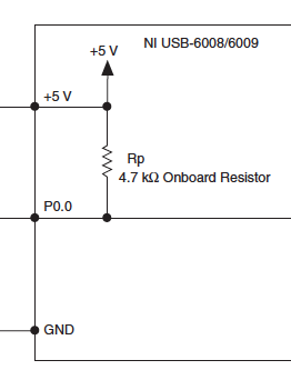
6008 USB shows the digital signal with nothing plugged
So I really hope that's not too bad, I guess it is.
I had problems reading of my digital USB 6008 entry this morning. Everything worked very well last night. Now all digital lines on the device to read a signal if it is has that anything connected to them or not. When I run the DAQ Assistant and test line, it shows a signal to each line. Then I did the joint VI (which should do the same) and it shows a constant signal in each line also. And I have nothing connected to the unit. Should reset somehow, or it is broken? Or am I just missing something?
nckeeley,
Look at pages 21 and 22 of the User Guide Ni USB-6008/6009 and specifications. Digital lines have a traction 4.7 kilohm place resistance to + 5 V. It will be a line of input opne look (and be) high.
Lynn
-
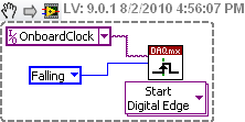
How to generate a digital signal on a negative slope of the clock?
Hello
I need to get out a finished length of the Digital pulse which will begin on request to the negative of the clock slope import (or export).
I try to get the clock, exported or imported, but in any case, I can trigger output signal on the negative slope.
What is the trick?
Thank you
Pawel
What camera you use to build your digital signal. What is the source of the clock? You can attach your vi? Normally, there is a function of data acquisition for configure the trigger where you choose the source of the trigger and the trigger slope (rising or falling), should be declining to a negative slope.

Maybe you are looking for
-
Equium A210 - replacing the CMOS battery possible?
My Toshiba Satellite A210 - 1 4 seems to have a CMOS battery problem because it does not keep the BIOS settings. I bought a replacement battery and a/c mains adapter to remove the a/c power problems but the POST beaps and CMOS keeps a checksum error
-
Address book contacts appear suddenly in Skype
The clean install of Windows 10, installed Skype desktop to find that I suddenly won a few contacts in address book that do not appear in my list of Skype contacts. I can only block contact, no option to remove all
-
1050 'system error' only - no code number
About a 1050c more (an outsider? 1055 CM Plus - no hard drive and has A.02.05 RTL firmware DIMM.) It has 128 MB of RAM.). the printer is installed locally on a tcp/ip port. and installed in the same way on other computers in the office. They want
-
for awhile there I literally lose all my emoticons are not yet on my keyboard nor and tried for centuries to recover, but I don't know why or how they simply disappeared...
-
In ripping a song from a CD in a music folder, the silence before the next song is included in the duration of the recording. For example, a record of 03:36 length is 4 seconds. of silence before the start of the next track. If the length of this rec