Card PCI WMP110 blocked 1 Mbit/s using Windows XP
Problem wireless adapter is Linksys WMP110 (HW v2) PCI card
Signal strength and signal quality are very high.
Status screens never read anything else than to 1 Mbps. I want more!
I tried a few locations of antenna...
Running with w WPA2 / AES security.
Host: Dell XPS400, 3 GB, the latest patches for Windows XP
Router: Linksys WRT54G v8
~ BKB
I was lucky and managed to repair. If you are interested to read about.
Linksys Network Monitor Panel (v2.0) has been reading...
Send and receive rates of 1 Mbit/s
Intensity of the signal in bars (-48 dBm) max
Quality of the connection in max bars
Network type: Wireless - b<--- i="" figured="" this="" was="" the="">
But how to fix it? Reinstall the driver 1.1.2.0 and reboot. Nope.
So I fiddled with the Advanced tab of the physical diver...
changed 'aggregation of Frame' to allow
changed "WMM capable" to allow
Bang! The monitor Panel returns immediately with
'Wireless G' mode and 54 Mbit/s.
Message to Linksys: Please describe these driver settings advanced and/or put some detailed dump
in the "diagnostic program" that you provide. This just says it all is passes and gives
me a few version numbers.
Tags: Linksys Adapters
Similar Questions
-
I can't send a mail from windows live. is there a solution? This problem is related to the fact that I'm running vista?
Hi TerryWest
1. what happens when you try to send an email using Windows live?
2. do you receive any error messages?
3. during how long have you had this problem?I would also say that the problem is related to Windows Live Mail verification of specific Microsoft Windows Live resources such that it appears the issue with the Windows Live Mail program. Please visit the link below to find a community that will support what ask you in the right direction for live applications.
http://windowslivehelp.com/forums.aspx?ProductID=15I hope this helps.
-
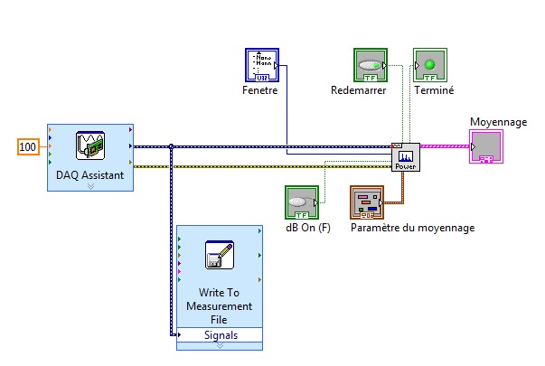
I need the raw ADC output card PCI-4462 using DAQmx
I need the raw ADC output card PCI-4462 using DAQmx
Is it possible or are only regulated units availible.
Ken Manatt
There is a version of 'Raw' DAQmx Read (see image). This is probably what you are looking for.
-Alan

-
Can I interface SR510 through card PCI/IEEE488.2 32-bit using the Labview software?
We have a card PCI/IEEE488.2 of IOtech instrumentation. Now, I want to lock interface amplify (SR510) through this card with the software LabView 7.1, is this possible?
My GPIB, IEEE488(frm IOtech) card are working properly tested by IOtech IEEE488 Labview test file. I have no error result. Now, for my practice, since the beginning I want to interface KEITHLEY 236 source measure unit. I downloaded all the drivers keithley236 Labview in the instr.lib folder. When I run that these files, it does not answer. I can't understant what is the problem. Please tell me.
-
I recently blocked my macbook pro using find my iphone app now, he continues to display in 'your computer is disabled. Try again in 60 minutes. I tried pressing the option key and also the R button at startup. same thing is happening.
Hi iambjan,
I understand that your MacBook Pro has been lost by the intermediary of find my Mac mode. Fortunately, you can go to the off mode lost through the steps described below.
You can disable the lost Mode by entering the password of the device, or by following the steps below. Alternatively, you can follow the steps below to change the details displayed on your lost device.
Note: If your credit cards and debit to pay Apple have been suspended because you put your iPhone in lost Mode, when you disable lost Mode and reconnect to iCloud, you can continue using your cards.
Go to find my iPhone on iCloud.com.
If you don't find my iPhone on iCloud.com, your account has fair access to the web features only iCloud. To access find my iPhone and other iCloud features, set up on your device iOS or Mac iCloud.
Click on all devices, and then select the device that is lost.
Click on lost Mode, then change the information or lost the stop Mode.
If you cannot use lost fashion as find my iPhone is not configured on your lost device, see the article by Apple Support If your iPhone, iPad or iPod touch is lost or stolen.
SEE ALSO
Remove credit and debit of the portfolio (or book) mapsiCloud: use lost Mode
https://support.Apple.com/kb/ph2700Kind regards.
-
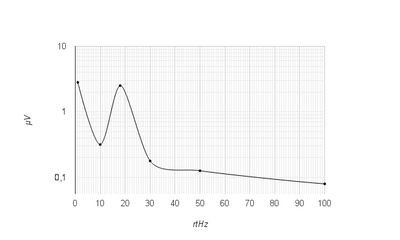
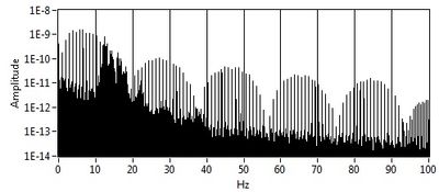
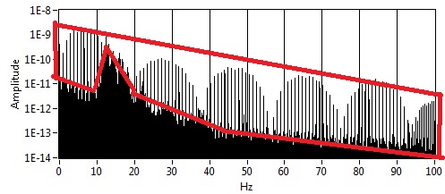
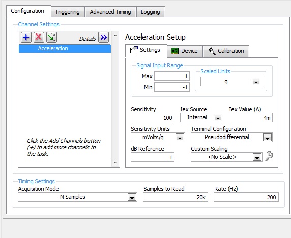
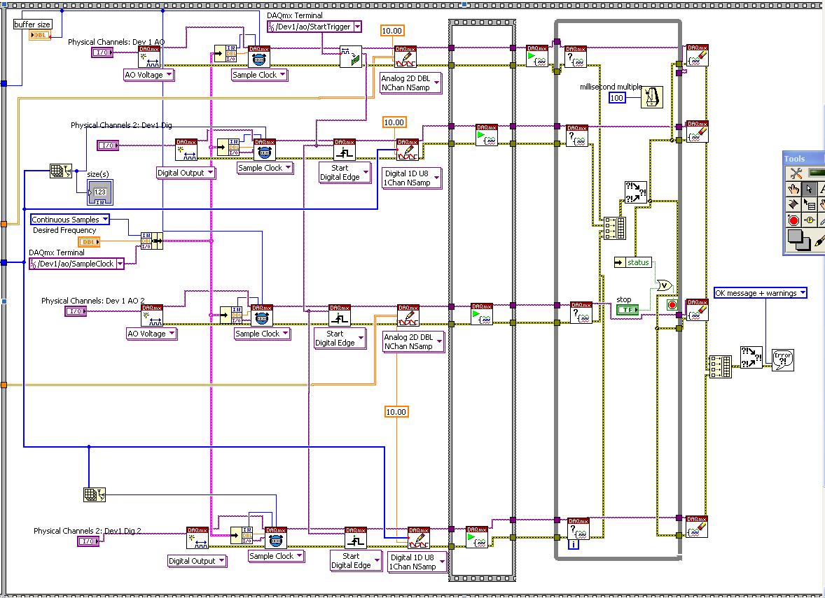
Noise measurement of an accelerometer with card PCI-4461
Hello world
I'm trying to measure the noise of an accelerometer, except with a card PCI-4461.
First of all, I measured manually this noise with the help of a HP35665 signal Analyzer. I get something like this:
And now with LabView and the PCI-4461 map, I get this:
My question is: Whence this part? And how to remove it? (Since there is no with the signal Analyzer)
I'm using LabView 8.5.
This is how I configured the DAQ acquisition:
and it's my VI:
Thank you in advance for help
Arthur
-
Several cards PCI-MIO-16-4 in a PC
Hello
I have two systems on the same SCXI, using a card PCI-MIO-16-4 to control instruments in a chassis. Currently, I am working on the new software to combine these two systems in one, but without any hardware revisions. Because of the distance between the two chassis, I don't have the ability to chain the. Is it possible to use both PCI-MIO-16-4 cards in a PC at the same time? Thank you very much for your help!
-Eric
Hi Eric,.
Assuming that you have available PCI slots in your computer, you can use two cards PCI-MIO-16-4 in a computer simulatneously.
-Jake B.
-
Hi, I would ask for some help to get a better understanding of the works of the FPGA. I use PCI-7833R. As the field programmable gate array, each time I want to launch a new FPGA vi, without using the emulation, the program is compiled in the table. This means that some part of the Bay door is irreversibly programmed? For PCI-7833R, how many times can I compile my FPGA vi on the motherboard? How much space does have? It would happen the whole picture card is programmed and I can't use the card again? Thank you very much! I appreciate any help or information. Any reference or basic documents would be much appreciated as well.
soljiang:
The FPGA is fully reconfigurable, so if you place a new VI FPGA on your 7833R, crash just any previous configuration and it won't run out of space. The FPGA programming is NOT irreversible, so don't feel bad if you need to change your VI and recompile; prototyping, as this is precisely what the Board is designed for.
The 7833R a Virtex-II FPGA, then wear it hs 3 million (see tables in the following items or the page of the product here).
If you are looking for basic documents, here are a few good ones on the NI Developer Zone.
-
Why do I get error "20019 ADC conversion failed" with my pci-6143, when I try to use the DIO lines?
I am tyring to use one of the digital input lines on my PIC-6143 to go to the connection "enable" on the "write to file measure" vi. I have two cards PCI-6143 acquiring analog signals of 8 channels per step, plus I have a digital DAQ assistant to the sample line of DIO 2 on one of the cards. Normally I can start and stop recording using a signal of 5V to the DIO port several times until I get the error.
Strangely, when I use a simple Boolean "Record" button at the port of the 'writing on a file as' enable vi, I never get this ADC error no matter how many times I press the button.
I am including a screenshot of the error.
Thank you
Chris
Please ignore this message. The whole issue has been resolved by copying and pasting the VI in a new file in VI. The new file ran perfectly. Must have been a compilation of LabView or something error.
-
OR PCI-6542: Creation of dynamic waveforms using the HSDIO library
Hello!
I have problems to understand how to create waveforms using the HSDIO library to run on a card PCI-6542. I need to create a program that activates a channel for 12.5 microseconds, waiting for a while (i.e. 100 samples) and activates another channel to 12.5 microseconds.
This program must be used in a Multielement ultrasound system.
Here the example of dynamic generation program that transforms the channels 0-2 on 1024 samples.
/************************************************************************
*
* Example program:
* DynamicGeneration.c
*
* Description:
* Generates a simple model on the specified channel.
*
* Pin connection information:
* None.
*
************************************************************************// * Includes * /.
#include "niHSDIO.h"./ * Sets * /.
#define WAVEFORM_SIZE 1024int main (void)
{
ViRsrc deviceID = 'Dev1 ';
ViConstString channelList = "0-2";
ViReal64 sampleClockRate = 50.0e6;
DataWidth ViInt32 = 4;ViUInt32 waveformDataU32 [WAVEFORM_SIZE];
ViConstString waveformName = "myWfm";
ViInt32 timeout = 10000; / * milliseconds * /.ViSession vi = VI_NULL;
Error ViStatus = VI_SUCCESS;
Bruno errDesc [1024];
ViInt32 i;/ * Initialize generation session * /.
checkErr (niHSDIO_InitGenerationSession)
Deviceid, VI_FALSE, VI_FALSE, VI_NULL, &vi));/ * Assign channels for dynamic generation * /.
checkErr (niHSDIO_AssignDynamicChannels (vi, channelList));/ * Set up the clock sample parameters * /.
checkErr (niHSDIO_ConfigureSampleClock)
VI, NIHSDIO_VAL_ON_BOARD_CLOCK_STR, sampleClockRate));/ * Query the data Width attribute * /.
checkErr (niHSDIO_GetAttributeViInt32)
VI, VI_NULL, NIHSDIO_ATTR_DATA_WIDTH, & dataWidth));
/ * Fill the waveform with ramp data * /.
< waveform_size;="">
{
waveformDataU32 [i] = i;
}checkErr (niHSDIO_WriteNamedWaveformU32)
VI, waveformName, WAVEFORM_SIZE, waveformDataU32));/ * Start the generation * /.
checkErr (niHSDIO_Initiate (vi));/ * Wait for all the generation * /.
checkErr (niHSDIO_WaitUntilDone (vi, timeout));Error:
If (error is VI_SUCCESS)
{
/ * Print result * /.
printf ("made without error. \n") ;
}
on the other
{
/ * Get the description of the error and print * /.
niHSDIO_GetError (vi, & error, sizeof (errDesc) /sizeof (petitioner), errDesc);printf ("\nError encountered\n===\n%s\n", errDesc);
}/ * log * /.
niHSDIO_close (vi);/ * prompt to go out (for the popup console windows) * /.
to continue...\n");
GetChar ();error return;
}Issues related to the:
How can I change the values in waveformDataU32 to create market reports (instead of just always on)?
How to select the channel waveformDataU32 is applied to the?
Thank you!
Zachary Geier
The waveformDataU32 table is an array of 32-bit integers. Each bit corresponds to a line on the device. On the first clock cycle, this program outputs:
0000 0000 0000 0000 0000 0000 0000 0000
Then it displays the following, changing at each clock Pulse:
0000 0000 0000 0000 0000 0000 0000 0001,
0000 0000 0000 0000 0000 0000 0000 0010,
...
and so on all the way up to 1023:
0000 0000 0000 0000 00000011 1111 1111
In the example that you include at the bottom, you set the least significant bit (LSB) to zero and one, actually only change one line on the output. To change all the lines, you must instead use 4 294 967 295 or 0xFFFFFFFF:
< waveform_size;="">

     < 200){="" if="" sample="" number="" is="" less="" than="">

          waveformDataU32 [i] = 0;     Disable channels 0-2

     }

     else {}

          waveformDataU32 [i] = 4 294 967 295;     Otherwise turn on all channels to 800 samples

     }

} -
card PCI-7332 performance is slow
To using a card PCI-7332 in a Win7 pc and it runs slow. By slow I mean what is specified in the 7330 OR and the Timing of 7340 NOR information sheet States that my while loop should run at a speed of 10 ms. His race in a rate of 125ms.
Please see the screenshot of the vi below.
I don't think there would be a significant improvement by moving to a RT system. It is true that there is less processing overhead compared to a pc, but the algorithms are the same. A RT system would be more helpful if you were more interested in a more deterministic control. You must use a RT system if you wanted the iterations to be ' one time ' not necessarily faster.
-
To increase the flow of a Basler Cameralink Camera (A504K) with a capture card PCIE-1429 card
Hello
I use a monochrome camera of Cameralink Basler A504K-resolution 1280 x 1024 with a capture card PCIE-1429 (x 4 slots) card. The image acquisition is controlled by MAX of LabVIEW version 11.0.1. The problem is that when I try to reduce the number of lines (specifically height) 1024-32 (for example) in the window of acquisition (from MAX), the frame rate of the camera is expected to increase to almost 16, 000fps. But it does not go beyond 248fps. Can you suggest me, why is he so past, or how to increase his pace? In addition, under the image window has appeared has something like: 1 X 8-bit 1280 x 32 9 image. That 1 X means here? For your reference, I am also attaching the image of the purchase window.
Thank you!
Hi Római,
Change the height of your image in MAX will not increase the rate of your acquisition - the camera always sends the same number of lines per image, you said just the software to stop their playing earlier. The following image still occurs until the next edge FVAL.
1 x at the bottom tells you view the image at 1 x magnification. In MAX, you can zoom in and out, and this indicator lets you know your current zoom level.
-
Error 200452 with synchronization of two cards PCI-6733
LabVIEW: 8.6
Using two cards PCI-6733 connected via a RTSI cable, I'm trying to get an output synchronized two PCI cards (which are connected to of BNC-2110).
Here is the labview code I put together by looking at the examples online and in the program. To the left of the diagram is the part of the program that generates the entries.
Currently, it gives me an error 200452: "specific property is not supported by the device or is not applicable to the task." Property: task of Start.TrigType name: _unnamedTask<26>. »
Any ideas how to solve this problem? The Labview code above looks like it will do what I want?
Thank you
After investigating further the code, since it seems that your referencing the same clock, you do not need a trigger. You can probably avoid the error by removing the third blpck on all threads
-
Center media card PCI TV Tuning problems
Since the digital switchover I can no longer use Windows XP Media Center to watch TV. My TV PCI card is a device Hauppauge Nova - T 909 dual channel TNT but who has already worked with library and is currently working with the Hauppauge software, used to the library to find all channels when scanning for them. Also, I get an error message saying the tuner cannot be found or the antenna is not connected, which is clearly.
I deleted, canceled and rebooted Hauppauge drivers etc and no indication in device, malfunction management. Windows is also updated
Any help would be appreciated
The digital switchover has caused far more problems than most of the people living in big cities and realize populated areas. The switch was made for these main reasons:
To free up airways for the fast growing demand for cell phones.
Digital is also much less space than analog.
Digital reception is more clear.
The Government owns the Airways and can now sell free space and make billions.
I'm also affected my cell internet connection (which I am on now) decreased by greately and my cell phone. It's because I live on a mountain in an uninhabited area and my cellular company is not interested to spend millions to build a tower in my neighborhood and the digital switchover affected my reception. High demand reduced reception quality.
However, it is temporarily more side, I have a TV Tuner analog and I still get the signal. Reason in low population areas were not required to pass even if some switched in any case this is why "temporary".
All major cities have been required to spend as well as highly populated areas.
All that being said:
I'll assume that your device is both digital + analog and you installed a driver for the two. Try to uninstall the driver only analog or only digital driver (depending on where you live).
You can also try uninstalling the software Media Center capable of most of the options.
You said antenna: if she is drinking, it is most likely your problem. If you were in analog and digital now a portable antenna or an antenna outside normal is able to receive the siginal for a distance of about 10 miles only. Try first at this stage. Get a better antenna but attention, more regular external antennas announced for you give incredible reception are a fraud. Before buy you a try on a different surface even though it's a pain to lug your PC it unless you have a laptop.
One last note on digital and analog when you use an antenna.
If the reception is poor with analog you get snow or lines, but you still have a picture no matter how it is!
If the reception is poor with digital, you have no image at all your TV becomes black or you receive a message from your computer saying the tuner cannot be found or the antenna is not connected.
(Some people also have a temporary loss of signal due to maintenance on the towers)
-
port mini-PCIe for WAN on other X120e uses
Hi, I ordered as a X120e without the conectivity WAN option so he came without the card, but I have this mini-PCIe available, is it possible to use this port for something else? I wanted to put a second wifi card for the tests of penetration and research... or even a solid storage card in there.
Well, unless hack you the BIOS to the white list what wireless card you install, it will be a moot point. In addition, you must find an ssd pcie with an integrated controller which presents itself as a drive controller, of which none of those available, I know of no. So, in conclusion, unless an engineer comes out and says he can endure more, chances are that we cannot use it for anything apart from Lenovo wireless cards.
Maybe you are looking for
-
The tabs are on the top, how to place under the bookmarks bar?
Just set Mozilla to update to the beta 29,0. My browser has been configured as follows: File, editing, display etc. are first;then there's "home" button and the address bar.then bookmarks bar;and finally the tabs. Now the tabs are at the top of the a
-
Hello I would like to know how do we wrap text in a column in a table 2D channels. If I try to wrap an array in its entirety coloumn gets hit. Please see the image to get a better idea. See how the numbers, compared to the texts. How can I wrap the t
-
event ID 1000 and event ID 1001 related to casetup32.exe and ImmunetProtectDriver
Hello world I have a question. I run this PC on Windows XP SP3. a few minutes earlier, when installing Immunet 3.0, they kept appearing, several error messages associated with casetup.exe. I checked under Component Services and. Failing application c
-
Possibility to send e-mail to later a date and a time
I am wanting to create emails today and sent as reminders before each football game and practice throughout the summer. How can I set up the email to send automatically to future dates...?
-
My computer won't allow me to open any pdf file.
When I try, get a window telling me that I have not all devices (scanners, cameras, printers) selected. What is going on?