cDAQ-9184 AI DO
Community of hell,
I'm working on a chassis OR cDAQ-9184-one module (NI 9474) and two modules of it HAVE (NI 9215).
The task is to acquire analog measurement and generate a pulse train to trigger a Laser sensor. Please find attached my simple diagram.
The challenge here is to know how to sync the and GOT them. As a newbie in this area, I get several questions as follows:
1. for synchronization multifunction, I need route my output internal counter to the task of AI as a sample clock. In NI MAX I can find this source in the advanced calendar section. However, in Labview, this CtrxInternalOutput is not available in the DAQmx Timing.vi. Do you have an idea what could be the problem?
2. during the measurement, I got 6590 HAVE measures and 6699 laser that are triggered by the pulse train with a sampling frequency of 500 Hz. It seems that we do not get the same amount of HAVE and. What could be the problem?
3. information on this synchronization, in my opinion, we must configure the same sampling rate, the same same sample clock and HAVE & acquisition start together. Am I wrong? The difference in the number of samples is possible due to IT & do not stop at the same time, when I press stop in Labview?
Thanks for your help.
-sparkle
1. the "Advanced" are hidden by default.
2. There are two issues:
i. you must start the task I face the task of meter output while he is in time for the first edge of clock.
II. to make sure that read you the same number of samples in the form of impulses generated, you must stop the task of output of the meter and make sure you read back all the samples that were in the FIFO of AI.
3 see #2.
Best regards
Tags: NI Hardware
Similar Questions
-
Cannot get DAQ Assistant in Labview to cDAQ 9184
I am trying to build a system for the acquisition of data with one NOR cDAQ 9184. I installed the drivers for the system and I'm able to get to the DAQ system using NI Max (under my system - devices and Interfaces - devices on network) and all channels appear well, however, I tried to follow the procedure described in http://www.ni.com/white-paper/11703/en/#toc2 to integrate my system with LabView and I am unable to find the tab software under the unit to be able to write the RIO 3.5.1 on the appliance and cannot find the device to through the LabView project.
Your real problem is error-50103. This is a common mistake, and you can find the answers for it if you are looking for in the forums.
The problem is that you can't have several tasks (or several assistants DAQ) try to access the same device at the same time.
Make a DAQ assistant who has all defined channels you wish to purchase.
-
Hello
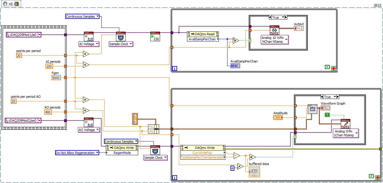
I 9184 cDAQ chassis with two modules installed: NEITHER 9215 (HAVE) and NI 9263 (AO).
AO generates the signal of 5 kHz and bought it. Initially, all right, but after 20-30 seconds, it has delays (up to 30 seconds!) between the production and acquisition.
Time lag depends on the speed of the DAC. If it 20 * 5000 = 100 kHz, delay = 15 sec, if it 10 * 5000 = 50 kHz, the delay is 30 sec.
It works with the PCI - DAQ version, but I do not understand why he has these delays with ethernet chassis.
I tested it on gigabit ethernet with chassis directly connected to the host. But I don't think that problem is on a network, because the net charge is 0.55% and ~ 1Mb\s data transfer. The processor is also low.
And I think evil isn't in the generation, acquisition, as it evacuates all samples in buffer (number per channel in DAQmx read nearby 'availsamplesperchan') and because changing CAD rate influence on signal updates.
In addition, it works fine without these big delays to signal lower rates, for example, sine wave 50 Hz generating.
Example of code is to join. I read 100 times of 5 kHz sinusoid, 16 points per period (refresh rate = 80kHz, 1600samples). And 5 kHz sine generation of 100 periods with 20 points per period (rate is 100 kHz, 2000samples).
Now, this works in two separate loops with the control "TotalSampPerChanGenerated".
Problem was with a buffer too small mailing to cDAQ. 8 k samples and 4 caching works pretty stable buffers.
Also, I checked the difference between 'CurrWritePos' & 'TotalSampPerChanGenerated' and the maximum value is 1 500 000. 1 sample is it DBL, it really means that the buffer size is 1.5 M * 8 bytes = 12 MB.
Thanks for the thread.
-
cDAQ 9184 with module NI9232 for sensor accelerometer and pressure
I'm currently building a CompactDAQ system for measuring two signals: vibration and pressure in the duct system. The system will consist of the following elements: chassis, NI 9232 Module cDAQ9184. Accelerometer IEPE to measure acceleration (vibration) and pressure for the measurement of the pressure sensor. My question is: can I connect the pressure sensor in the NI 9232 module? I have found on the site OR that this module is designed for acceleration and offers a conditioning of signals and excitation for accelerometers but nothing mentioned about pressure sensors. On the other hand the site mentions NI9237 module as the best choice for pressure sensors. So can I just use 9232 OR both sensors or not. Thank you
Here's an IEPE (source of ICP (r)) of transducors pressure: http://www.pcb.com/products/browse_productlist.asp
Kistler is another provider.
To help choose - can you tell us more about what you are going to connect the sensors - what is the unit under test?
What do you do in the hope of discovering or surveillance of the unit?
-
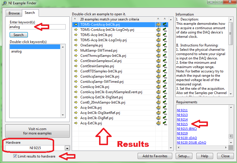
Looking for examples of 9184/9263/9215
Well, obviously, I flood the forum tonight.
I've never used NiDAQmx before, so I'm looking for examples of code in CVI for a cDAQ-9184 with AO 9263 module and an AI 9215 module. I imagine that there are examples of code for hardware compatible with different names, but after a quick search using [help] [NOR example Finder] I could not achieve what either.
Thank you
9184 chassis has no specific software.
If you add the 9215 to loss of material select and check "Limit resusts to material", next search for 'analog', you will find a series of examples which can be executed on the module. It goes same for AO module you have.
-
Hi all
I got the update from an old soft of NOR-DAQ to NIDAQmx trad (thanks guys!) but I have a question about the distribution.
If I create a Setup program with only NOR-DAQmx run, it's already 300 MB but when I install it on a blank PC, hardware (chassis cDAQ-9184 ethernet) is not detected. NOR-MAX is not installed with this option.
If I install the driver NOR-DAQmx run with the help of configuration, of course NEITHER-MAX is installed and I can configure the material here and everything works, but it is 1 GB.
Is it possible to get the chassis Setup and its taken housing device supported directly from my sweet on the 1st round? In addition to this any other solution?
Thank you
If you use MAX configurations, you must use the version of the runtime DAQmx with the help of the configuration. It is possible to configure your tasks programmatically and channels without the use of MAX. You must use DAQmx property nodes in your code to return a list of available devices, choose a program you want to use. You must implement your tasks programmatically by using the correct DAQmx resource.
-
cDAQ against RIO Ethernet expansion chassis
Could someone tell me if the NI 9146 Ethernet RIO expansion chassis can be used with Labview on a Windows PC without real-time or FPGA module? He would consider a network device in MAX? The cDAQ-9184 would probably my needs, but I would like the capacity of maximum temperature higher the 9146.
Hello rdtech,
You can use the expansion chassis NI 9146 Ethernet RIO with only LabVIEW on a host PC, and you don't need LabVIEW Real-time and FPGA module, however, you must the NI-RIO driver. In addition, the RIO Ethernet would be seen as a network device, that you expect.
You will use the mode Scan Interface expansion chassis, which is a special configuration of FPGA, which is supplied with the driver that allows to browse through all the channels available on the chassis. This does not require the FPGA module because it is already compiled and included with the driver.
One thing I want to emphasize is that the coding will be different than using a cDAQ and DAQmx drivers, you rather read individual channels directly instead of creating as DAQmx tasks. If you would like to, you can create a new project and start the host PC code for this system by adding in the 9146 and modules for the project without having them physically on the network
If you are uncomfortable with the not using the DAQmx driver, I think that the 9146 OR would work well for distributed data acquisition and enjoy higher operating temperature.
See you soon,.
Joel
-
To input analog shutdown when the analog output is completed and synchronization
Hello
I'm trying to get my LabVIEW program to send analog output to a computer and read acceleration using the cDAQ-9184. Chassis output that I use is the NI 9263 and the chassis of entry is the NI 9234. I generate a signal of white noise using LabVIEW Express signal generator.
The first problem I have is the synchronization. I had an old VI that has begun to measure the acceleration just about a second after the entry has been given to the machine. I used the LabVIEW tutorial on how to sync the analog input and output, only to discover that it does not work with two different hunts. Then I found another tutorial that shows how to synchronize different frames between them.
The second problem is the cessation of the LabVIEW program. What I want to do is to generate the signal and then simultaneously send and read the input and output analog, respectively. It is because I don't want a phase difference or any shorter signal for a direct comparison. But as soon as the signal is sent to the machine, I want the entry to stop analog playback and then then the LabVIEW program must stop. I want to be able to choose any length of signal to be generated and stop as soon as the entire duration of the signal has been sent to the machine.
I tried 'DAQmx stop', "DAQmx Timer" and 'DAQmx's task made?' and none of them have worked for me. It is also my first time on a forum posting, so I hope I gave enough information. I enclose my VI as well. The VI shows I read an entry for the analog input voltage, but I am only using this to try to get to the work programme.
I'd appreciate any help I could get.
Thanks in advance
Peter
Hi Peter,.
I have some recommendations for you that I think you will get closer to your solution. First of all, I assumed you meant that you had 1 chassis (cDAQ-9184) who had two modules in it (NOR-9263 and NOR-9234). My next steps are based on this assumption, so if it's wrong, please let me know.
For your first question about the synchronization, the code you provided is very close to what you need. You need to do, however, implement architecture master/slave for startup tasks DAQmx functions. To do this, you can add another frame to the flat sequence structure and put the master start task (input voltage) after the start slave (output voltage) task.
To manage your second question and that the program ends at the point where you, the first step is to get rid of all the logic that you use with the local variable of length of time. Rather than use this logic, just wire the node "task performed?" of "is task performed?" operate to stop the loop. This will cause your loop to stop as soon as the signal is sent to the machine.
I have some other recommendations for you that will increase the performance of your program:
(1) rather than writing on file inside the last loop, you can use the DAQmx Configure Logging (PDM) .vi. You will place this VI between DAQmx Timing.vi and DAQmx Start Task.vi to the task of the analog input voltage.
(2) after the last while loop, you want to stop the task and analog outputs as well with another DAQmx stop Task.vi.
(3) rather than using a local variable for the entrance of displacement and wiring it in the DAQmx Write.vi, you can wire directly from the output waveform of the wave to build function node.
That should help you get started in the synchronization of these tasks.
-Alex C.
Technical sales engineer
National Instruments
-
Why the my linear encoder is only tend to read negative?
I have a linear encoder, that I am using with one NOR cDAQ 9184 & 9401. I basically used the example of linear encoder, I found here on the website of OR, however, when I run the program I find that measuring only in one direction is the precise movement of reading. By this I mean when my encoder moves upward (actually my camera moves down and the encoder is fixed) I can move properly, but when moving in the opposite direction I'm away. I'm not a linear sum, very different each time. Sometimes when the movement he began first almost looks resets the unit to its original position (0 "), but I am helpless as to why. Does anyone have an idea on how to remedy this situation?
I'm pretty confident I have things wired properly while this same configuration/encoder reads correctly in MAX, see the second screenshot.
Well it seems that the question was much easier than I thought. Of course, I'm a newbie to this, but I think that most of the confusion was due to the lack of detailed information. None of the documents of OR really explained me the option counts two impulses, more the X 4 and documentation of the mentioned readhead times count four. However, after receiving no not any solid solution, I started completely over and tried all the options I had along the way. In short, my solution was to simply what I posted in my screenshot, but simply change the X 4 option for counting of pulses two option.
-
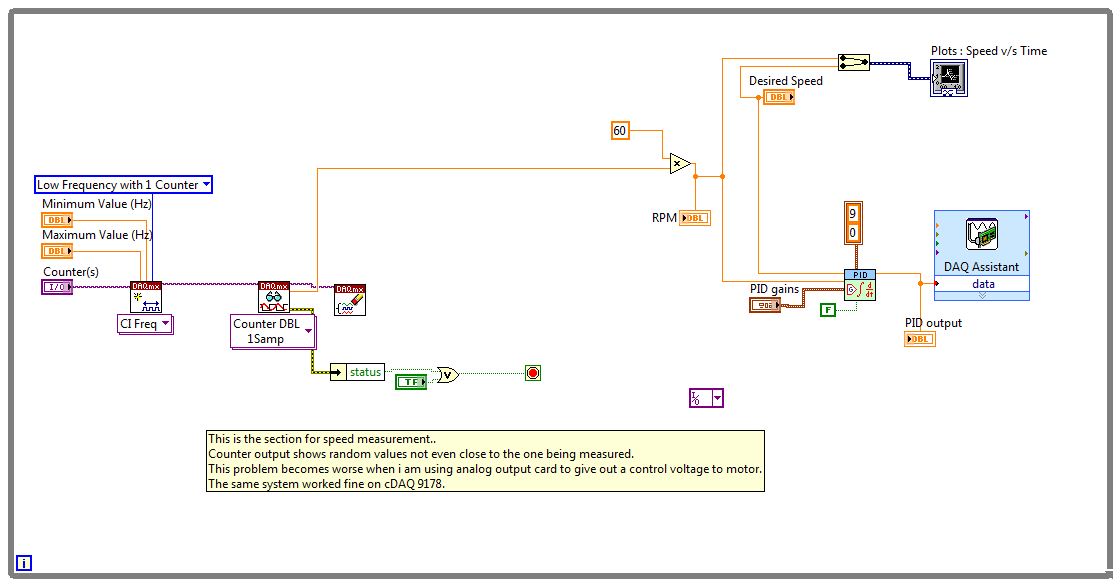
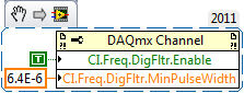
I use cDAQ 9184 and 9401 digital I/o card, I use the counters available for the measurement of the frequency (pulses are generated by a sensor hall, whose frequency I want to measure to estimate the speed of the motor DC.) But the problem is that this counter returns garbage values. I tested the card and its counters that they are working correctly. What could be the possible causes of what is happening?
attach a snapshot of the VI.
Please hep out me as soon as possible.
Thank you and best regards.
Are these garbage values much higher frequency than you expect? If so, you're probably picking up noise and should allow the filter PFI for your task.
Best regards
-
NOR-DAQmX hardware synchronization for module 2 OR-9223.
Dear all
I use NEITHER cDAQ 9184-2 NOR-9223(1M) analog acquisition module 6 input channels of the sensors of acoustic emission (frequency of 20 to 400) with external signal conditioning.
Please please let me know how to synchronize using NOR-DAQmX? NOR-9223 does support hardware synchronization?
Thanks and greetings
Luong.Tran
Hi QuanLuong.Tran,
here http://www.ni.com/white-paper/4322/en/ you can find how to trigger and synchronize the different channels. It should work.
Best regards
CaravagGIO
-
Hello:
I have a cDaq 9184 and a module or 9401: I'm trying to measure two frequency inputs to the nor 9401, with values between 100 to 2 Mhz and software configuration for each is 'wide range counter' and 'frequency' selected for them on counter vi entries. The outputs of these two devices are to open with max 5 volts collector and pull it upward resistance which can vary between 100 and 1000 ohms, signals are connected to pins 14 (PF0) and 19 (PF3) and two Commons are both connect.
Devices are RADIAN wattheuremetres and I can see the balance budget real values and Radians and Radians are compared to a national standard and they have errors between +/-0.02%, but when I check the values displayed in LabView errors are bouncing around +/-10%, and there seems to be some noise. I tried all optical coupling, c-mos, with doors schmitt triggers AND and nothing seems to work. So I checked the resistance between pins 14 and 19 and I'm appoximately measured 38 kohm and then measured the two pins in common with 8.8 kOhm resistance: If the pins 14 and 19 should not be infinite?
Thank you
Alan
Hi alannspower,
You're right - the resistance must be very large (infinite). How will you measure these exactly? Also, have you tried to measure the other pins to see if they have infinite resistance, we would expect?
-
Greetings,
I'm working on a pump shrimp. I have problems of measurement of voltage across a shunt when tension, it reaches a certain point (~ 13 Volts or more).
Reading, as seen in the excel worksheet, takes a dive until the voltage on another channel is measured under 13V (it is in fact through a voltage divider 1/5).
Material:
NEITHER cDAQ-9184
NEITHER 9211
NEITHER 9402
NEITHER 9207
R shunt = 0.0005 ohms
I have attached the excel file of data where the measure of incorrect amperage appears in red. He did this on another pump as well.
When the input voltage is greater than 13.0 Volts (on the 1st channel of the NI 9211), the shunt voltage difference (on the 2nd channel of the NI 9211) would jump down in value.
It ruins my collection data will more 13.0 volts.
I'm looking for advice on how to solve the problem. I'm not sure if this is a hardware problem or a software that needs to be changed.
The volts are read by a voltage divider, but they have been accurate to date.
Thanks in advance,
-Tom
It is the voltage to the DAQ entry that counts with this.
For differential inputs, it is not the differential voltage that matters. Each entry in the differential input must be less than 10.2V to the town (on the ground).
-
Sample clock dependence with small signals data acquisition
Hi all
I use a NOR-9205 on a NOR-cDAQ-9184 and noticing some interesting dependencies of waveform on my sampling rate selected. It seems that small changes in the sample clock frequency have a significant impact on the measured waveform.
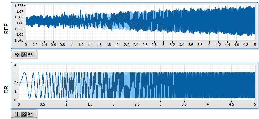
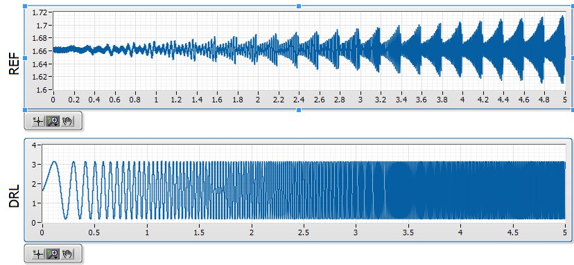
Quick background, I am in a position a signal with a ripple of mV ~ 10 with V 1.6 bias. I'm not interested in DC, only the AC signal but the NOR-9205 has only DC coupling. The application is a circuit where I expect simulations noise past the circuit must be greater than the higher noise frequencies. In the waveforms attached the background plot is the applied signal, and the top graph is the signal arising after that the signal was mostly annihilated. The two waveforms are measured with the NOR-9205.
I am aware that this measure is less than the precision of the NOR-9205, which has a maximum precision of ~ 3 mV in his +/-5V range. However, if I can't at least on the basis of shape which is good enough for me. I'm also now pretty curious that data acquisition is actually to create this
My best idea, is that it is a product of internal multiplexing of the 9205 with the DAC.
The first plot shows the waveform at 20 000 Hz, which is what I expected:
The second shows the waveform at 20 001 Hz, which seems to be modulated with a backup sawtooth:
The waveform looks as expected for 20 000, 20003, 20004, 20005, 20008, 20009, 20010 and Hz 20011. The waveform looks like modulated to 20001, 20002, 20006 and Hz 20007.
Ideally, I would like to understand this problem so that I can configure the measure in a stable way that I can count on the basic shape of the wave. Has anyone seen something similar?
-
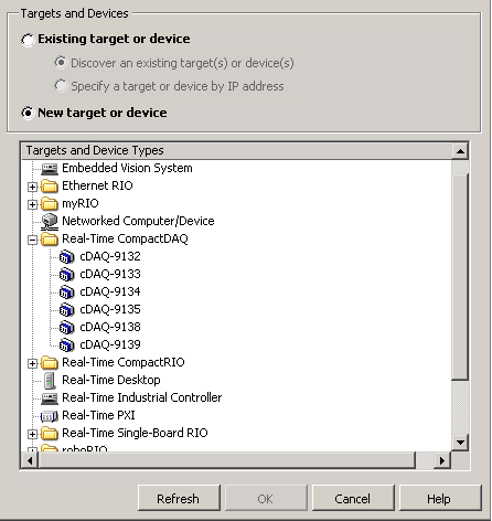
LabVIEW 2014 does support CDAQ 9136
I use LV 2014 SP1, I wanted to buy CDAQ 9136 Windows controller for one of my projects. I'd like to figure out if I can use the SP1 of 2014 LV with DAQmx15.1 in the program for this controller? User manual CDAQ 9136 does not say anything on the support of LV, just said that DAQmx 15.1 is supported.
When I tried to add a target CDAQ in SP1 LV2014 with DAQmx15.1, it does not show the CDAQ 9136. I won't use the real time of the CDAQ 9136 version, but I'm confused. Any help would be greatly appreciated.
Nanda,
I would like to clarify the compatibility for the NOR-9136. It is compatible with DAQmx, starting with DAQmx 15.1. In other words, it can be used as a normal cDAQ chassis in any version of LabVIEW with DAQmx 15.1 or later installed (within reasonable limits). However, compatibility in real-time with the cDAQ-9136 has not introduced before LabVIEW time real 2015 module, which is only compatible with LabVIEW 2015. Thus, to use the cDAQ-9136 as a real-time controller, you will need 2015-LabVIEW and the module time real LabVIEW 2015 or later. This note can be found in DAQmx 15.1 notes for supported devices.
Maybe you are looking for
-
Thunderbird on Windows 8.1 sends a message without error, but the mail is not delivered.
New laptop Toshiba current A6 running Windows 8.1. Installed Thunderbird 31.6.0. Configuration completed successfully. Am able to receive the mail, but cannot send. When I send mail, I see the message "connecting to Server" and "mail sent successfull
-
Firefox updated 19 and freezes
Firefox automatically updated itself in version 19, now I can open the browser, but whenever I open a new page, or click on what that either the upper part of the browser will gray and I cannot do anything, all my icons, tabs etc are grey and cannot
-
Tecra R840-109 - alert HDD - unable to get disk information
I turned on my Toshiba Tecra R840-109 and everything looks that the factory settings have been restored, but I still have my files on the hard disk in the users folder (where the system has also built a temporary user I'm connected now, I guess). At
-
Error: "your account has been blocked; You can't go to your account because your parents he blocked.
What can I do if I see this error in Windows Live family safety?
-
any solution easy errror 1635 vista will not download adobe