9401
Hello:
I have a cDaq 9184 and a module or 9401: I'm trying to measure two frequency inputs to the nor 9401, with values between 100 to 2 Mhz and software configuration for each is 'wide range counter' and 'frequency' selected for them on counter vi entries. The outputs of these two devices are to open with max 5 volts collector and pull it upward resistance which can vary between 100 and 1000 ohms, signals are connected to pins 14 (PF0) and 19 (PF3) and two Commons are both connect.
Devices are RADIAN wattheuremetres and I can see the balance budget real values and Radians and Radians are compared to a national standard and they have errors between +/-0.02%, but when I check the values displayed in LabView errors are bouncing around +/-10%, and there seems to be some noise. I tried all optical coupling, c-mos, with doors schmitt triggers AND and nothing seems to work. So I checked the resistance between pins 14 and 19 and I'm appoximately measured 38 kohm and then measured the two pins in common with 8.8 kOhm resistance: If the pins 14 and 19 should not be infinite?
Thank you
Alan
Hi alannspower,
You're right - the resistance must be very large (infinite). How will you measure these exactly? Also, have you tried to measure the other pins to see if they have infinite resistance, we would expect?
Tags: NI Hardware
Similar Questions
-
I can measure the speed of the NI 9401 fan & cRIO 9075 under Scan Interface?
Hello
I am currently using OR 9401 & cRIO 9075 to develop a project, which is to control the CPU fans.
Since I have to communicate with other instruments by serial port, while I have a NI 9870 module to implement the instrument control.
I finished the part of control instrument under scan mode and would like to add the function of the fan speed reading.
Now, I wonder if there is a problem when I choose the Scan Interface to deverlop the program.
I found the following tutorial, he uses the FPGA interface to impement the acquisition of control and PWM frequency.
http://www.NI.com/white-paper/3230/en/
So if the function of the fan control only developed under an FPGA interface, I have to rewrite the control instrument part, seems to be a bit complicated...
You can use the hybrid mode.
http://digital.NI.com/public.nsf/allkb/0DB7FEF37C26AF85862575C400531690
-
Is a module able to drive a small 9401 (5amp) SSR with a 4-15 volt of entry?
You should consider using a buffer chip that can produce current, you need, like this. This will require a 5V supply, but it does the job.
-
I have a 9401 on a chassis 9188 module. What I want to do, is to have 3 DI, 1 and 1 PWM.
I thought I could put the DI 3 on channels 0,1,2. Output channel on 6 and a PWM using a digital channel 7 (-1). In this way, that they would be grouped with 1 4 input channels and the last 4 production by the manual.
The problem is I get a 201133 error that says that the device can be configured for input or output due to another task or directions when I try to run everything in the same vi. I can make the DI and DO tasks with no problem OR the PWM task without problem. I tried to book the tasks with the DAQmx control task VI as the suggested error, but not luck.
Is it possible to do all this on the 9401 at the same time?
Bryan
You won't be able to use 1 DI, 1, and up to 4 meter which are material tasks timed at the same time when you use a 9188: http://digital.ni.com/public.nsf/allkb/5E0B829E50ADE1BC86257AC50062B2D2?OpenDocument
In addition, you will need to make sure that you book the tasks to avoid the error of 201133 with the 9401: http://digital.ni.com/public.nsf/allkb/0495B7D5E2345DF386257730007EFD17
-Mike
-
cDAQ-9178 & NI 9401 - ASM: incremental Rotary encoder works is not beyond a certain frequency
I use a chassis with a NI 9401 DIO module 9178 cDAQ. I'm trying to convert the output of a rotary incremental encoder ASM (in radians) to rpm.
Sensing head (PMIS4-20-50-240kHz-TTL24V-Z0-2M-S)
Snap ring (PMIR7N-20-50-M-20)
The encoder outputs 2500 pulses per rev (output 5V TTL). The maximum speed which will see the encoder is 2800 rpm, which is equivalent to 2800 RPM * 2500ppr/60 = 116,667.67 Hz in terms of frequency.
Since the NI 9401 of the operations specifications:
Maximum of the input signal switching frequency by the number of input channels, by channel
8 input channels... 9 MHz
4 input channels... 16 MHz
2 input channels... 30 MHzI use only 1 channel, so I'm assuming that the 9401 should be more than capable of handling the 116kHz which the ASM encoder is spit.
Everything works fine until about 2100 RPM (~ 87, 500 Hz) but then I begin to see a drop in rpm, followed by a flattened behavior, then a slight increase. But never more than 2100 RPM. Our test unit is inspected for other reasons at the moment so I can't produce a plot of the behavior (I can reupload later). I think this must be a matter of aliasing with the meter or something of the sort. I have a digital filter set in place with a minimum of 4.0E pulse width - 6. It is two times smaller than the width of minimum pulse at a frequency of 116kHz (0.0000085714). I don't think this should have an impact on the calculation.
Any suggestions? This value of RPM is essential to our application.
Thanks in advance,
-MB
brown_ktr wrote:
I have a digital filter set in place with a minimum of 4.0E pulse width - 6. It is two times smaller than the width of minimum pulse at a frequency of 116kHz (0.0000085714). I don't think this should have an impact on the calculation.
A 116 kHz frequency, the period is ~8.57 us, but the pulse width half duty cycle of 50%. Ascent/descent time factor, and it is quite possible that 4 US is too long for your encoder signal.
The shape of this graph supports this theory, if we consider that there is variation in the exact pulse of each encoder pulse width. The shortest pulse is ignored when the filter starts to kick in, and the speed of ROTATION increases pulses longer and longer are ignored then as well.
Try to decrease the minimum pulse of digital filter (US 2 or even 1 US) width and see how it goes.
Best regards
-
Encoder interfaced with NOR-9401
I bought a coder who has open collector and resistance to pull-up 3.3 kohm (TTL) logic output.
The encoder comes with four sons: power + 5V, GND, channel A and channel B. channel A and B are logic output.
Channel A and B are connected to the OID of NOR-9401 which is mounted on the cRIO.
A standard VI for encoder counting is used and compiled under the FPGA environment.
During the measurement, I have observed that there are number of significant loss in both directions encoder.
I don't think that there is a problem with VI like I used it several times on the encoders with output RS422.
Is there a problem with my current encoder with respect to its electrical interface with NOR-9401?
Thank you.
I don't think that there is a problem with pull-up resistance. Even if the digital IO ports have their own resistance to pull-up (usually of the order of 4.7kOhm - should be included in the manual), the power to be handled by the circuit of encoder output transistor is about 2mA. -Check your configuration for a correct connection GND. You must connect the encoder directly power GND to DGND to the printed circuit board Terminal.
-
NI 9401 pulse width measurement.
Hello
I'm not sure that I understand very well the pinout diagram. At the present time, I have a NI9401 in a NI 9172 chassis.
DIO0 and DIO1 are connected at the gates of light. I have an opto switch and I want to measure the pulse width when an object blocks passes through the slot. Can I use one of the other free entry of the for do?
The entries are DIO2, DIO4 and DIO5.
The other IO pins are used as triggers.
See you soon
K
Hi Kamilan,
If you explore in the measurement and Automation (MAX) and find your 9401, you can right click on the device and select "Pin of the device" which pulls up a window that says what features each pin on the device. For example, according to this document, DIO2 is PFI2 to THE CTR0 CTR0 B and FREQ OUT.
To answer your second question, do a right click on your device and create a new task for your 9401. "You should do an acquisition of signals" counter input "pulse width and select CTR 1 on your device. Once you do this, you can configure the parameters of your task and Max it will tell you where you need connect your signal source, which, for me, is DIO5.
I would like to know how it works for you, thank you!
-
9401 line direction configuration in LabView
I use NI 9401 to measure a quadraure encoder. and I want 9401 to output 5VDC to drive my encoder. How to set the direction of the line for each port on the 9401 in Labview?
Hi godspeed13
A quick search reveals thisgreat KB on the configuration of the 9401. Looks like you want to have a task of digital output and a task of entry of the meter. With DAQmx you do not expliclitly all the dirrection for your two ports, just configure tasks and book and start them in the proper order so that DAQmx can set up the device before beginning to all tasks.
I would be very careful when you use a line of digital output to feed an encoder. Each line of output is only really planned for 1-2 my current output.
Luke
-
phase shifted PWM with Ni 9401 and Crio
Hello
Do you have an idea of pwm shifted 180 degrees?
(duty cycle frequency and variable difficulty)
I tried a design, but it seems in the graphics design works on the realtime.vi but it does not work with the fpga.
Graphic output pwm FPGA are distinguished by the real time as you can see in the pictures.
On the other hand, VI Fpga produce two pwm, as seen in the oscilloscope when the fpga VI runs.
However, there is no phase shift between the PWM waves.
It is a part of my thesis, but I'm stuck in this problem, so I need assistance on your part.Thank you.
Best regards;
My hardware:
cRIO-9024 and cRIO-9118 chassis
NOR-9223, 9263 - nor, nor-9401, or-9474
two nor-9225 and nor-9227
Hi Maurice
Thank you for your help.
Yes I want to that they will be moved with the right variable and 10 kHz. I put 49% maximum duty.
I put the output into the same output block.
Square wave generator does not accept 'loop' while.
I have attached a simple FPGA project file. Could you please tell me what is my fault?
The resulting Pwm frequency is 10 kHz, the only problem is always the shifters.
So, I always need assistance.
-
Speed CompactDAQ OR 9401 DIO PWM
I think the use of a DIO NI9401 to generate 4 PWM. The module can do 100 ns (10 MHz). If I want to generate 4 PWM, each 1 MHz with a CompactDAQ, I should be ok, right? I guess I can do that, because the NI9401 is a correlation module, and I should be able to give the news of PWM waveform for module and it allows to generate the PWM without using software to turn the line. CompactDAQ not being real time as the CompactRIO, I'm afraid that he can't have enough speed. Comments?
jyang72211,
My understanding of your project, you should be able to do. Don't forget not to a rate of update of the full cycle taking 1 MHz and 10 MHz, you can change state 10 times per cycle (duty 10 cycles). Specifications listed on our site for the 9401, that it seems the maximum clock frequency of 10 MHz, which should be fine.
One thing to note is that you should probably use the regeneration for continuous output data, I doubt that you will be able to broadcast four waveforms by usb/ethernet to 10 MHz. However, it is possible to get a glitch when you start trying to write a new waveform in the guy when you implement the regeneration of your project. This could be a problem for some apps and not even noticed by others.
-
Where is the pin of the NI 9401 land?
Guys and girls,
It's a simple question, but where is the land of a NI 9401 pin? I see here (last page) the PIN on the module, but I do not see a GND port. Just connect to the ground of the signal to a port in NC? Or a COM port? (this means 'common')?
Thank you!
Hello
Yes COM is common and ask your question the COM port would be on the ground. Please read the first paragraph in the link under here. Hope this helps, have a nice day.
Luis G.
National Instruments
-
OR 9401 at starting out a value greater than 4 000 000 000
I use DAQ Assistant to read linear a NI 9401 moving in a cDAQ 9178 chassis. On a few occasions, when I load the VI and start logging from the front position there is no movement, the NI 9401 generates the values as high as 4,294,967,241. He slowly counts down and then when there's actual movement, the 9401starts OR count the position of 0. On other occasions, it starts normally from a position of 0. No one knows what means this high value and why it's output?
johnsold wrote:
A number like who are close the possible extreme values for an I32. I suspect that your negative movement caused a reversal of meter that has been interpreted as a maximum or near maximum negative number.
You are actually at the limit of 32 (32-bit unsigned integer). If the movement back would result in turnover between 0 and 4294967295 and slowly down while moving backward.
-
I'm trying to measure rpm of the motor shaft with a proximity sensor and a cDAQ-9174 with NI 9401 module in slot 4. The exit of the proximity sensor passes from 0V to approximately 4.25V. The frequency of measurement should be close to 1 Hz to 500 Hz, I hung the signal to pin 16 and the COM to pin 1. When I select ctr0, the measured value changes radically, as shown in the chart attachd counter image. I checked my signal clinging to a NI 9205 module and using an oscilloscope VI, as shown in the picture as an attachment. It shows exactly what I was waiting for the frequency and amplitude. What could be the problem when you try to use the meter? I have also tried in MAX and get the same strange results.
Thank you
MattHave you tried to use one of the examples? Specifically, could you try material input and output-> DAQmx-> entrance of counter-> meter - reading and frequency (On Demand) .vi pulse width.
-
9401 counting by quadrature encoder error
I use a 9401 module in a chassis 9188 to measure the position of a tree in 1E6 County/rev. The signal is an AQuadB emulated from an AKD Kollmorgen servo drive. My problem is that when the player is turned on, the noise it makes picked up as very positive figures by the 9401. The player has outputs RS485 but my cable length is short and well armored, so I thought it would work very well. It is wired like this:
9401 CTR1 channel
A +: 9401 pin 20
B +: 9401 pin 23
GND: 9401 commune
The cable shield: 9401 commune
Is this product because the encoder signal is differential, or is my bet to the ground/shield OK? If I disable the encoder entirely the 9401 picks up a zero solid. Should I use a kind of RS485 converter to TTL?
In addition to the advice of John to help protect against digital noise, I also recommend that it would be a good idea to convert the differential asymmetric TTL formally. I had opportunities in the past where I had an ambivalent connection channel differential encoder of 5V to a DAQ card and often, it would work properly. But there have also been moments where differential signals (-) were trying to drift over the other while being tied to the digital earth common DAQ, causing sporadic but strange counting behaviors. At least that's the diagnosis I'm come up with at the time.
These questions disappeared immediately and permanently after putting in a differential to the TTL converter. Here is a link to the productI used (and then successfully reused on the following projects). Just check the specifications of your particular differential signals compared to what this product is to spec'ed to manage.
-Kevin P
-
Best way to generate signals of activation (square wave) with my 9401 on my 9022?
Hi, I tried seriously over the past two days to find the best way to do it. I am trying to generate a very precise square wave, controlling the duty cycle and frequency, with the OID on the 9401 in testbed cRIO 9022.
I have a VI that is theoretically able to do this, but whenever I try to go above 5 Hz or more, duty cycle and frequency becomes inaccurate (I have watch on an oscilloscope), various a lot too for my needs. I have a feeling that this is caused by my addiction on the calendar software controlled, with errors at the time (of the ms order) accumulate as they get processed and the signal is sent. I have attached a piece of code that illustrates the basic idea of what my VI have in them.
I have avoided the square wave generators integrated because I could never work to satisfaction, but I can work with them so that will solve my problems. Selection structures and cases prevent the user to exaggerate their inputs. Unwaited so the loop was just to test.
I'm running the 9022 as target in real time, but also tried to run in the FPGA and I was able to produce much more accurate signals using FPGA VI square wave, displaying a Boolean variable, but I couldn't see the best way to get double precision variables to work with everything (and I want more precision than variables FXP enabled clock 40 MHz).
I feel there is just a mistake in my approach here. I've seen other discussions where people throw around using meters to edge of the test bench to produce a square wave, and I see the example screws as Gen dig pulse - continuous Train, I'm not sure if initially these screws DAQmx for my situation (eg. How to identify my counters, because they are clearly not Dev1/ctr0 by default in these examples)
Thank you
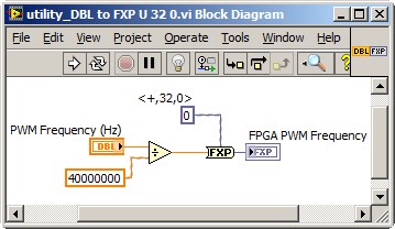
Dealing with the representation of Point fixed and all is a reality for LabVIEW FPGA<= 2011="" programmers.="" you="" might="" build="" a="" small="" sub="" vi,="" such="" as="" the="" one="" attached,="" to="" encapsulate="" the="" frequency="" calculation,="" thereby="" abstracting="" the="" conversion="" formula="" and="" fixed="" point="" data="" type.="" you="" can="" adjust="" the="" properties="" of="" the="" floating="" point="" input="" control="" to="" accept="" only="" valid="">
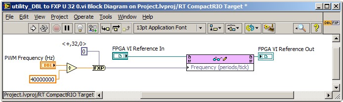
This implies the series VI void on the host of the RT, and not on the FPGA target. So, you also need nodes in the Palette of the FPGA Interface to send PWM fixed Point RT frequency to the FPGA. The complete solution of frequency may resemble the following. It is common for FPGA programmers to build a collection of thesesub screw, that make up the API for hardware.
Note that 40 MHz is hard-coded. For increased flexibility, consider making the FPGA clock rate an entry to the Subvi with a default value of 40 MHz.
-Steve
-
Connect mercury 3500 to NI 9401
Hello
I'm trying to connect mercury 3500 encoder to NI 9401. The pinouts are confused and any help is appreciated. Here's what I think should work, but I'm not sure.
Encoder AXIS AXIS OR 9401
4 1
5 14
9 16
10 3
14 17
15 4
ExcelX salvation,
Currently, the connections of the two instruments together is performed as indicated in the attached connection_diagram.png
I'm not too familiar with 3500 of mercury but think you have to connect pin 9 (mercury 3500) to pin 3 (OR 9401) and 10 (mercury 3500) PIN to pin 16 (OR 9401) to ensure that all of your negative terminals are connected to the Terminal on 9401 com also need ensure that the two instruments share a common ground then you must also over the pin 1 or PIN 13 on mercury 3500 on the NI 9401 ground.
Maybe you are looking for
-
No sound notification since the 2015 upgrade...
I can choose the individual sounds to the e-mail and messages + but I never hear them when an email or text Message is received. I have not had any problems until an IOS 8 update. I hate that, especially since I paid for one of these sounds. Any sugg
-
Qosmio X 300 - 14U - can't find not all USB devices
My Qosmio X 300 - 14U can't find my USB Kingstone Datatraveller, Storejet. Any help please.
-
2 questions: autonomy and recovery
Hello I am considering trading in my iPod 5th generation for a 6th gen, since I've had for almost two years and have come to understand in the last month or two that there more much battery capacity (it lasts almost an hour and a half playing music f
-
Microsoft wireless keyboard and mouse receiver 5000
I bought a combo keyboard and mouse 5000. The mouse never worked good to go, I bought a separate Microsoft Wireless Optical Mouse 5000. The keyboard does not work with this receiver, I'll have to keep plugged in as well?
-
Keyboard, type the letters wrong when you play
When I start a game on my computer without running as an administrator, he begins to act really weird. All the letters stop working. That would happen, that if I press q, he's input 1. If I have another letter of the alphabet input, it will correspon