channel "1 + 2 + 3/2 ' o/p should be 3"
Declare
v_cnt number: = 0;
v_char varchar (20);
v_cha varchar (20);
v_chcnt number: = 0;
tot number: = 0;
t number;
Begin
v_cnt: = Length (regexp_replace ("1 + 2 + 3/2 ', ' + [or] ',' '"))-2;
For i In 1... v_cnt
Loop
v_char: = substr (("1 + 2 + 3/2'), i, 1);
If v_char = ' + '.
Then
v_cha: = v_char;
On the other
v_chcnt: = v_chcnt + v_char;
End If;
End loop;
t : =
substr (("1 + 2 + 3/2'), length (regexp_replace (" 1 + 2 + 3/2 ', ' + [or] ',' ' ")),)
(1);
tot: = v_chcnt / t;
dbms_output.put_line (tot);
End;
/
is there any possible to write in another type...
There is no test because did not have even now oracle... Try:
declare
n number;
VARCHAR2 (128) mathematics;
BEgin
math: = ' 1 + 2 + 3/2 ';
run immediately 'select'. Mathematics: ' the double ' n;
Dbms_output.put_line (n);
end;
----
Ramin Hashimzade
Tags: Database
Similar Questions
-
Is 2 x 1 GB memory supports dual channel on Satellite Pro M70?
Hello
I was wondering if I can wquip my M70 with 2 x 1 GB of RAM running in Dual channel mode? Seller is sure it should work, but as I found no info on the pages of toshiba, I would rather confirm here.
THX in advance
Hello
The seller was right. The Satellite Pro M70 supports DDR2 memory modules. These modules are dual channel.
You can upgrade the memory up to max 2048 MB (2 x 1024 MB)Greetings
-
I can't locate all channels with hybrid USB - Equium L100 TV Tuner
Hello
I installed the software and the USB but I can't locate all channels. There is no signal.
Help what can I do?Thank you
TracyHey Buddy
What software do you use to watch TV?
I m not an expert external tuner but most often you will need an application like a MCE (media library) to receive signals and channels.But the first step should be the installation of material success. I think that you have received the software with this external tuner or drivers. So check the installation guidelines and, in addition, you might check if this TV card appears in the device as recognized Device Manager.
-
3 voltage/current measurement channels, crosstalk between channels
Hello
I am running a NOR-USB-6211 is connected to an instrument that runs labview 8.5. What I want to do, it's current 1 and 2 channels of voltage measurement channel. All are separate physical channels. I use an express VI to separate the 3 channels on the box USB-6211 and trying to draw on maps of distinct waveform stacked in a way that it respond independently (as they should be physical separate circuits). I can ALMOST that it works. I can measure the current very well. The problem is with the tensions. If I change the voltage on channel 2, channel 3 meets both equally (eg. increase 5V on channel 2, channel 3 increases of 5V); However if I change the voltage on channel 3, channel 2 does very little (such as increase of 5V on channl 3, ~0.05V increase to channel 3). Not the best result, but better than the reverse. Channel 1 is not affected by changes in voltage, but it affects the Channels 2 and 3 (current increase, increase of tension of channel 2 and 3). I have no idea why this is happening. I saw the same thing when I used only 2 channels (current and voltage). When the current (channel 1) is changed, the (channel 2) voltage changes, but when the voltage, the current does not work. There must be a problem with the program because I get the same behavior when I physically disconnect channel 3 (for example, always responds when I change the voltage of channel 2). It seems like it should be a simple installation and a simple solution, but I can't understand it.
I've included a snapshot of the program. I share the channels so I can selectively save some data in a file. I tried to simply connect the VI express to a graphic, and does not either (tensions influence each other). I also tried to replace the cluster with a table, but that did not work or the other. I tried to simulate the data with sine waves and I can get this to work without problem. I don't know what I can do.
Thanks for your help.
The f
interference of signals of high-level signals at low level is normal with inputs high impedance of a multiplexer.
put a short channel shorted inbetween and measure this also but throw the zero.
-
Place the data of multiple channels in the tables
At this moment I have a sample program with a value of 8 data channels of my USB-6009 spitting in a graph of a waveform, which looks and works very well. Ideally, I would like to take this data and manipulate it to produce two calculations before it comes out on the graph. After I would handle that I want to display on a line chart (cloud?) as two lines of updated permanently. I think if I can get my 8 channels in 8 separate tables, the rest should be put in place.
Thank you
Hi Iwild,
How you import your data? You place data in a table in a first time?
You use NEITHER-DAQmx? If so, please see this document that goes over how to use NOR-DAQmx with text-based environments.
Best regards,
-
NEITHER 9207 reading current and voltage at the same time channels
I have a cDAQ-9178 chassis USB-three cards NI 9217 RTD, three cards 9263 0 - 10V and one the output OR 9207 16 channels analog card. What I m trying with this kind of things, is to read all the analog input channels (information of transducer, temperature, pressure, etc.) and adjust my controls to process with the analog output channels.
My problem at the moment is the following:
When I create tasks with DAQmx VI:s, how to create a task that reads current and voltage on the 9207 channels at the same time?
When I created a task for RTD-channels (16), a task for the outputs analog 0 - 10V (12), a task for the analog input 4-20mA (8) and a single task analog 0 - 10V input (8) I get an error-50103. I think it s because the tasks of current entry and voltagge are trying to use the same CAD at the same time and LabVIEW informs that "The specified resource is reserved. Tasks are to leave so that the analog output task starts first, then I merged all clusters of the error and the rest of the task are started by an order to current input-> input-> RTD input voltage. I get this error after the current enter task started and enter voltage task begins.
Because I m new on the LabVIEW and stuck in that time, I wanted to try the forum to find answers. I tried to find if someone else was having the same kind of problem, but with a quick search, there was none. I m in a bit of hurry, so I apologize if West a subject with a happy for that and I missed too much according to me.
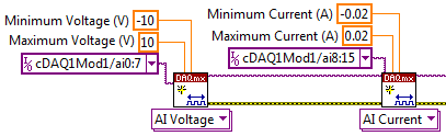
Really, the best way to do it is just adding 8 channels of voltage at a task, then 8-channel current, somewhat like this:
Then spread over different channels when you read later:
It should run without error. It always is multiplexed to sampling, but it will be much faster to create two separate tasks. There will be between 2ms (mode high speed) and 52ms (mode high resolution) between each playback channels, but it will still be much faster than the permutation of the tasks.
-
How to configure multi analog channels inputs in a single task
Hello I want to acquire two signals of the two channels (input 1 analog acceleration; analog input voltage 2) without using wizard DAQmx because I have to use standard vi I use usb NI 9234 any suggestion please I tried with a chanel and I got good result but when I try two delivery channels I errors please hep me
Hi Broutchoux,
What are the errors you get when you run your code? This is a mistake-50103? As long as your acceleration and your task of voltage use the same synchronization settings, you can combine the two channels in a single task. This should fix the error you receive. The article below has a picture that shows the configuration I describe:
With the help of different Types of Global DAQmx channels in the same task
http://digital.NI.com/public.nsf/allkb/3296BA2AEF586B7386256D6D00528E3D?OpenDocument -
What is the best way to change this program and to read 1 sample of each channel?
The initial program was conducted with NOR-traditional DAQ. I change it to DAQmx the best I could. The program, he is already the application of voltage to generate code (Daqmx Write.vi). But I have problems with the acquisition of tensions, give me readings rare (Daqmx Read.vi) I don't know if I have to make a (Daqmx start Task.vi) for each channel in the program or if I can make it work with a single. Notice I have no significant changes a lot because this program is already running in another lab, and they send us the program so we had no problems so much but rather than get the BNC-2090, they got the BNC-2090 is who uses DAQmx instead of the traditional. If anyone can help?
A BNC-2090 is just a connection block. It has no effect on the question of whether you should use traditional DAQ or DAQmx. Which is determined by the DAQ card that you are connected to the terminal block too.
You can refer to this document, differences between the BNC-2090 and connector BNC-2090 blocks has, but it's just saying to change the label of the Terminal Board to reflect the new DAQ cards.
What problems are you having with the new VI you just posted? You get an erro rmessage? I don't know what mean "rare readings.
You really shoud look at some cases DAQmx in the finder of the example. Some problems that you are experiencing, is that your blocks of data acquisition are all kinds of disconnected. Generally, you should connect the purple wire from your work function of creation, through the beginning, reading or writing, then the narrow task. Many of your data acquisition functions are sitting there on the small islands now. You should also connect to your son for the error.
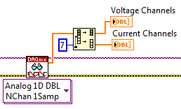
With DAQmx, you should be combining all your analogue channels in a single task. It should resemble Dev0/AI0... AI7. Then use a sample of channel 1 N DAQmx read to get an array of the readings, you can then use array of index to break.
Other things you need to do is to replace the structures sequence stacked with flat sequence structures. Turn on automatic growth for some of your structures such as loops. At the end of the day, you might find, you can eliminate some of the structures of the sequence.
-
I am a new user of Labview and have some problems. The main question that seems to be involved, is that when I put several input channels (dev1/ai17, dev1/ai18...) to record in an excel file, the number of samples per channel changes according to put them only one channel of input. If I don't have that one selected channel program records temperatures all 0.5seconds if I put more than 1 program collects samples every ~ 10ms. trying to get several input channels to take 1 sample of each channel each specified frequency (ranging from all s.5 to 2 sec). I do relize that this code can be nice to look at, but someone could suggest a few ways to conquer the problem?
User of LabVIEW 8.
For the acquisition of a single sample of several channels in some cases, the code below should be close to what you need. The rest of your needs I'm not sure that I understand and I'm not familiar with the screw Express you use.
-
Satellite A105-S4344 - DVD playback is slow & audio is choppy
I'm having a problem with DVD playback on my a105-s4344.
DVD playback is delayed, slow and audio is choppy and delayed also.
BUT the movies that I play through iTunes work well, those who are bought and on my hard drive.
It only occurs with DVDs I try to play in any program I try to play the movie.
I tried several movies, new, old, burned, bought, etc.
All the same problem.
Help. I don't know what to do.
Hello
If this delay seems to play only the movies and audio by using the CD/DVD drive, then you should check this short work around:
1) access Device Manager
(2) expand the IDE ATA/ATAPI option
(3) go to the primary IDE channel-> properties-> Advanced settings
(4) here, you should check if DMA if available has been chosen
If it s not set to DMA if available, then remove the primary IDE channel of the list of devices and reboot the laptop.
After that the laptop has started again, check again the single point and check if DMA if available appears againWelcome them
-
Desktop HP Pavilion p6210y PC: RAM install problem
My office is in the factory with the exception of the video card which is a NVIDIA Geforce GTX 750Ti graphics card. I bought by 4 chips of RAM DDR2 PC2 6400U 800 MHZ 240 PIN by Samsung and installed according to the instructions from HP. I also double checked my bios and updated to the latest version that has been on the HP website on 20/05/15. When installed and rebooted my computer I first had a problem with my computer freezing completely on my and I have to make a difficult stop by disconnecting the tower. I did a reboot and done a diagnosis (F9) and waited to see what would do the memory. Initially, I had a 'FAIL' BIOMEM-1 error. After a few attempts, I then is gone one chip at a time and done the same thing. After that the first 3 installs successfully, I determined then a single chip was bad. At this point, I restarted my system and started running it with 12g of RAM. After about 10 minutes, my computer froze again and went to a blue screen stop. After that restart the desired system get a dskchk is for windows. I've looked online and made a Windows hotfix, and cured this problem but continued to get the gel and closed blue. I then reinstalled the factory RAM chips, and it is not reappeared since. According to all that I can see 3 of my chips are good and should run. What other steps could be or are at - it a driver for updating bios them or not, I have to do? Help, please!
Only using three DIMMs will force the PC to run in single channel mode.
Your first consideration should be Support HP or HP sales during the consideration of upgrades or replacement of memory. If you want to consider other manufacturers of the best way to avoid memory problems is to contact one of the leading manufacturers of memory. I would recommend that you try the tools of these manufacturers: Corsair, Kingston andCrucial. Once you have determined the DIMMs that you need, then contact commercial or technical support to check that you have selected the correct DIMMS. If you buy directly from manufacturers, then they will stand behind their products.
-
Hello
I am trying to create a use for reading .txt files. The values of each channel are arranged in rows (lines in the txt file). The collums are separaded by the tabs.
I can't figure out how to set the layout of data in DIAdem 2015 s use Wizard.
Here's a quick example:
# #EXAMPLE. TXT#################################################
#Header - ignore this line
value0_1 value0_2 value0_3 value0_4
value1_1 value1_2 value1_3 value1_4
# #EXAMPLE. TXT#################################################
I want that all the value0_x in the channel 0.
All the value1_x should be in track 1.
I hope you understand what I'm looking for.
Thank you in advance!
I don't know if it can be configured in the wizard, but it can be written in a few lines.
Save this code in a new created use. (Parameters-> Extensions-> Dataplugins)
Option Explicit
Void ReadStore (File)
File.Formatter.Delimiters = vbtab
File.Formatter.LineFeeds = + "\n"
file.Formatter.CommentSign = ' # '.protected groupObj: set groupObj = root. ChannelGroups.Add ("group")
do
protected chObj: set chObj = groupObj.Channels.Add ("channel_" & groupObj.Channels.Count, eR64)
Dim nextVal: nextVal = File.GetNextStringValue (eR64)
Dim i: i = 1
isempty (nextVal) while not
chObj (i) = nextVal
nextVal = File.GetNextStringValue (eR64)
i = i + 1
Wend
Loop until not of File.SkipLine
End SubMust read the files of the form
#Header - ignore this line

0.1	0.2	0.3	0.4

1.1	1.2	1.3	1.4

2.1 2.2 2.3 2.4 -
Maximum value such as a number or a string
Hallo,
I calculated the maximum value of a channel. The next step is to use this value for further computation. My problem is that I can't use this value as a number. It is just a string. I tried with
ChnPropGet then I got the number. But I can't use it for calculations. Anyone have an idea how I can fix this problem?
I've attached a screenshot of my script. I use the German version of 12 DIAdem.
Thanks for the help...
Hello LePot,
the properties. The function returns the property in its native type. If you navigate to the maximum property of a channel, it will return the value as a floating point number. You can check this by running the following script:
(The script assumes that the dataset example is which has a number of Group 3 with a channel named "Res_Schall_1". But your chains should give you the same result with the message box showing "double."
Dim Maximum
Maximum = Data.Root.ChannelGroups (3). Channels ("Res_Schall_1"). Properties ('minimum'). Value
MsgBox (TypeName (Maximum))If you ever want to convert a number represented as a string, be careful when you use "CDbl". This VBScript function assumes that the number is formatted by using the language of oyur BONES, especially the decimal setting (in '. 'or', '). If the setting of the operating system does not match the way the number is converted to a string, you have a problem. That's why the offer DIAdem::Str() to go a certain number to string s and Val() to go the opposite direction. Using CDbl can create rellay average errors that are difficult to detect.
Andreas
-
acquisition of simultaneous generation of 6555
Hi, we strive to get data in and out of a map 6555 to/from our associate DEGREE, which is connected to the map of 6555 via the provided wiring and LabView with the manual VI tool which allows to control the map sample data, the wiring is correct (confirmed the scope).
However, when we run our automated program that is supposed to load our data files and send them out, we don't see no signal at all on the same PIN that we led with manual tool of VI.
How our hardware guy wired the Board upward is kind of arbitrary (some channels are entered, some are out and not in a particular order or organization).
As a beta test, we start with channels mapped to the acquisition of DIO0-DIO15, and DIO16 mapped to the generation. There is an HWS file, I created and which contains the data flow for DIO16, and then we want to save DIO0-DIO15 while DIO16 sends data.
However, we do not see the data coming out the wire again.
Two main issues:
(1) what string values should we be turning to niHSDIO_AssignDynamicChannels() to put in place the channel like that assignment?
(2) should we padd strings in the data file that we send to niHSDIO_WriteNamedWaveformU32?
I was wondering if the data we are trying to send to DIO16 maybe DIO0 or something.
Thank you.
Ed
Since you're using the U32 write, it means that writing VI expects an unsigned integer of 32 bits, with each bit associated with an output of the 6555.
So for output to line 16, you could Pad the 16-bit integer. (Basically of output hex 0 0001 0000 x corresponding to 1-bit followed by 16 zeros).
-
Progress of asynchronous data TDMS wrote for LabVIEW RT
Hi all
I save data in many channels TDMS files.
Data record should be done on a real-time target OR SMU 8135 with LabVIEW RT operating system.
The data of all channels of the recording in a cycle time of 1ms.
Question: What Advanced TDMS mode should be better suited for this task? Sysnchronous or asynchronously?
It seems that the advanced TDMS asynchronous logging is not supported by LabVIEW RT? Is this true?
Thank you.
Rahul
Hello Rahul,
Advanced asynchronous PDM are not supported on RT.
Best regards
Christoph
Maybe you are looking for
-
This is what exactly gets moved with directory change & organize?
Hi all Quick question because I am about to install my SIN: I decided to put my iTunes Media on my NAS drive folder, but I will keep everything (files to iTunes library, Album art files, etc) on my local computer. My question is: when I go into my iT
-
My sub - VI does not work unless it is open
I'm working on a simple data analysis program for a system for the acquisition of 32 channels operating at 2 kHz. Before opening the > 50 MB .csv files, I would like to chart to see what was going on in each channel, on a graph (i.e. 32 series plotte
-
Compaq Presario cq57: disabling the bios system (63050043)
Cannot access my bios, I get the system off when you try to startCode: 63050043
-
DVD player doesn't work after installing SP3 for Windows XP.
DVD player doesn't work after installing SP3 for Windows XP. That it disappeared from "MY COMPUTER". Device Manager sees it, but there's a yellow exclamation mark over it. See the BIOS of the motherboard and it still works in the BACK. I know SP3 is
-
error message internal battery hp dV6 - 1263cl
Every time I start my hp dV6 - 1263cl I get an error message telling me my internal battery may need to be replaced, where can I find an and how do I install it? Thank you