Chassis & 10GbE blade M1000e through Modules
We rotated M620 blades with 1 GB Pass Through modules without any problem. The M620s have the Qlogic\Broadcom cards mezzanines KR 10 GB for slots chassis A1\A2.
We have just bought a few Pass through modules of KR 10GbE and exchanged out them. in the same locations of A1\A2. When the configuration of the BIOS, we get green link is turned on with our Cisco Nexus switch which shows a connection on the port, but when ESXi6 is loaded there is no link (orange light just on the module). NIC in ESX is set to automatic (will not force the 10 GB according to VMWare).
Tested updates, driver updates, change cables Twinax Dell SFP + and fiber but no link. If I put the 1GbE modules back in they work fine.
Strangely, at one point I did get network link in ESX running a single passthrough but have not been able to recreate it. Am I missing something that I do not see a reason for this which is why they should not work? This chassis we test on is quite old (2008) and we use just to test before deploy us in our new M1000e chassis. What is the material inside the frame at the origin of a problem that has subsequently been updated?
You should be fair exchange in the chassis with the median plan 1.1.
Tags: Dell Servers
Similar Questions
-
update firmware on chassis battery blade PC8024-k?
I tried to update the firmware on a stack of switch PC8024-k 2 5.1.5.1. After the update, this is what I get:
Unit image1 image2 current-next active
---- ----------- ----------- -------------- --------------
1 5.1.2.3 5.1.5.1 image2 image2
2 5.1.5.1 5.1.2.3 image2 image2According to this table, unit 2 will start the old image the next time that it restarts; How can I change?
I think you will find your answer in the section upgrading the firmware of the stacking for the M8024-k Guide, page 43.
Unit image1 image2 current-next active
----- ------------ ------------ ----------------- -----------------
1 4.2.0.1 4.2.0.2 image1 image1
2 4.2.0.1 4.2.0.2 image1 image1
3 4.2.0.2 4.2.0.1 image2 image2
4 4.2.0.1 4.2.0.2 image1 image1
The current active column now displays the same values as the next column is active. The next step is to
activate the image that contains the new firmware. In this example, the units 1, 2 and 4 shall
will active image1 Image2 active and unit 3. Run the following commands.
Console #boot system 1 image2
Activate image image2...
Console System 2 image2 #boot
Activate image image2...
Console #boot system 3 image1
Activate the image1 image...
Console #boot system 4 image2
Activate image image2...
Here is the link to the article: http://bit.ly/WQOc2h
I hope this helps.
-Victor
-
A fabric mismatch detected C mezzanine card
Hello
We have chassis blade M1000e with modules passthru "DELL 10GbE XAUI PTM" and several blades work M710 with 'Intel 10GbE/FCoE double X-520 KR' NIC in fabric C.
Now two new knives M620 with NIC 'BOUZHAM 10GbE 2 p 57810S - k Mezz' fabric C have been installed in the chassis, and I am unable to turn on, get the error:
HWC2008: A tissue mismatch is detected for C mezzanine card.
Detailed description:
The fabric for the cards of the IOM and the mezzanine type must match. Once a card IOM or mezzanine is inserted into the chassis, the type of tissue is then set to the MCC and CMC will ensure the continuation of IOM and mezzanine cards match.
Recommended action:
Check the chassis type of fabric in the GUI of CMC and compare the type of card the IOM or mezzanine.
Does this mean the Broadcom 10 GB NIC are not compatible with the passthru module?
Thank you!
Hello
According to the matrix of support only the support10GbE cards listed XAUI PTM.
Since it is a different protocol 2 XAUI vs KR, broadcom could not establish the link due to the backward compatibility.
Dell 10 Gbit Ethernet cross II supports XAUI following cards:
Broadcom 57710 mezzanine card
Broadcom 57711 mezzanine card
Intel X 520 mezzanine card
Card mezzanine Intel X 520-x/k
QLogic QME8142 mezzanine card
Emulex OCm10102-f-m mezzanine cardhttp://www.Dell.com/us/Enterprise/p/Dell-Ethernet-PassThru-10gb/PD
Concerning
Karta
-
Hello
We plan to buy TL2000 FC - LTO5 with double Tape Drives, trying to get it started I noticed there are two FC ports at the rear of the chassis TL2000.
Do I have to connect the two FC ports with LC connectors to my SAN switch or will an FC port?
My SAN switch Cisco MDS 9148, server is m620 with 2572 MEQ. My chassis has 8 FC through modules.
Thank you
Paul
Hello Paul,
2 ports at the back of the drives LTO5 is just in case a port dies, you can use it. You can connect just using 1 port as if you were to connect the two ports you would use only one at a time on the TL.
Please let us know if you have any other questions
-
Module number 9222 compability in 9144 chassis
I'm running a cRIO-9025 system with additional 9144 chassis. After a 9222 module in the 9144 chassis, I found it wouldn't work. I checked the Web sites NOR and found a table were it appears that this combination is indeed not taken in charge. This will change in the future? Is it possible to use it in the cRIO 9114 chassis? When I tried, it said that it only works in FPGA mode while I was using this SCAN mode. As far as I understand this SCAN mode is necessary for the 9144. So, I was wondering if it is possible to use the SCANNING-only mode for the 9144 and FPGA mode for the 9114 and if so, how?
I'm very new to all this, an explanation of the novice-friendly or a link to a good paper on this subject would be much appreciated. Thank you very much!
-Yes, you can use scan modes for the 9144 and FPGA for the 9114. It's the way you need to set the project that the 9222 is not supported in scan mode.
You don't have to do anything special to do that work, just set up the two chassis.
We try to get all the module in scan mode, but due to performance issues, don't support not all c series modules. We constantly re - evaluate which modules we support - I'll make sure that your comments on the 9222 happens to the development team.
-
How do I move the UCS with OS blade on the local disks between chassis
Hello
I have to move the blade between chassis - blade have OS installed on local disks and Associates profile.
I can simply:
Shutdown
Enter the maintenance
remove the chassis
Exchange with other blades of the second chassis
power on
Blade are properly recognised and profile will go with it?
I found Advisor here it is best to unassign blade profile and partner back after removal:
https://supportforums.Cisco.com/discussion/11230671/physically-move-Blad...
but it seems too complex for me - if someone who tired of this exercise can share some experiences?
See you soon
Hello
Assuming the frame belong to the same domain (even pair of fabric for interconnection) and you are using ESXi, try the following:
1 - Enter the host in maintenance mode (it can be move virtual machines to another server/power them off / take them into so maintenance mode)
2. cut the blade
3. ensure that the Service profile does not have a disc of scrub policy so that data is not deleted when the profile Service (SP) is ungrouped
4 separate the SP
5 decommissioning of the blade
6 - Remove the blade and insert the new blade
7. move the second chassis original blade
8 - though the blade and an associate of the same/original SP
9 powers on the blade
10. take the server out of maintenance mode. as well as virtual machines
Note: For the blade inserted in the drive, that we released our blade, you can create a new SP and pair with it or you can actually have any MS (including that attributed to the recently released blade) and assign it to the new blade.
A single SP by sever and that one server per SP.
SPs are independent from the hardware (as long as the material is compatible with the functions set up by the PS)
Let me know if this info has helped, if not let me know and I wil expand or try to make your job easier.
Please note ALL useful answers
-Kenny
-
Variation of thermal EMF of the PXI-2530 modules
This message/question is a companion of my the most recent message in another thread.
In addition to watching some resistance higher than expected that affected current measurements using modules PXI-2530 multiplexer 4W topology, I saw systematic variation in track-to-track blood pressure measurements. Tensions would increase gradually through the 16 channels in a configuration by measuring the voltage at the terminals a resistor 1.5 kOhm with 0.5 au crossing (75 uV). I've identified that the thermal EMF of the reed in the PXI2530 module switches is on the same order of magnitude of these measures and set out to quantify the differences EMF thermal track-to-track between my three modules.
Test method: I have a TB-50 which is configured to mux the signals of tension for a DMM. I connected each of the four DB-50 one cable of 176 pins to this block and collected with a PXI-4071 pressure readings set to 7.5 digits precision in the range of 100 mV and > 10 GOhm impedance. For most channels, it took several minutes for the voltage stabilize - or at least appear that it was to stabilize.
I enclose three graphs. Note that the vertical scale is the same on each.
Data that triggered this survey was collected with MUX1, via connector P2 to voltage. The magnitude was not quite the same-probably related to the phenomenon of stabilization time, but obviously the worst group of channels three multiplexer modules.
The three modules were all bought at the same time (about 2 years ago), but had only limited its use in the first year or more. The three now have various 'mileage' based on my use. But MUX1 clearly behaves differently two other modules. The
I changed my test conditions to spend 0.5 au via a higher resistance to thermal EMF less important. The PXI-2530 sheets indicate that thermal EMF must be less than 50 uV. In most of my measurements, it is. But not for MUX1!
Any thoughts?
Thank you
Jeff
Hi Jeff,
You can check that all the three modules are PXI-2530, not PXI-2530 b (while, as the PXI-2530 b parts slightly higher thermal emf)?
Specification of emf thermal 50uV of the PXI-2530 is a typical value, is not a guarantee of spec. See a few channels higher than the spec is not a cause for alarm, but it shows that we must take account of this in our measurement error. Note that the industry standard for the technical measure thermal emf is to close the relay, wait a few minutes and then take a measure of tension. For example, if you scan through a switch faster than a relay per minute or so, the thermal emf will be less predictable and stable. A single module performs worse at these low voltages is not indicative that this module is a failure, etc. the module is fine. Unfortunately, the reed relays have more emf thermal relay of the armature, mainly because of the many layers of metal in a Reed compared to a frame (each metal junction is a source of emf if these metals are not the same).
Thermal EMF is proportional to the temperature, it may be interesting to note the position of the chassis of the less powerful module. Placing hottest modules (scanners, Ara, RF, etc.) will reduce the thermal emf.
-
Firefox closes in response to halfway through loading a page using Windows 10
I tried both 40 and 42 version. Whenever I try to load a Web page, Firefox closes responding to half way through. I went through modules. I went through all the articles help and nothing has worked. The problem started after I installed Windows 10 and often happens on Politico and Fox News. I tried to uninstall and reinstall. After uninstalling, I scanned the registry with ccleaner
I think I have set myself. When I started this evening I had the option of updating Firefox. After doing this, everything seems to work properly. Thank you
-
get the MAX to recognize the SCXI modules
Hello, try to keep it short, we strive for Labview 5.1 running on the XP machine, until we get new set kit to date in the future (current NT machines fail). I tried NiDAQ 7.1 8.1 drivers with a PCI-MIO-16-4th card in a Dell optiplex 755, and the current sticking point is to configure the system via MAX to specify the type of chassis and modules. Modules are not found automatically, and entered manually the results into the slots being declared empty, on a test of the chassis (chassis SCXI-1001). SCXI modules we are SCXI-1100, SCXI-1162HV, SCXI-1124 2 x and 2 x SCXI-1160. What should I do to make this work? Different driver? I'm not at all familiar with the inner workings of Labview! Thank you.
Rob,
Thanks for the reply. The problem was more the cable SCSI detaches from the end of SCXI chassis (these connections seem very inclined to come drifting). The modules then self populated, and the system works now. The system worked very well for ten years, but the old Compaq PC fail now and we have only a few replacement Dell, but of course they come with Windows XP, while the ran Compaqs WinNT, it has so been interesting trying to get Labview 5.1 running on the new boxes with the old cards DAQ until we get funding for new cards / Labview 2010 / Teststand. Problem solved for now!
-
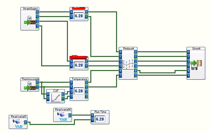
DASYLab Lite, CompactDAQ Ethernet, "the stream blocked by a later module" error
I receive the message 'the stream blocked by a later module' and then the execution stops. I tried to remove the modules without change. He usually stops 8 minutes, 20 seconds (500) in the race. It happened on two different computers (same network, however). How can I get my program to run longer (forever?)?
I am using a cDAQ NI 9188 (CompactDAQ Ethernet chassis), NI 9237 (strain gauge module), NI 9211 (thermocouple module), OR-DAQmx 9.5.1 and DASYLab Lite 12.00.01. My program of DASYLab affect strips from 100 Hz sampling frequency. The calculation of the average (reduce) block performs an average arithmetic with the size of the interval of 100 and a block size of output of 1.
Thank you!
Which module complains about being blocked? Look at the title bar of the message - it should show the name.
You can observe the locking by turning on pre-trial block view-Animation-FIFO.
I am suspicious that average organizes blocks more were awarded.
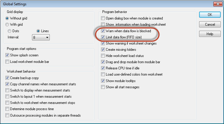
One thing to try and really monitor your computer after doing this...
Go to the Options menu in the spreadsheet view, then open the General preferences. Change these two settings - see the image - turning them off. The risk is that your application uses too much memory, so, please, provide oversight.
-
Hi all
We have NI 9421 digital input and digital output NI 9472 Modules. We can run these modules into a VI under the 9073 cRIO chassis. While we have added the FPGA target under the same chassis, we cannot use the modules. We also install the scan engine.
How can we use FPGAS and i/o Modules at the same time?
Once you add a target FPGA in CompactRIO chassis, when you deploy the code, the cRIO is configured for the FPGA mode, which requires a bitfile compiled to connect with the C Series modules. Remove the target FPGA or changing the mode of chassis in the project and by redeploying must reconfigure the cRIO for scan Mode, which allows you to use the IO module directly from the RT VI.
For more information, see this post.
-
I tried to configure a target 9067 cRIO. I have properly configured unit (last RIO drivers and firmware 2015...).
My problem is when I create a project, I can see and connect to the target, but I see the chassis without any number or modules.
I can see the modules in Distributed System Manager and they give the eigenvalues, but nothing on my project.
I appreciate all the help with this isse confusion.
[Note: when I add a target to my project I don't get FPGA/Scan mode selection window]
Sounds like something was wrong with your installation of LabVIEW 2015 - have you installed LV2015 after the drivers? If so, support for the development of the LV2015 would not be installed - I would try to repair/reinstall the drivers.
-
Scan engine mode on RT does not not with EtherCAT NI 9144 chassis
Hello
I have problem with communication of the cRIO-9074 RT with NO 9144 via EtherCAT.
I add the expansion with a NI 9203 module chassis to my system running on the cRIO-9074.
I use it in engine scan mode. My PC application communicates with RT by network data stream. When I run only asks to RT, the RT is the reading of variables EtherCAT I/O chassis with no problems, but when I run the PC host application, RT probably go into configuration mode and interrupts communication with chassis EtherCAT - I can see that the LAN LED on expansion chassis stops flashing. "" Then, with still running application I click in the LabVIEW Project Explorer, the item target and select utilities ' Mode Scan Engine "pass back"Switch to active"Configuration, then it starts to communicate. I tried to do the same thing programmatically work with the Scan Engine VI Mode Set but it doesn´t so Runt-time it does not work as well.The behavior described above happened when I added the chassis extension in the project and only the module place entries in this chassis are affected, the rest modules 8 places directly in the cRIO-9074 work withou any problem.
System:
Professional Win7
LabVIEW 2013 SP1
OR-Industrial Communications for EtherCAT 2.7
OR CompactRIO 13.1Hello
problem solved. The reason was function RT Set Date and TIme.vi what casues on NOR-9144 error and blocked EtherCAT communication. I found that this function is no longer supported in LabVIEW. After the removal of this feature of application of RT, everything works fine.
BR, Jan
-
9211 module and IR thermocouple
Hello world
Once more I need a little guidance from the community. I work on a new device and uses a cRIO-9074 chassis with a TC 9211 module. I'm trying to connect a mini IR thermocouple (link below, OS36SM-K-140F part number) for one of my measurements. The part of my camera, I'm trying to measure, I can't do a physical contact with. Supposedly this TC IR reads like a type K thermocouple, it works fine on my player of TC 52II Fluke. When I attach to the 9211, I get a much higher reading is accurate, around 60 ° C when the regular TC I compare to claims 24-25 ° C. I tried to play with the edge scaling factors but could not get an accurate reading. TC IR must be able to read between 20 - 90 c with precision. I noticed on the datasheet that there a high impedance which may interfere with some readers. This would affect the 9211? Any help or advice here would be much appreciated.
http://www.Omega.com/ppt/pptsc.asp?ref=OS36SM&ttID=OS36SM&NAV=
Kind regards
PChemist
Hello world
I managed to find a solution to the problem I described above. It seems that a C a cRIO Module has a problem adding a scale as the DAQ Assistant does not work. My solution is in the picture below. I compared it to a calibrated thermometer, and it's better than the standard deviations of a typical K type thermocouple.
Kind regards
PChemist
-
Is the 9178 chassis limited to a 9213 module? I am trying to install two and only appears in Measurement & Automation.
I have contacted support and a service request # now. Thank you
Maybe you are looking for
-
Windows Movie Maker - savings-older version
HI - my daughter received a project to make a band trailer of the movie using Windows Movie Maker. We have 6 Version, no problem. But the school has V2.1.4026.0 with a Spk2 V5.1. The teacher said that we have to save the project, so it can be read
-
Is it possible to use AD EHT admin accounts? When I choose an admin account and click on external, I don't see the option to use the ad as being the source of identity. With the help of ISE 2.0 Thank you
-
Windows media player not funziona ho windows 7 original
Windows media player not funziona non riesco ad aprirlo ho windows 7 original vista, my non so come fare. Ho downloaded mesh e funziona tutto pero quando voglio although he player music mi dice che ha di funzionare then e windows attempts una soluzio
-
are adobe cs6 yet and adobe media encoder cs6 are the same thing?
are adobe cs6 yet and adobe media encoder cs6 are the same thing?
-
Animate 20141 - 100 %w CC & 100 hour no longer works for symbols
Hello.I experienced something strange in the last update to animate dashboard. Before it was always possible to put a symbol for the width and height of 100%. You need to enter the symbol and then set the height and width in %. He later worked at the