9178 chassis to a 9213 limit
Is the 9178 chassis limited to a 9213 module? I am trying to install two and only appears in Measurement & Automation.
I have contacted support and a service request # now. Thank you
Tags: NI Hardware
Similar Questions
-
9237 & 9205 with 9178 chassis sampling rate problem
I have two 9237 and installed 9205 on 9178 chassis. In order to acquire data at the same time, all the 9237 and 9205 use the 9178 chassis onboardclock. But when the sampling frequency is 20000 Hz, 20000 points just takes less than a second. When the sampling frequency is 10000Hz, get 10000 points takes 1 second. Why does this happen?
A 9237 use a channel, another 9237 use 4 channels, the 9205 use 3 channels (differential). And manual brand 9178 slightly confused me, the frequency of onboardclock MHz 80?
Looking forward to your help. Thank you.
By default the 9237 derives its clock dividing down from his own time of 12.8 MHz (see specifications) base.
12.8 MHz / 256 / N
Where N is a whole 1 to 31.
10 kHz is achievable (12.8 MHz / 256 / 5), but it's not 20 kHz (12.8 MHz / 256 / 2.5).
The driver will round up to the next frequency, which is be of 25 kHz (12.8 MHz / 256 / 2). 25 kHz, we would expect 20 k samples to be acquired in 0.8 seconds.
Best regards
-
Bad analog output help Every_N_Samples-NI-9263 cDAQ-9172 chassis (works with cDAQ-9178 chassis)
Hello
The NOR-9263 analog output voltage geberation works correctly with the cDAQ-9178 chassis but gives wrong result using the chassis NOR cDAQ-9172.
In the attached code example, a single cycle of a sine wave is composed of 40000 samples and came out in the background using Every_N_Samples at a rate of production of 5000 samples per second.
The output buffer size is set to 10000 samples.
Prepare us the buffer writing 10000 samples 1, then write the remaining data in the background using the Every_N_Samples callback.
Bug: Using the cDAQ-9172 chassis, to the 5000 s/s sampling rate with the help of an external field (or through closure to another HAVE), we observed that 1 10000 samples came out twice, followed by the rest of the waveform. The last 10000 samples are never exits. If you are working properly, we would expect to see 1 full cycle of a sine wave.The bug does not occur with the chassis NOR cDAQ-9178. I use the driver NIDAQmx v9.2.1f0 on Windows XP
The bug does not happen with simulation devices, so you will need to use harwdare real to reproduce.Please find attached an example of code C based on the example program OR "ContGen - IntClk.c" to reproduce this bug.
Thank you
whemdan,
The MathWorks
Hi whemdan,
By default, DAQmx regenerate old samples if no new data is available. To give the correct behavior, you can:
Use DAQmxSetWriteRegenMode to disable the regeneration (DAQmx_Val_DoNotAllowRegen). In most cases, this is recommended if new data are written continuously in the buffer as the build is in progress.
If you just need to generate 40 k samples, you can write them just all at once, rather than in 10 pieces of k (the code you attached probably is just an example, so I'll assume that you have a reason to write the data into segments in your actual code).
I think the difference in behavior between 9172 and 9178 can if explained by the different way, buffering is set up on each product. The 9172 uses a buffer of 8 k (on the STC2) in all cases (source). The 9178 uses an 8 k of memory buffer (on the STC3) If you use regeneration shipped, but uses the 127 samples FIFO cartridge, if you use no on-board regeneration (source).
Then... on the 9172 8191 samples are immediately transferred to the FIFO. By default, the hardware is going to request new data when the FIFO is less to fill (this is configurable with DAQmxSetAODataXferReqCond). I'm not sure what the transfer data request size is in your case (you can set the maximum value with DAQmxSetAOUsbXferReqSize), but obviously it is bigger than the other 1809 samples that you have not yet sent to the Board of Directors of your first entry. At this point, the pilot will regenerate 10 existing k samples so that sufficient data will be available to meet the demand of data transfer.
The 9178 however use the FIFO of 127 smaller samples so you will not have the same behavior in your case.
In summary, the behavior is explainable by the difference of material. If you want to avoid to regenerate old samples, you should ban the regeneration using DAQmxSetWriteRegenMode.
Best regards
-
Channels by 9174 and 9178 chassis
I'm trying to figure out the most cost-effective means for the conduct of the digital output channels as much as possible by using one of the cDAQ chassis.
The former chassis cDAQ (NOR cDAQ-9172) contained a specification of 64 digital i/o channels per chassis. I can't find a similar specification to the cDAQ NI 9174 and cDAQ-9178 OR. Are limited to 64 outputs both digital as well, or is limited to half 9174? I can drive 64 lines of digital output with two modules (NI 9476), so the numberslots in the chassis is nowhere nearly as important to me as the number of channels.
Thank you
Matt
Hi Matt,
I think I found the source that lists DIO 64 as a max on the cDAQ-9172: the technical details related to off the Web page. This is incorrect. All the CompactDAQ chassis can support the maximum number of possible digital channels based on their number of slots; 32 channel modules is 256 channels for the 9172 and 9178 and 128 channels for the 9174. You can use 2 modules NI 9476 to control 64 lines to any CompactDAQ chassis.
Please keep in mind that you cannot use timed by the hardware or the characteristics of counter/timer thanks to a module NI 9476. For more information about support for the digital functions on each frame, please consult the document "User Guide and specifications" for each frame, which is larger than the data sheet.
I apologize for the mistake of documentation that you have found, and I spent this long to fix.
Kind regards
Kyle -
new cDAQ-9178 chassis was smaller than the cDAQ-9172 old buffer?
Digital waveform features:
Waveform acquisition (DI) FIFO for cDAQ-9172: 2047 samples
Waveform acquisition (DI) FIFO for cDAQ-9178: 127 samples per slot
This means that the new HW (9178) has a much smaller than the old buffer (9172)!
I want to run a correlation over generation/acquisition at 2 MHz with 2000 samples. Does this mean that the new chassis will not be able to acquire the whole of the data (I use a NI 9401 module inside the chassis)?
FIFO sizes are misleading and not a true indicator of the chassis supporting the streaming is not the single buffer. We did some tests comparing the latest and cDAQ-9172 chassis. You will not notice the difference, especially with your application to a finished task of 2 000 samples at 2 MHz. With 2 000 samples, you can run your DI task on your chassis cDAQ-9178 at 10 MHz if you wanted without problem (don't try with continuous or even finished tasks).
The only time where the FIFO size really comes into play is when you run a primary task at high rates, say > 5 MHz, even if it is system dependent. At these speeds a FIFO that is deeper 2 000 samples you buy only tens or hundreds of additional microseconds when Windows jitter is measured in milliseconds.
I would be very surprised if there is a practical application that worked on a cDAQ-9172 chassis which did not work on newer USB cDAQ chassis.
-
Use PFI0 on Compact DAQ 9178 chassis as input event
Hello
I have a Compact DAQ Chasis 9178, and I connect a 5V input signal.
By a detector detector.I want to use the Signal in Labview. It is possible to convert this signal to a Boolean true or False?
I want to read this signal directly from my VI.
Thank you
If you have assigned your meter indicator in the Subvi to the connector pane?
If you don't know, what is the part of the connector, and then search for 'Connector components, assignment of the terminals' in the help of LabVIEW or look here.
http://zone.NI.com/reference/en-XX/help/371361J-01/lvconcepts/creating_subvis/
If this isn't your problem - you must be a little more specific. How do you want that the main VI to "receive" the data, how did you program it to do?
-
Connect a cRIO-9081 a cDAQ-9178
I want to connect a cDAQ-9178 chassis to a cRIO-9081USB port.
The cRIO-9081 has Windows Embedded 7 on it. I wrote a LabVIEW FPGA program that is loaded in the cRIO FPGA. Once started the FPGA, FPGA ignores basically on the side of Windows, very minimal data exchange.
I want to use the side WIndows to run a program cDAQ. I have to do it this way because the cRIO has 7 modules inside and the cDAQ has 7 modules.
Whenever I insert the 14.5 of NOR-DAQmx CD into a CD drive on the cRIO, I see that the cRIO drivers. How can I get the cDAQ drivers installed?
I was able to work around the problem by copying the DAXmx on a USB and install from there.
-
OR 9401 at starting out a value greater than 4 000 000 000
I use DAQ Assistant to read linear a NI 9401 moving in a cDAQ 9178 chassis. On a few occasions, when I load the VI and start logging from the front position there is no movement, the NI 9401 generates the values as high as 4,294,967,241. He slowly counts down and then when there's actual movement, the 9401starts OR count the position of 0. On other occasions, it starts normally from a position of 0. No one knows what means this high value and why it's output?
johnsold wrote:
A number like who are close the possible extreme values for an I32. I suspect that your negative movement caused a reversal of meter that has been interpreted as a maximum or near maximum negative number.
You are actually at the limit of 32 (32-bit unsigned integer). If the movement back would result in turnover between 0 and 4294967295 and slowly down while moving backward.
-
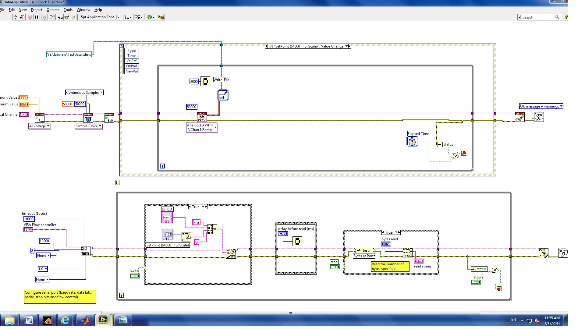
Change the value to trigger record data for 1 s sampling frequency of 50 KHz
Hello
I have a VI with NI9215 and cDAQ-9178 chassis hardware. The function of the VI came out an instruction to RS232 interface and record 1 second of data every time that the set point is changed.
The procedure is
(1) modify the policy to the flow regulator
(2) wait 2 seconds.
(3) record of 4 channels for one second to the sampling frequency of 50 KHz.
At present, the problem is for the first edition of this program, two seconds (rather than) data was saved and corn, the error message 200279.
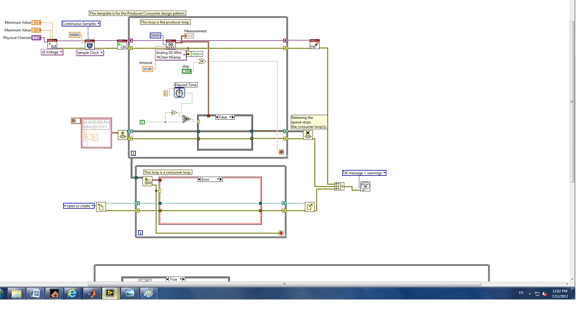
II. I revised for the second edition of the structure of the producer and the consumer who can increase the speed of the buffer.
The question is how to configure the trigger to start the backup of data and limit data save for one second whenever the set point value changes.
(1) which edition is best for my application?
(2) how to trigger the data record?
(3) how to record only a second of data?
I also checked this announcement and the elapsed time seems not to work for this case.
Any help would be greatly appreciated!
Melody
Hello
you have not used properly the nodes property.
1. replace the case structure in the first loop, with DAQmx features, with a structure of the event. Change the event fires for a worth of control of the setpoint change.
Edit: as stated in your first post, use the structure of the event, but put inside the while loop.
2. DO NOT connect error output from the stop command property node. Replace it with a local variable for the stop button.
Try these and let me know.
-
Simultaneous use of different channels the same Module
I use DAQ 9178 chassis to control several module, 9421, 9481, 9207, 9263 and 9213. I wonder if I can call two or more different channels of the same Module at the same time without getting an error of conciliation? For example, DAQ assistant1 use 9213 channel 1 and DAQ assistant2 use 9213 channel 2 respectively. There is a chance that the program could call these two assistants at the same time, which will cause an error? What about the other module, 9421, 9481, 9207 and 9263?
Thank you
Haorong
Hi Haorang-
If you use separate tasks (via separate DAQ Assistant) then I strongly encourage you to ensure in your code that only access comes at a time. If they are running at the same time, then one of the tasks is likely to report a resource reservation error when he tries to set aside resources that are used by the second task.
There is no way to set a timeout for this case, as it would be dismissed by booking / committing the task (see DAQmx help for more information on the States) and not at the time of the reading or writing, so there is no way to wait for the data to be acquired or generated while the resources are released.
-
CO, redeclenchables-based synchronization
I would like to synchronize HAVE, AO and PERFORM tasks finished which are redeclenchables based on a train of pulses CO. I've implemented a CO Pulse Freq task to run off my 9178 chassis ctr3. The front triggered the OD to start, the falling edge triggers HAVE it and GET started. Provided by these tasks finish are short enough, they should be redeclenchables, so whenever my CO sends a pulse they should restart.
Difficult to do this work, get an error that the task of the AI is not redeclenchables (using 9222). Can anyone provide guidance on how to implement such a scheme?
Gracias.
Hello Telleurium,
The error you are getting is expected as the 9222 does not support the redeclenchables tasks, but shipped from the 9178 counters are redeclenchables. I suggest do you the CO Pulse Freq Output a generation over, put in place a trigger for this task, set to retrigger, and use it as the sample clock for GOT it, AO and DO. This will allow you to create a redeclenchables HAVE, AO and the ct3 your 9178 chassis-based. Examples of what I mentioned above in many places. Here are a few to get you started.
https://decibel.NI.com/content/docs/doc-6801
https://decibel.NI.com/content/docs/doc-14581
https://decibel.NI.com/content/docs/doc-4131
Best regards
Izzy O.
Technical sales engineer
National Instruments
-
Wavy jagged singal of 9237 at no load condition
Dear forum users and employees of OR,.
I would be grateful to you if you can solve my problem. My specimen is a simple piece of plastic 1 0.25 inch rectangular cross section with a length of 8 inches. I'm trying to measure the deformation (with the help of use general TML, Japan 1 mm gage length extensometer) in the sample by hanging dead in the sample weights. I am able to strain using the cDAQ 9178 chassis, NI 9237 module with accessory NI 9944 quarter bridge. For a given weight (so the applied load becomes a static), signal (output voltage) must remain constant independent of time. In addition, I also expect that when no load is present on the sample, the acquisition system data above should show constant, but the deformation of almost zero output over time. What is my problem only after offset removal and shunt calibrated correctly with the help of the wizard of LABView DAQ, the above data acquisition system shows a strain of output wavy stair of significant variation between maximum and minimum, even when the sample is at no load condition (the sample is simply placed on the table). In addition, even after loading the sample with a certain amount of dead weight, rather than get a constant signal, I always get a strain of output wavy stair (with more scale position zero load) over time. Please help me get a constant output signal for the data acquisition system above with and without load on the sample.
Thanking you
KSRKM
-
I just discovered that there is no module for 9178 chassis to interface with the drive of the P7000. We can use the serial port on the P7000 to control directly from Labview? What would be the best way to fight against it? P7000 tools to operate the stepper throughout the day.
Thank you for your response. Using portmon, that we could determine the commands used with tools P7000. We have since modbus code embedded in the labview code and are able to control the speed and direction through the serial interface. I hope this fix can help others in the future.
-
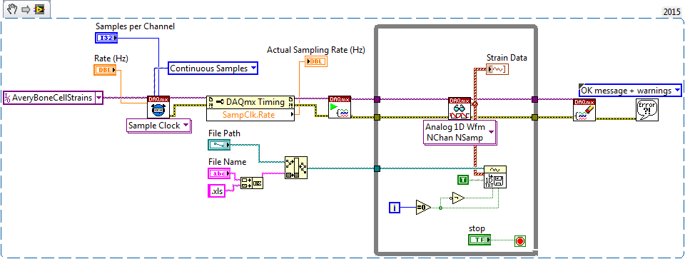
Write entries of similar continuous strain of spreadsheet with headers
I use a cDAQ-9178 chassis with a NI 9235 strain gauge model to collect the analog inputs of the strain of 3 gauges. I currently have a program (see Finite_Strain.vi) that collects the data and writes it into a spreadsheet. I would use continuous instead, sampling so that I can see my curve of deformation-time develop as I run my tests. I wrote a program that does this (see Continuous_Strain.vi) but I'm unable to write data to a spreadsheet. I am currently using the function "Export to spreadsheet File.vi waveforms" as opposed to the function "Write to File.vi worksheet" to write my data in a spreadsheet because it allows me to have data headers and a time column.
My problem is to store all data in my loop. How to build a table of all these data outside the loop and write to keep the worksheet column headings?
Any help on this problem is greatly appreciated. Thank you
Alberto M.
You can do it.
Ben64
-
Measurement of high frequency with the NI 9411
Hello
I would like to measure the frequency of a TTL signal with the 9411 OR in a cDAQ-9178 chassis. 1.6 at 48 kHz frequency range.
With examples of Labview digital frequency meter, it is not picking up on the signal. Any advice?
Anna
Hello!
After talking to an applications engineer of NOR, I realized that the input signal must be less than 5 v. In particular, the bass is between 0 - 0.8V and the top is between 2 - 5V.
Once I have limited input to this range, the module of frequency meter picks up on the signal very well.
Thank you
Anna
Maybe you are looking for
-
Set bookmarks menu dropdown width
After the upgrade of Firefox 4, I find the the drop down bookmarks menu is far too broad. How this width can be adjusted?
-
Qosmio G20-117: bad pixels on the screen and the CD rom does not work
Hello I have a problem with the computer hardware. I got a Qosmio G20-117 and you have a problem with the cdrom and the screen. Got bad pixels on the screen, and cdrom does not work. I live in the United Kingdom, so I tried signing up to them to choo
-
FileVault slows down the operation of the computer somehow
I'm concerned about the use of filevault can slow the operation of my computer. Is this a problem? And Carbon Copy clone work with filevault?
-
BlackBerry Z30 z30 configuration problem
Recently wiped my Z30 and gave my parents to try. We didn't have time, so only partially put in place before their departure for home, 2.5 hours drive. I've defined to the point of needing to connect to wifi or mobile network, jumping id blackberry
-
BlackBerry Tablet OS graphical help cannot sign the application
I use BlackBerry Tablet OS graphics helps convert the apk to bar. It convert the application but cannot sign the application. Here's my output of the operation Batch process Bar signatory began... -------------------Fling.bar-------------------Signat