circular edge
Hi all
I use vision Builder AI 2012 and I have trouble finding the truncated right edge.
The edge that I found isn't always the strongest one. Normally this isn't a problem (I'm looking for the first edge), but sometimes my program detects the edges that I don't want to see. I have played with all the settings, but the results are not always as I expect.
Is it possible to specify the coordinates of the center of the circular edge? That would really solve my problem, but I can't find a setting that makes it.
With sincere friendships.
Tom
You can try to use the step to detect objects that makes it easy on the threshold of the image to find objects (i.e. your circles), and then there's advanced filtering options to throw unwanted objects (only keep objects of circular... This is called the factor of circularity Heyward and the closer to 1, it's the more circular, it is, or filter the objects that are too small too large or touch your region of interest. This step can even return the diameter of the object. This step is used in this example I showed you to count the holes in the oil filter, but you can use it to get the position of the circle.
Hope this helps,
Brad
Tags: NI Hardware
Similar Questions
-
I can't change the discripter KING of the circular edge detection
Hello
I need to find the find of circle using the circular edge detection. Here, I need to change my KING. so I used the property Node display.
But I can't change my KING.
I've attached my VI file
I understand that you want to change your return on investment... have you checked the link I provided in the previous post?
-KING of the ways showing different coordinates, how you give their evolution?
-simply by selecting the property KING will give nothing unless you draw something in the indicator of the image. For example, when you select the tool KING and draw something so the return on investment parameters will be passed to the property node. -
Circular edge IMAQ find 3: result rounded
Hello
Can someone please explain to me the significance of the result "Roundness" of the circular edge IMAQ vi find 3?
I know that the definitions of roundness like MCC, MIC and MZC.
Is one of these related to this result?I get results ranging from 0.1 to over 8 on several images, but it is clear to me how resulting interpreter.
Thank you for your ideas!
Best regards
Roundness or residual represents the least error square of the circle that is adjusted to the set of points. 0 for the perfect circle
http://forums.NI.com/T5/machine-vision/what-exactly-is-the-roundness-figure-generated-by-IMAQ-find/m... -
Error 1074395720 has occurred to IMAQ find circular Edge 3 IMAQ Vision: invalid KING.
Hello
I am writing a program to adapt to a circle of an image (from the avi), but when running the IMAQ find circular edge v3.vi I get the error message:
"Error 1074395720 occurred at IMAQ find circular Edge 3.
Possible reasons
IMAQ Vision: Invalid KING. "
I use the vi KING of construct IMAQ to set the return on investment and I am sure that the KING output is in a format suitable for the discovery of the IMAQ circular edge v3 vi.
I joined my program (Labview 2011)
Any thoughts?
Thank you very much
Rory
Hi Rory,
Welcome to the Forums of NOR.
«IMAQ find circular Edge 3' expects a return on investment for type 'Ring'.» There are a number of functions in labVIEW for the conversion of the type of return on investment as "IMAQ convert the KING to ring. However, as the circular edge VI find JUST does not ring but bounding box and other details as well, there is a strange solution to this problem.
Drop-down "IMAQ convert KING ring" and get the return on investment through. Drop-down and then "Convert ring to the KING" (Yes, really) and pass the output of who to "find the circular edge.
It is circular, strange workaround, but it seems to force the type of return on investment to go to the ring and so works.
Let me know if you have any other questions.
Thank you very much
-
How to cut the lines to get the circular edge?


What I'm asking is how do my lines have this circular edge like the inside of these lines... I'm sure that its some pathfinder tool where you put a circle on the top lines but I can't seem to find the right order to get this look... Any advice? P.S. I'm still tweeking the colors and the others then... AND the largest circle is the one that I was trying to use to cut the lines...
Combine your lines
Draw a black circle on top (black will be your color to make invisible things)
 s
sSelect both
Transparency > make opacity mask, use these settings

Note: there are 2 squares in the transparency palette.
Left square highlighted (as shown above) - edit art
Humble square highlight - modify the mask
-
IMAQ Vision NOR find circular edge
Hello
I had a few a problem with a circular border of LabView Vision search. The problem is when the function found my circle he put a red circle, that's good! but when I move the object to try to follow the point, all the old red circle will not disaper.
After I got everything its quite messy in my interface.
I got a picture of the problem.
I want to know how to clear the circle each iteration.
Thank you
Hi PIOU123,
To clear the overlay use the clear overlay VI IMAQ. An example of this in use VI can be found by going to help > find examples and then navigate to the Modules and Toolkits > Vision > geometric matching > geometric Matching.VI
-
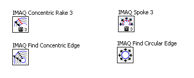
Difference between concentric rake / concentric Edge?
Ladies and gentlemen,
I would just ask you (before I go play myself):
What is the difference between IMAQ concentric rake 3 vs IMAQ find concentric Edge and IMAQ spoke 3 vs IMAQ find a circular edge
(except that the new function supported several types of images)?
I mean these functions:
They seem similar (and assimilated by the features). The 'new' functions are better from the point of view of quality?
Thank you in advance,
Andrey.
Here is my understanding, but I could be wrong:
Talk and just rake will find edges along the paths specified. The edges are the end result.
In the two routines (concentric, circular) edge, the edges are processed to find a circle or a straight line (concentric). These results are returned and a list of the edges. Chances are, if you open them, you will find the features speak and rake in their breast.
All these functions have been around for a while.
Bruce
-
In the assistatant vision, we can give it away to find circular edge. but in the labview I do not know how to give. How to give value to gap in the circular edges detection and how do I get the circular edge points?
Value of gap for circular edge is given as angles (degrees). In vision assistant parameter is empty and the equivalent in labview is circle Fit Options > step size.
N ' be sure to read the help of vi in case of doubt.
-
Error 1074396154 allocated to off-delay.
I use a camera GigE to capture an image and then check for a hole using IMAQ find a circular edge. Whenever the device receives a trigger of the while loop processes and the results are displayed. If the release is delayed for more than 5 seconds, I get error 1074396154 (IMAQ Spoke - not big enough Image for the operation).
The loop must wait for the next picture before the treatment, so I do not understand why the error is generated. Any suggestion would be appreciated.
Kind regards
Doug
Hi Doug,.
Have you tried to increase your timeout on your camera? The default value is 5 seconds and you see this behavior in 5 seconds right that might be causing the problem. Increases the open timeout measures and Automation Explorer, select your camera, select the attributes of the Acquisition down and increase the time-out value to 10000 ms.
Acquisition from GigE Vision cameras with Vision Acquisition software - part II (Figure 4)
http://www.NI.com/white-paper/5750/enTim O
-
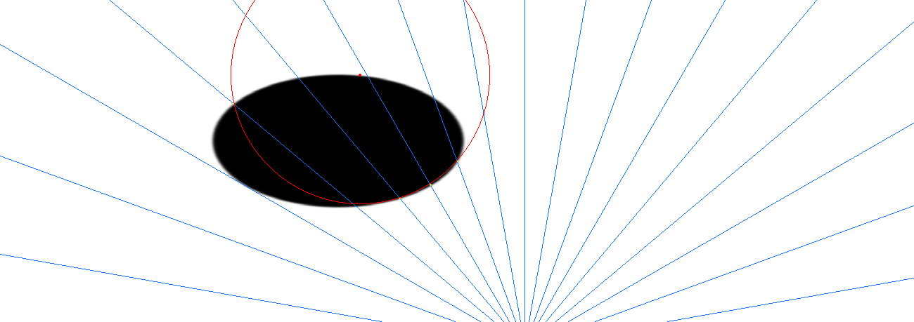
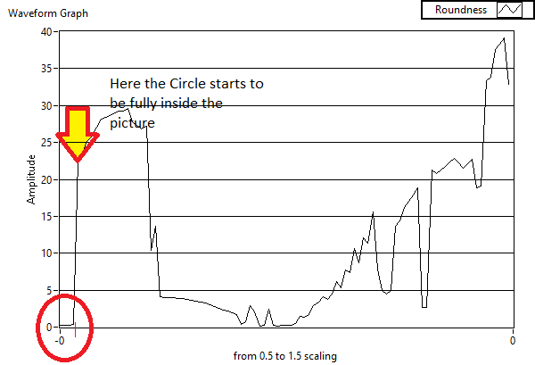
Roundness / residual - weird behavior
Hello
I did experiments to understand the "roundness" in circular edge find - which seems to be the residue of the 'worthy circle '. I noticed a strange behavior, and to understand it, I wrote a program that will scale the width of a circle 'perfect' 0.5-1.5.
I expect a few glitches, jumps... because of the discretization, rounded... etc, but then I came across something that makes no sense: when I detect a circle which is partially outside the image, the roundness is suddenly very low value.
To visulalize, I want to talk about such an image:
The roundness behaves like this:
I don't know if it's just my vi (I enclose the example image and the experimental vi), but can anyone explain this behaviour and give me an idea how to avoid it?
Thank you
BirgitYour last ellipse is locate only three points. You can only fit a circle to three points, and it's a perfect fit. Thus the residue would be very low. It has nothing to do with the circle being outside the bounds of the image.
Your second test to find a large number of points, and the adjustment is not very good at all points. The residue is so great.
Your search for edge must find a large number of points to be able to adapt the circle with precision. You would need a much smaller angle not in your search for edge, especially if you are trying to find objects from the outside.
Bruce
-
VBAI: Problem of coordinate reference system
In a stage of my VB AI application, I'm set a mark at the center of a circular object correctly. In the next step, I do a 'find circular edge', including the "Reposition region of interest" value to a coordinate system.
However, when the object is moving, and the coordinate system with it, find a circular RIM does not follow this coordinate system, but rather remains fixed in space.
What should I do to have find a circular rim move with the coordinate system?
Make sure that when you set up the step of the coordinate system, you put up-to-date in the X direction and Y. By default it puts just updated in the X direction, and even if the overlay appears updated in both directions, this can be misleading. If this isn't the problem, you can include a simple inspection with some images to illustrate how you got in this State.
Thank you
Brad
-
To access the 'IVA Store results'
Hello
I can't seem to find a way to access stored information "IVA store circular edge results", see below to store the information of "IMAQ find circular Edge3.
Advice, please?
The purpose of this VI is to store the results of the DV that returns the points and angles in a results Manager (database of the results of each step), so that they are easily accessible through the following steps as a system of coordinates or caliper. You should not need to use this VI to access the data produced by the circular edge find. Just use the outputs of the circular edge find 3 VI IMAQ.
But that's a good point. In this case, given that your script uses or another step after the circular to find edge, we should not have fallen this VI in order to simplify the code.
We chose to use a producer/accessor model instead of data flow, because all the screws that points and exit angle are heterogeneous. Some indicators are a cluster of points, some are paintings or points, some are table of cluster of points and other things etc. Using data flow, it would take to generate specific code for each producer.
Hope that makes sense.
Christophe
-
How to insert circle text in Indesign?
Hello
Is it possible to write text such as a circular periphery? IE circle-text?
I have a logo that has the shape of a circle, it is not created using Indesign, so I don't know what to do.
I don't want to change the image, I want to only replace the text that goes around the periphery of the circle/circular of this logo.
So I need to remove this text and replace it with another using Indesign - is it possible to do? How?
I have to use some sort of gum in Indesign and delete the text that goes around the circular edge of the circle logo and then create a new circle-text frame? How do I do that?
Would be grateful to finally address this issue.
Like, rachida
You can not in InDesign. You will need to change the logo in the original application or re-create in ID.
-
Disassemble a vector object (formerly type)
Hello
Hope you are well.
There are a cast of dingbats. I want to manipulate one of them by deleting or removing the vacuum/stroked circle around the symbol. For starters, I create outlines on the tile. However, when I use the pen tool to try to remove the anchor points on the race, the result ends up by being off the race, but it also fulfills the race with the color of the stroke (when I don't want one at all and replace the symbol by white.
I've attached an example of forward and after to see what I mean.
How can I just get rid of the original circle around the symbol?
Thank you!

The current font formats actually contain no features. What you think, it's a single circular path with a vascular accident brain is actually two subpaths of a composite path. You can just altClick the outer edge of the circle with the white pointer and delete. This will give you that what describe you as 'after '. Then altClick the other circular edge and remove it. Which leaves you with what you want.
The white needle is able to select the subpaths of paths composed without having first to release the compound. By pressing the Alt modifier causes the pointer to select a full path instead of one of its segments of white.
JET
-
Follow a circular object with the corners Mocha AE?
Hello
I don't know how to phrase my question, but I'm betting it has already been answered, and I do not know.
I found the video after the video on how to replace a "screen" in After Effects with just a few clicks and a fast corner of Mocha AE pin data. However, I have an object that has a circular face (a kiwi being cut in two). The Interior of the kiwi roll to face the camera (the seeds are excellent for tracking). I am able to follow the circular face and be able to get a very precise "plane" of the face of kiwi. The face has an edge that ran a bit, so I just set this task with a perfect face 'ring '. However, I don't know how to translate these data from Mocha AE (corners?) on a non-rectangle (circular) object in After Effects.
A single method, I tried was to photoshop the face of the kiwi's own, then imported into AE, then stretched from the image to fit the model and finally just stuck right corner pin data Mocha AE precomp own kiwi. It was working fine, except that because I don't know where the "corners" are on the kiwi, it does not fill the face of the kiwi perfectly (it corresponds to traffic and is not adrift, but it is not placed exactly right-close, but not perfect).
So, I do not know how to ask the question, but you can refer me to some links that may help me understand this? I'm much more competent after effects camera Tracker, but it does not give me a clean path. I have the open beta for Cameratracker of the foundry, but it is terribly slow and seems buggy (and I'm not familiar with how it works). But again, I am able to follow the plan perfectly in Mocha AE, I do not know how to set the placement in AE.
Thank you!
-Stephen
Follow the surface in Mocha, apply tracking to the corner pin data, make a mask or a track matte and you're done. Take a look at this:
Imagine that the TV is the kiwi


Maybe you are looking for
-
Where the hell the web address bar went, and why do I get it back?
I want the Web address Bar back without the multitude of OTHER toolbars so that I can actually go to an adresse_web rather than search the Web.
-
Connection problem of my new (5 s) iphone to itunes on mac - error pops up on the computer saying a newer version of itunes required, however my itunes is already updated to the latest version (11.4)
-
Get the execution time of a VI
Hello I want to calculate the time that my VI is running. Suppose that if my VI worked for about 10 min while I want to make a message appear. But how to do this time. I tried using the "time VI', but its does not give me the desired output. All of t
-
Can I open a preliminary draft in the new version of muse?
It's maybe a stupid question, but I'm new to this preliminary stuff.My question is: if I create a new project in a preliminary version, I'll be able to open it when the new version of muse comes out?
-
Need help with this find/replace Script.
Hi I got this script from Loic.Aigon. And I got it works for find/replace simple changes however I Cannon operate for several changes. function cb5CallBack(target) { var findProps, changeProps; findProps = {findWhat:"Dist