component in Multisim
Hi guys,.
I just started to learn in Multisim. I tried to add a 4011 and 4017 CMOS Gate in my circuit, but I do not know how to connect VDD and GND to the ICs. Because there is only input and output pins. I also wonder if I can expand the 4017 itself on my diagram. I know how to increase the zoom of the entired schema. Please advise, thank you.
Harrison
Tags: NI Software
Similar Questions
-
creation of component custom Multisim version 12
Hi guys,.
So I am a student with a project I have to simulate on multisim. It is not part of the project, but the project has over 100 components inside so I started to wonder if I could make my own components with the circuits inside of them.
So ive trying to do a custom of my smaller circuit component to test if it works and race dramas.
The circuit is a code of grey 8-bit binary code converter.
If I had done the converter and put connections HB/SC on the inputs and outputs.
Then registered as a netlist cir file.
I then opened in Notepad, added
. SUBCKT G2B_8BIT G0 G1 G2 G3 G4 G5 G6 G7 B7 B6 B5 B4 B3 B2 B1 B0
up, so my component is G2B_8BIT, and these are the names of the 16 pins
I then added. ENDS at the end
I haven't added any mapping of pine because it is only a simulation need not print
If I replace the circuit with the component that I did, it does not work and there are no errors or warnings to see ive done something wrong.
Ive my files attached
There is the original circuit
The circuit, that I used to create the EIF file.
My cir file.
and the new circuit with the added component
Your help would be much appreciated, I am interested to know how it works
Sorry wrong answer to and joining the new circuit with the addition of component, like I can join only three files
Hi Cruizerdog,
You can build a model SPICE of a circuit only when the components you used have a SPICE syntax, Multisim's database digital parts are not SPICES, it is based since XSPICE. The model that you have tried to create won't work.
-
Toolbar of component on Multisim 11.02
Hello
I recently purchased and activated a version 11.0.2 Multisim student I am creating a circuit and there is no toolbar of component present among others. All the relevent boxes seem to be verified through display-toolbars, toolbar should be present but is not.
Hi Robert,.
Thanks for your reply.
If possible, I would recommend now uninstall multisim, it could be a corruption of multisim himself. Also after uninstalling, please remove the folder C:\Program NIUninstaller Instruments\Circuit Design Suite 11.0. Then restart the PC and re - install.
Kind regards
-
-
by using labview co-simulation, how to control the PWM market factor in multisim
I am new to the use of Multisim with LabVIEW using co-simulation. I would like to ask if there is a PWM component in Multisim, which can have its cycle have to be controlled using LabVIEW? I have an algorithm in LabVIEW that returns the duty cycle values between 0 and 1, representing the percentage of duty cycle.
How can I control the PWM market factor in Multisim using LabVIEW co-simulation?
Thank you very much
SPECTRUM
Hi spectrum,
In Multisim, find items based on functionality, there are some PWM models in the database. Take a look at this knowledge base if you don't know how to search for parts:
http://digital.NI.com/public.nsf/allkb/7309A5CABC677296862577ED006EC99E
Also, take a look at this knowledge base:
http://digital.NI.com/public.nsf/allkb/EF391C48CF71AE4F862571B900644F84
This article shows you how you can get Mutlisim and LabVIEW to co-simiualte:
http://www.NI.com/white-paper/13663/en
I hope this helps
-
Could not find LM238 regulator of tension in Multisim
I am new to Multisim. I can't find a LM238 voltage regulator in the library under sources power supply voltage regulators. In fact, I did a general search and could not find anywhere. What is usually done in a case like this? My intuition tells me that I wouldn't need to redraw my circuit just because I can't find a component in Multisim.
Thanks in advance.
Hello
We don't have a model for the LM238, but we have a model for the LM138. According to this data sheet, the LM138, the LM238 and the LM338 are identical with the exception of the beaches of operating temperatures. You can place a component LM138 to the master database and use it for the simulationand implementation.
Hope that helps.
-
Apex PA50 SPICE model used in Multisim
Below, I pasted the code of the Apex SPICE for their PA50 power amp. I tried to use the Wizard component in Multisim, but when I run the simulation I get the following errors:
1st a popup) an error was found in the Netlist, would you like to continue nevertheless?
2nd if I proceed)-netlist SPICE checking to Apex_PA50 - Saturday, July 20, 2013, 12:54:12 -
Error of SPICE Netlist in schematic RefDes "u1", item 'xu1': unexpected '6' found subckt - too many nodes or missing name value parameter instance online.
Error of SPICE Netlist in schematic RefDes "u1", "" element: due to errors, the instance subckt 'xu1' has been omitted from the simulation
= SPICE Netlist verification completed, 2 error (s), 0 warning (s) =.You SPICE gurus out there knows how I can get these kinds of patterns Apex in multisim? They are really big amplifiers.
Thank you
Robert Harker
***********
* REVISION 2 MARCH 18, 2002
* REDUCTION OF INTERACTION OF THE SLEW RATE WITH CHANGE IN DIET.
* START OPAMP MACROECONOMIC PA50
* STITCHING ORDER IN - IN + OUT + VB - VB + VS - VS
. SUBCKT 1 2 3 4 5 36 37 PA50
10 1 8 JI1 J1
11 2 9 JI2 J2
12-8 1.34E + 03 R3
12 9 1.34E + 03 R4
I2 5 12 4.50E - 04
5 12 5.00E C1 - 13
5 12 + 06 5.45E R5
10 4 1.59E + 03 R1
4 1.59E + 03 11 R2
10 11 1.67E C2 - 11
4 5 2.64E I1 - 02
G1 6 15 11 10 6.28E - 04
G2 6 15 12 15 2.81E - 08
6-15 1.00E + 05 R6
6 15 DD D1
15 6 DD D2
6 7 7.50E C3 - 12
15 7 15 6 + 01 1.00E G3
7 15 1E3 R7
16 7 DD D3
18 16 + 00 5.50E V1
7 17 DD D4
17 19 5.50E + 00 V2
RE1 15 0 0.001
38 0 4 0 1 E2
39 0 5 0 1 E3
R8 7 20 50
20 15 5.80E C4 - 11
37 20 21 QOP T3
36 20 22 QO'QON T4
36 21 29 QO'QON Q5
37 22 29 QOP Q6
41 36 38 36 0.69 E4
42 37 39 37 0.69 E5
18 0 41 0 1 E6
19 0 42 0 1 E7
RY1 38 0 10E6
RY2 39 0 10E6
RY3 41 0 10E6
RY4 42 0 10E6
I3 36 21 5.36E - 03
I4 22 37 5.36E - 03
I5 37 36 1.0E - 02
29 3 8 R15, 5TH-02
29 36 DC1 DO
37 29 DC2 IS
. MODEL D (CJO = 10PF IS = 1.26E - 12 RS = 2.38E - 03)
. MODEL D DD (CJO = 0.1PF IS = 1E-17)
. MODEL DL D (CJO = 3PF IS = 1E-13)
. MODEL JI1 NJF (BETA = 4.00E - 03 EAST = VTO 3RD-16 = - 1).
. MODEL JI2 NJF (BETA = 4.00E - 03 EAST = VTO 3RD-16 =-1,0050)
. MODEL QOP PNP (BF = 2.35E + 04 IS = 1E-14)
. MODEL QO'QON NPN (BF = 2.35E + 04 IS = 1E-14)
. MODEL RLQ NPN (BF = 100 IS = 1E-14)
. MODEL SPCA PNP (BF = 100 IS = 1E-14)
* END OF OPAMP MACROECONOMIC
. ENDS
************
I haven't studied your ad but clearly the xU1 call isn't in a SPICE compatible format. The definition of subcircuit PA50 has 7 knots. Your call xU1 has 12! Nodes U1_OPEN_11 and U1_OPEN_12 exist anywhere else in the document.
Lynn
-
Hello
I would like to convert spindle IBIS models to patterns of behavior SPICE I can import in multisim. I then combine these models of PIN with others built in components to make a simulation of end to end. I tried the free converter of Intusoft and get several errors when I import the SPICE circuit in a new component. My question to the group is, does anyone know of an IBIS in the converter of SPICE (free of preference, but ready to buy something if necessary) that generates a code that can be imported directly into a component of multisim with no editing? I guess that I would accept a small change, but I have several pins to bring and don't want to risk screwing the underlying model
-Steve
Hi Steve,.
There is no particular way to IBIS spice that is recommended for work in Multisim. I think that if there is no chance of finding that the Spice model would be the best option. There are some other forums with more information on IBIS to spice. It seems that thay use the same tool that you have.
Kind regards
-
Power Supply missing components
Hello
I am a first year electronic engineering student and I would like for obvious reasons, like to get to know and use Multisim.
So I decided to build a power supply on it to test with different loads and gadgets attached to it. Initially, it seemed easy enough until the
I realized that there are some items that I can't find on the database and will have to do it myself. Im not that PRO yet and I only have 6 days left on the trial.
Could someone help me please? Just point the equivalent components on the basis of data of OR
Here's the food I want to build and simulate it on Multsim.
http://www.rason.org/projects/powsupply/powsupply.htm
I've had trouble finding a voltage regulator and some of the Transistors aswell.
Thanks and greetings
Basket
Hello
If you cannot find a component in Multisim, you can always create it using the Component Wizard (Tools menu), this is a basic tutorial:
To create a component simulatable, it need a SPICE model. SPICE models are therefore created by manufacturers, visit the manufacturer's Web site to see if they have the model you need, you can also use a search engine.
For your reference, I have attached a file Multisim with the LM723. You can save it in youruser database, just right-click on the component and select Save to DB component.
I hope this helps, welcome to Multism!
Kind regards
-
Modeling and Simulation occur error
I have established a model APEX PA78, but the simulation reports any error, please help me!
View report worksheet is followed:
-Audit netlist SPICE to PA78 - 2010-01-28 20:12-
Error of SPICE Netlist in schematic RefDes 'u2', item 'xu2': unexpected '15' found subckt - too many nodes or missing name value parameter instance online.Error of SPICE Netlist in schematic RefDes 'u2', '
' element: due to errors, the instance subckt "xu2" has been omitted from the simulation Error of SPICE Netlist in schematic RefDes "u1", item 'xu1': unexpected '1' found subckt - too many nodes or missing name value parameter instance online.
Error of SPICE Netlist in schematic RefDes "u1", "
" element: due to errors, the instance subckt 'xu1' has been omitted from the simulation = SPICE Netlist verification completed, 4 error (s), 0 warning (s) =.
---------------------------------------------------------------------------------------------------
The accessory includes three files, they are:
PA78. TXT is the BERKELEY SPICE on PA78 model of
http://Apex.Cirrus.com/en/products/Apex/design_software.html
PA78U_B.PDF of page on PA78 of
http://Apex.Cirrus.com/en/products/Pro/detail/P1163.html
PA78. MS10 is a configuration of bridge-connected, but PA78 itself do not work a simulation.
Hello
I'll expand a bit what Angela said on the. ENDS and then try to clear up the pins.
The SPICE model that you use for the PA78 includes several subcircuits and models. Best practices for creating a component in Multisim are having one. SUBCKT or. MODEL for each component. The point of this is to ensure that the additional models or models contained so that they do not interfere with each other in the final netlist. The best way to solve this problem is to move the. ENDS during the main subcircuit until the end of the complete draft - so, instead of simply add the. ENDS at the end, you must also remove the first. END of line in the file. For this circuit, you probably don't need to do it, however in general, it's a good idea to do by making a component like this.
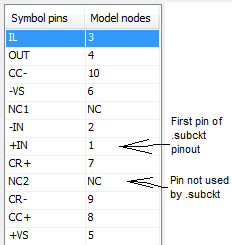
With respect to the pins, step 6 of the component wizard asking you order the pins will be used in the model. The (original) model that you have only 10 knots, so it isn't a problem if you have only 10 pins there. If you have 12 pins on your symbol, and only 10 model nodes, then you score just two unused pins as "NC"(vous pouvez également ajouter deux broches"fausses"pour le.) ". SUBCKT which is what you did, but you have not).
For the rest of the pins, see the. SUBCKT line and comments just ahead of him:
* PINOUT ORDER +IN -IN IL OUT +VS -VS CR+ CC+ CR- CC-* PINOUT ORDER 7 6 1 2 12 4 8 11 10 3.SUBCKT PA78 7 6 1 2 12 4 8 11 10 3
Comments indicating the order of broaching tell you the order in which the terminals must be indicated when you use the PA78. SUBCKT. As you can see on the. Line SUBCKT and comments, even if IT is pin 1 on the component, it should actually be listed third when you use the. SUBCKT. It's asking you to step 6 in the component wizard. Step 6 allows you to specify the order in which to use the pins to Multisim. The comment you indicates that + is the model node 1, - IN is model node 2, IT is the model node 3, etc., and then you say Multisim by setting the number of nodes of model
Hope that helps!
-
Multi resistance vs ultiboard imprint imprint
Hello
I placed a chip-0603 resistance on mulstisim, and when I transferred the ultiboard design, he was placed as a RESC1608X63.
After nodding with routing, I decided that I needed a wider space between the resistance and that an imprint of RESC1608X84 adapts well.
After changing the footprint in ultiboard, I commented back to multisim - but there multisim can't find the RESC... X 84 imprint.
How can I create a link between the different types of RESC1608X * to the footprint of chip-0603 CPI multisim?
Thank you
ADI Z.
Hello
The two programs have the same database, but there may be cases where a fingerprint in Ultiboard who is not assigned to any component in Multisim is not visible to Multisim. The opposite is as I said to save the component in a different database than the master.
I hope this helps.
-
Component USB 6008 in Multisim
Hello
I conceive my system in Multisim 12 and I wanted to include OR components of the database.
I need a component for the NI USB-6008 case and the other for the NOR cDAQ-9174 with two NI9217.
My question is: these elements already exist (in the database, on the Web site of OR or a third party) or what I have to design?
Thank you
csiquet,
Here is an example of a database of these parts NOR (symbol only):
To merge into your DB, to do this: tools-> database-> merge database
There are 'rated' components blow up / stop working if too much voltage/current passes through them.
Master DB-> base-> Rated_Virtual
Kind regards
Pat
-
Coaxial connector in Multisim component
Hello
Im looking for a component of coaxial connector in the Multisim database as well as the site of components listed here. But I couldn't find one. Can someone get me a clue on how to find it. Thank you.
hers,
There are several symbols of 2-pin connector that you could use and attach them to the available Ultiboard fingerprints or footprints BNC customized based on what it takes, however, here is a diagram with a BNC connector for example with a standard configuration of symbol of the BNC.
Do not hesitate to register for databases, and customize with no specific information (that was created for a 50 ohm coax).
Kind regards
Patrick Noonan
Business Development Manager
National Instruments - Electronics Workbench Group
50 street market 1A
S. Portland, ME 04106
E-mail: [email protected]
Phone: (207) 892-9130
Telec. (207) 892-9508 -
HP and/or Techtronix Multisim and GRAPHER
Is there anyway to have the results of the Tecktronix and the HP o-scopes in Multisim appear in the Grapher? Not sure why they don't, but they do not.
Hello
Impossible to Multisim to connect directly with third-party tools and import signals from the scopes in Multisim. If you are able to get information on the scope and create a file .csv with this information, you can import this file in Multisim.
I got this from another forum.
"The Piecewise linear (PWL) source accepts data as the voltage or current time. You can find this part by selecting site > component, go to the group 'Sources' then select 'Sources of voltage Signal '. Place this part on the working area, double-click it and there should be an option to open a .txt file.
-
Import the SPICE model for transistor BJT BFP720F in Multisim
Hello
I'm trying to get the SPICE model for the BFP720F transistor provided by Infineon to work in Multisim.
I have attached the template as provided by the manufacturer.
If I import it as-is, I get error messages "invalid node identifier '<4>'" (I have translated that German, it might not be exactly this message in the English version).
So I tried to replace all the "<4>" with "4", which seems to help, but now the error is "adjusted temperature setting"VJC (PC)"negative" and "incorrect use of the parameters of the model. Now I don't really know what to do with it.
Is the template provided in the wrong format? I somehow can it in the right so I am able to use it?
Because I need for my project semester in College, any help would be much appreciated.
Thanks in advance!
Hi NikoNR,
When writing a detailed description of what I did exactly with the Wizard component, the component again to create in Multisim from scratch, I found that there are different SPICE models provided in the package for use with AWR MWO. They have a different file extension, but are normal text SPICE inside files.
It turns out that they actually work with Multisim. The difference is small, there is only one temperature (TNOM) setting that is absent in these models, distinct from the "general" I first tried to use. It seems that Multisim had a problem with this setting, leading to the error I encountered.
Anyway, the problem is solved now. Thanks for your help

Good day
(The now much happier) EE-student
----
Edit: I have attached the SPICE model, that I ended up using, in case someone at - he never met a similar problem. The only change I did this, is to replace '<4>' with '4' in the part of the diode (single occurrence here). I had to zip to download with his original extention (.mdl).
Maybe you are looking for
-
How can I sync iMessages with Samsung Galaxy phone?
How can I sync iMessages with Samsung Galaxy phone?
-
Active screen/window becomes inactive on its own.
I've had this problem for quite a while now; whenever I am active in a window to say to, for example Internet Explorer or type in MS Word, it automatically becomes inactivated. Happens at various intervals, and it is just annoying, because I can be t
-
How can I fix an image that is missing the border on one side?
I will use this image as an example.As you can see, she has a border on 3 sides, but lacks the border on one side. What can I do to add the border to the side where it is absent? I don't want to hide a part of the image itself. What do you recommend
-
I need two part number in 3020 OptiPlex Mini Tower
The switch and the speaker can help me? @SpeedStep
-
I can't open my premiere Pro CS6 downloaded version
Hello!I have tried to install Premiere Pro CS 6 on my laptop, (Windows 8 Aspire switch 10,) but it does not work. I can't find CS6 and I tried to found in the computer several times now. How can I insall / find? Works perfect programs.Thanks in advan