componet 485 communication
Hello
is there an element of 485 communication, both single direction and communication in two ways. or where I can find this model
problem of the anther, in multisim library, having a component of communication infrad Red?
Thank you!
We have an existing discussion on RS - 485, but the SPICE model evolves from an IBIS model. What this means is that, generally, IBIS is good to show you the transition to digital and data loading, but not likely you will get a functional model of SPICES you want. Here are the previous thread.
http://forums.NI.com/NI/board/message?board.ID=370&thread.id=844
RS485 transceivers are relatively simple, but they convert ended to differential signals and speed and the specifications that could create a functional model of charging base. As a starting point, you NOTICE specific in mind, there are several Maxim (full/half duplex) which could be appropriate choices?
Same question with the infrared communication component - please let us know a reference number of a typical device would seek you to.
Kind regards
Patrick Noonan
Business Development Manager
National Instruments - Electronics Workbench Group
50 street market 1A
S. Portland, ME 04106
E-mail: [email protected]
Phone: (207) 892-9130
Telec. (512) 683-7754
Tags: NI Software
Similar Questions
-
On the NI PCIe-8433 terminating resistor?
Hello, can anyone help me find the terminating resistor on the NI PCIe-8433-2 ports for PCI Express card isolated Serial Interface? We do RS-485 communications and there should be a 120 Ohm resistor on the two ends of the link. Someone know if the terminating resistor is installed by default or should he add?
Thank you
Joe
Hi joe5213,
Termination resistors are not included in the serial products OR because they are not always necessary. Here is a document showing how suggest us their installation. You can also use the Connector DB-9 RS-485 networks endpoint (P/N 182844 - 01) If you prefer.
-
Disable a test socket when executing (Batch Mode)
We had a model of batch processing with synchronization of batch. I wonder if it is possible to completely disable one or more of the test socket when running. I know that the opening screen allows you to choose which sockets are active, but in case something goes astray as the RS-485 communication is inadmissible, I would like to disable one or more at any time during the test. Thank you in advance for all the ideas come you up with.
Concerning
Scott
Environment: TestStand 2010
Greetings SunRS and dug9000,
Thank you for both of your responses. I appreciate the information that you gave and I'll create another post if I need more information.
Kind regards
Scott
-
Hi, I need to communicate with an encoder Kübler RS485 using commands Esc (
00P) for the position). I have been using VISA VI with other instruments for a while with no problems. I have computers with windows Vista and XP and it seems that these commands need in real time which is not compatible Win XP/Vista. Any help will be appreciated. Thank you to Dear sisco79901,
Encoder of what model you are using? It is the closest, I could find:
http://www.clrwtr.com/PDF/Kubler/Kubler-9081-absolute-encoders.PDF
And for this and other models that I have watched, configure you the hardware configuration by setting some lines either high or low before feeding the encoder.
Can you provide a link to the technical data sheet or manual for your specific encoder? I have also found not any reference to these commands Esc in any of the Kübler writings that I have watched so far.
If you send commands to control lines specific in respect to this low voltage or high, you can use any device which will output the appropriate voltage (MIO DAQ card for example) and DAQmx driver in LabVIEW.
If you need to send these commands via RS - 485, then you can always use the driver NI-VISA, because it supports serial RS-485 communication.
How can I enter the escape (ESC) character in LabVIEW 6.1?
http://digital.NI.com/public.nsf/allkb/86256A47004E16D186256A3E0051653A?OpenDocument
Inserting Non-displayable characters in strings
http://zone.NI.com/reference/en-XX/help/371361B-01/lvhowto/inserting_non_displayable/
Send the escape character
http://forums.NI.com/NI/board/message?board.ID=170&message.ID=255093&requireLogin=false
Best regards
~ Nate
-
view laboratory with a CIF 50 Hilscher Profibus interface.
Hello
I need to view laboratory with a CIF 50 Hilscher Profibus interface.
I read some documents provided by Hilscher, he spoke of Sys - Con, OPC servers etc etc.
Through this profibus, I need to check a box of valves through RS-485 communication.
The first task is basic read/write. By lab View I have to read the number of bits through 50 CIF bus in turn to the Valve box.
Can someone tell me where I should start? -
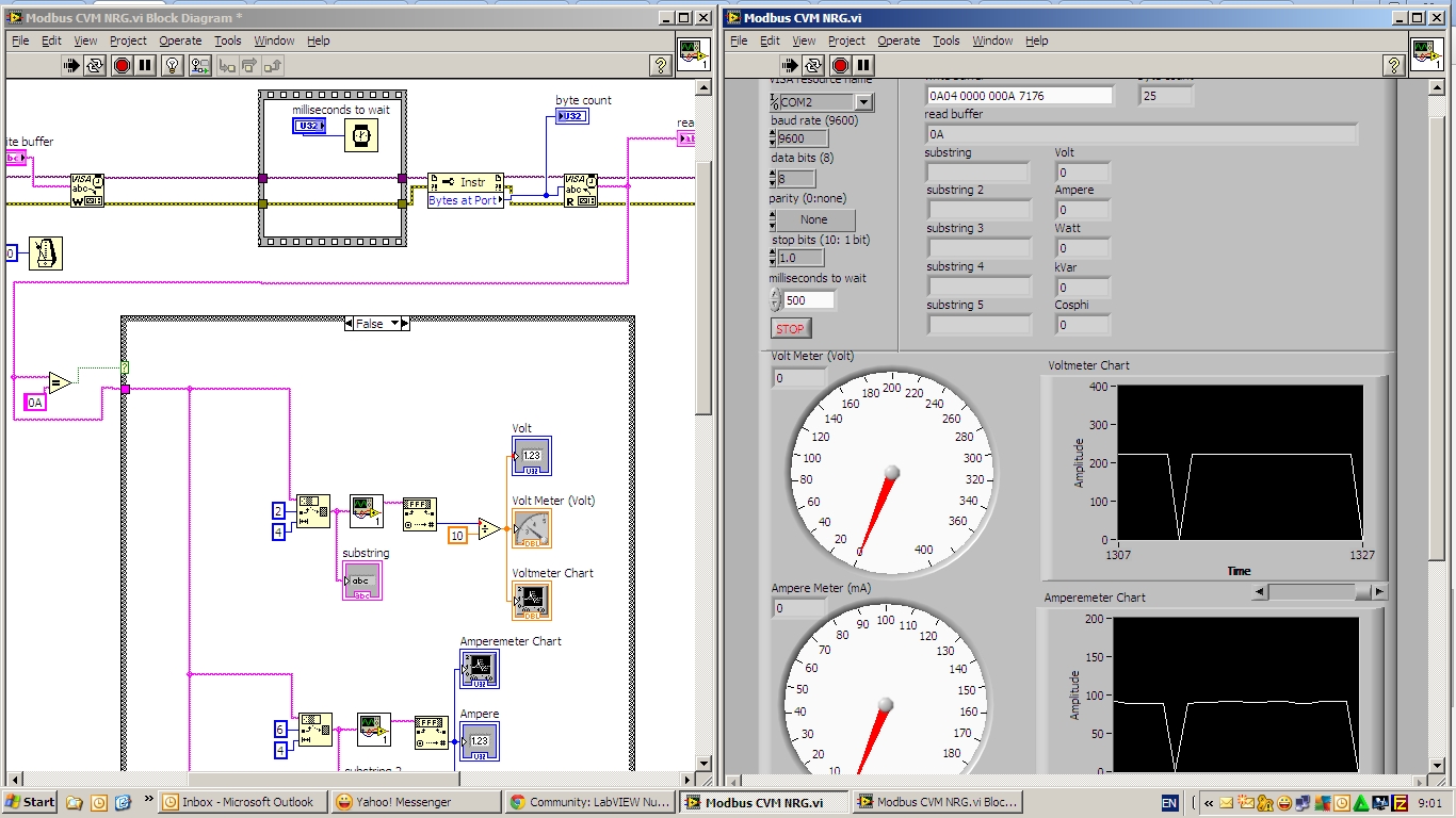
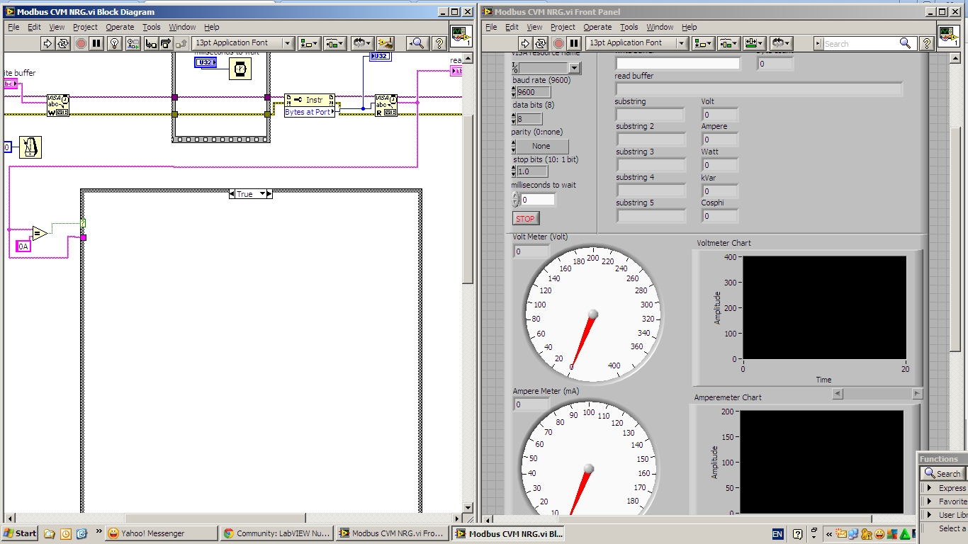
Communication RS-485 digital custom
Hi all
I have problem of RS-485 serial communication using NI VISA.
My problem is sometimes the data that must be read from the power Analyzer suddenly loss, if I skip this problem? so if data loss my program not the analysis of data from the power Analyzer, and then sometimes brutally data are raw (I think that error on read VISA) I can ignore it at?
I did many programs and still not working properly
Sorry for my bad English.
This is my video watch it please
https://www.dropbox.com/s/st6qs1cbtr72m0m/Bandicam%202014-05-05%2015-06-09-546.avi
Thank you ~.
-
with boredom Watlow PM 485 modbus communication
I have a PM Watlow I see now at MAX and using EZ area code can get info manufacture of. I also uses the Modbus in the add-on on Saphire series tool to try to write or read anything from him (for the first time) and I always get an error of 'time' out of the slave. I tried to make a simple reading of VISA I found on some positions, and I get the same timeout error. It seems that if I try something Labview I get this error. I even tried writing Hex to the thing with the same results. Can anyone throw me a BONE?
There are a couple of free libraries.
-
Connection RS-485 for the climate control ESPEC Chamber
Hi all
I'm having some difficulties of implementation and the RS485 connection with ESPEC climate control room.
It is a room of climate ARL-0680. The climate Chamber has two connectors male DB9 on the outside, apparently used to connect several rooms to RS - 485.
The pinout of the connector RS485 DB9 real is:
1: Data Transmission SD + (A) connected
2: SD-Transmission data (B) connected
3: data reception RD + (A) connected
4: data RD-reception (B) connected
5: GND mass connected
6: GND mass connected
7: NC (not connected) not connected
8: NC (not connected) not connected
9: NC (not connected) not connected
I bought a cable interface OR USB-485. This cable also has a DB9 Male interface but the pinout is different.
1: GND
2: CTS + (HSI)
3: RTS + (HSO)
4: RXD +.
5: RXD -.
6: CTS-(HSI) -
7: RTS-(SSA) -
8: TXD +.
9: TXD -.
-The list of the pins do not match and I see names of different signals on both interfaces.
Am I right assuming that I should only make the following connections:
USB485 NOR to the climate Chamber ESPEC
1 5, 6
2 not connected
3 not connected
4 3
5 4
6 not connected
7 not connected
8 1
9 2
Is there some special things I need to do in SW for this configuration to work? I'm using LabVIEW as my programming language to try to control the climate Chamber.
I especially do not know how I need to put in place the transmitter/receiver mode for all either works...
ESPEC documentation, I found that the communication system used is 'synchronized Modulation (four sons, half duplex).
Thank you 1 million for all of your helpful comments!
K.
You connected Rx to Rx and Tx of Tx.
You must connect Tx Rx and Tx Rx. In this way, you create a four-wire interface. Also, you must set your Board of Directors (MAXIMUM) 4-wire.
To make it perfect, you should also connect a 120 Ohm resistor at each end of the balanced line. So in total 4 resistors.
If you want I can draw you a picture to replace these (1 k) words.
Kees
-
Faced with setting up a connection RS-485 for a for OR cDAQ mass flow controller
I'm an absolute beginner from the ground up tries to connect the port RS-485 to a mass flow controller (MFC) Instruments Sierra for the NOR cDAQ.
The planned route of the person in front of me set up for the connection is:
(1) cable MFC COM1 to Interface Ethernet 4 ports for RS485/RS422 (DB-9 to DB - 9)
(2) Ethernet 4-port Ethernet Interface RS485/RS422 OR cDAQ cable
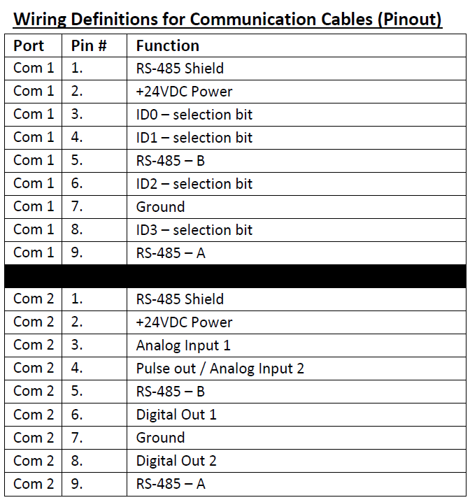
I'm fighting to understand exactly how the pins should be doubled for the 1st part of the interface. For MFC COM1 pinout is given below:
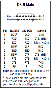
The pinout for DB-9 male, shown in the quick reference Guide series of NI is illustrated below:
I do not know what pins on the side MFC should connect to which pins on the side of the ENET-485. The manifesto is ground (PIN 7 to pin 1). In addition, I'm stumped. Try to read references online has just served to confuse me even more at this point...
Any help would be appreciated!
Follow-up: I bought a B and B Electronics ULinx USB converter to RS - 485 9 pin as well as a cable of Sierra Instruments. I was able to confirm communications between the cDAQ and the MFC using own Sierra HMI as well as through NOR-MAX provided.
-
Read power meter in LabVIEW via RS-232/RS-485
Hello!
I have a power meter, an advanced WM14 DIN power Analyzer. I want to display different values, Kwh, WILL, etc. Kvar, the meter in the graphs in labview. I have just a basic knowledge of Modbus RTU and with RS-232 connection. But I don't know how to make it work with labview. To my counter, I plugged a converter Moxa TCC-100 (see attachments) RS - 485 to RS-232, given that my electricity meter works only with RS-485.
The converter, I have an adapter usb to RS - 232 (see attachment) to COM3 on my PC.
Perhaps the easiest way would have been the connection directly http://sine.ni.com/nips/cds/view/p/lang/sv/nid/12845 . But I have not bought!
So now you know the configuration of the connection, drivers for the usb adapter is installed and also VISA drivers. I found no good examples explaining how you can do with programs and data sending and reciving.
I have google around and discovered that you use read/write VISA blocks, and that there is a library, Modbus, you could use. I installed the library, but I don't know how to connect with my electricity meter.
I have a communication protocol to my electricity meter, but I don't know how to use it.
I'm a little stuck and don't really know where to start. But my understanding of modbus, such things should be easy to do, so I think that's not too difficult to learn.
Is there anyone who could explain how these work thing or if there is something I could read or see?
Best regards Maurlind
-
Acquisition of data from an external device that uses RS - 485
I am currently using a device cDAQ 9174. I'm trying to connect the cDAQ to an external source that communicates via a cable series RS-485. I spoke with several representatives of Lawbview and they told me that there is no direct way to talk on the chassis with the serial cable. I need to buy a USB-485 cable series and communicate in parallel in LabView. If I go directly through the cDAQ chassis, so why do I still need? And I'm lost as in how I communicate with an external source in Labview.
My second question.
I have a cRIO 9074. And, through a lot of research, I noticed that it seems much easier to use this device for this situation. My only problem is that I am new to LabVIEW and I think that working with the cRIO can be a little difficult for me at this stage. My question is, it would be easier to make the acquisition with the above configuration, or use the cRIO and spend a little extra time.
The application that I am trying to make is the following:
I have a RS-485 of the external source. Then, I want to broadcast the series of 2048 byte stream that is continuous in NEITHER and do review the serial data and assign a virtual indicator on a chart or display a message to tell me what will happen in the serial data stream.
cRIO is certainly more complicated to go only a USB-485 cable. cRIO is designed more for embedded applications, series No. You must also cDAQ in the equation. All you need is the following:
NEITHER USB - 485
http://sine.NI.com/NIPs/CDs/view/p/lang/en/NID/12845
Someone suggested a cDAQ to you for this application? cDAQ is a platform for flexible data acquisition for reading of the analog signals and digital bullies. If your data flow conforms to the RS-485 standard, you don't want cDAQ for this.
I have attached a sample program to help you get started. There are examples that are included when you install the NI-VISA driver that supports communication with LabVIEW series with LabVIEW. If you have installed NI-VISA it should appear on you NOR Finder example located in the main menu to help > examples find if you search for "serial".
-
Connection and configuration USB-485/2 2 son loopback
I use the NI USB-485/2 with CVI box and managed to configure the ports of two 485 in mode 4 son, connects the ports for the Loopback tests and tested by sending data a port and reception of the same data in the second. Now I want to change the configuration 2-wire because I need to interface with equipment using 2 son so I could read on all the documents that I can find and still have confusion on the port configuration of 2-wire control and transceiver loopback connections. I see three options of port configuration of 2-wire) 1 DTR controlled with echo, 2) DTR controlled without echo, TXRDY 3) controlled car. I see the 'RS-485 Transceiver Control' table in the manual and quick reference but don't understand what he's trying to tell me at all. I studied it for a long time. There is no explanation of these three options. So my question is what are the differences in these three and for each of these options how the port must be configured (any active Protocol communication?) and how would wire the 2 ports together to run a loopback test?
I have port configurations installation via attributes VISA for Auto 2 son with baud, num bits, stop bit, etc., and seems back successful responses. (I used VISA only because I have not found the ComSetEscape call until I finished the above). I connected bore - portB TX - TX and portA TX + portB TX + for the loopback test and couldn't get it to work in the short time that I tested. It seems that the data passes but never gets received. I use the VISA entry and read functions.
Tom, this paper addresses a bit more on the different modes: http://digital.ni.com/public.nsf/allkb/E905D94CF3C0601D862565EF004D5D7F . In addition, we have several examples and walk through on the way to a 2-wire loopback test using 485. Have you tried to use one of these examples?
http://decibel.NI.com/content/docs/doc-4052
http://decibel.NI.com/content/docs/doc-4169
http://zone.NI.com/DevZone/CDA/tut/p/ID/3450
http://digital.NI.com/public.nsf/allkb/D5CC369B3E3E6F0586256D1600563245
-
I can't get the cable USB converter to RS - 485 to work with Modbus RTU communication. My system works with the third-party USB-rs485 converter but not with the cable OR. I installed the driver properly, and the communication parameters are correct.
On the DB9 connector I mass on pin 1, data + 8 and data-on pin 9. Is this correct? I should be able to communicate with half-duplex right?
Thanks for the help.
This may be useful: http://www.ni.com/pdf/manuals/371253c.pdf
-
Serial communication cause the crash of LabView
Hello
I'm set to do a serial with Labview. The problem is that the program always crash (no popup error but only LabView don't freeze) when I read or write with VISA.
I work with a module converter (ADAM 4571) that convert Ethernet to RS-232/422/485. The module is mapped to the computer and the similar work as a COM port. I tested the connection with the Terminal windows and its work. This means that it is not a hardware problem.
I did the same communication a few weeks with the same material and did not have a problem. I don't understand why it does not work now.
I give my code as an attachment, but it is not something special except for the block that buffered (which is required for my module), but if I remove it the problem persists.
Does anyone have an idea what can be the problem?
Thank you
Jérôme
OK, I solved the problem.
The version of the driver for the converter module mapping was not exactly right, now I change it and its work.
Jérôme
-
By reading a RS-485 or Ethernet hub. ??? and HOW?
I need to get some Signal compensator for measuring the power SET of the flowmeters turbine. Signal conditioners that I give a RS-485 output, but I don't know if they can be read by LabVIEW...?
All devices connect via an RS-485 bus to the serial RS-485 adapter.
I have 2 options (also illsutarted in the attached figure.).
a. connect through an Ethernet hub to the computer and read the individual signals conditioners by calling the TCP/IP in LabVIEW...
OR
b. using the RS-485 bus to connect to the computer's RS-485 interface and read these devices through LabVIEW
my questions are.
1. How can I know if my interface RS-485 of computers will recognize and read these devices.
2. is Option 2 as possible. This will save me buying a server to connect to the computer via an Ethernet hub...
If its possible then how can use labVIEW to read independent devices.
See the attached picture for greater clarity on the connection to the computer by using Option 1 and Option 2.
Shankar
You have to look at the hardware specifications on your computer. Unless you intentionally installed a new serial RS-485 port, it is probably RS - 232. Any standard, off the tablet computer will have only the RS-232 ports. (In fact, most of the new computers these days don't even come with them.) So you need to install a RS-485 serial card, or use a converter RS485 / RS232.
Find read the manual of communication for these devices. Each of these modules may need to be set to an address different slave. The structure of command will probably look similar to this example ethernet you posted, except instead of using TCP/IP functions, you must use the functions of serial port VISA. Looking through the viewfinder of the example for examples of series VISA.
Maybe you are looking for
-
HDMI port no longer works on Satellite Pro R50 - B
I was using an AOC monitor as a second monitor attached to my laptop via HDMI Windows 8.1. The monitor says there is no signal from the HDMI port. I changed the cable and changed the port on the monitor, but it still does not work. Can you help me?
-
How to connect the new monitor dvi to vga port
Today taken a new Samsung BX2240X monitor and it has ports dvi or vga, computer has just vga. Can I use an adapter or a new video card is necessary. Computer Compaq 4010 is a pci express slot on the mobo. The PSU is 220w and the + 12V - 16 Hope a. I
-
Execution time of the timed loop
When I run a timed loop, even a dummy, I have 100% CPU usage with "RT get CPU loads. The Profiler 'Performance and memory' and "execution trace toolkit" also indicate a maximum time of VI. Is this normal?
-
No idea why the latest update of security for WindowsXP (KB2686509) install not on my computer?
No idea why the latest update of security for WindowsXP (KB2686509) install not on my computer? Have tried many times, keeps on coming it was not installed.
-
Sometimes I leave my computer on at night. Sometimes I notice that when I get back to him the next day that he has limited connection to the network I use. When I try to disconnect it from the network, then reconnect, it says that it cannot connect