coordinates of the vertices of the center of gravity
Hello!I have a polygon geometry
and I would like to return only the coordinates X, Y of the summits of the centre of GRAVITY of the input geometry
If I do this returns the geometry
SELECT SDO_AGGR_CENTROID (SDOAGGRTYPE (GEOMETRY, 0.005)) OF LAND_AREA WHERE LAND_AREA.ID = 12725
(SDO_GTYPE, SDO_SRID, SDO_POINT_TYPE (X, Y, Z), ANSDO_ELEM_INFO, SDO_ORDINATES)
--------------------------------------------------------------------------------
SDO_GEOMETRY (3001, SDO_POINT (579940,339, 4998349,92, 0), NULL, NULL, NULL)
But if I do the query do not work
SELECT t.X, t.Y
Of
LAND_AREA,
TABLE (SDO_UTIL. GETVERTICES (SDO_AGGR_CENTROID (SDOAGGRTYPE (GEOMETRY, 0.005))) t
WHERE
LAND_AREA.ID = 12725;
Can someone help me with this please.
Thank you much in advance.
This gives you what you want?
SELECT
    CENTROID_VERTICES.X,
    CENTROID_VERTICES.Y
FROM
    (
        SELECT
            SDO_AGGR_CENTROID(SDOAGGRTYPE(LAND_AREA.GEOMETRY, 0.005)) AS GEOMETRY
        FROM
            LAND_AREA
        WHERE
            LAND_AREA.ID = 12725
    ) CENTROID,
    TABLE(SDO_UTIL.GETVERTICES(CENTROID.GEOMETRY)) CENTROID_VERTICES
I hope this helps.
Tags: Database
Similar Questions
-
by comparing the average centroid location to the location of the center of gravity measured
I'm using labview 2015 to design a laser alignment system, using a contoller ag - uc2 and an optical mount piezo driven two webcams. The establishment, is that the webcams are positioned behind the mirrors, which are somewhat permeable, so the webcam will get a shot where the laser beam is pointed. The laser must be aligned manually first, and after that it is satisfied with the alignment, this program will be run once to run in the background. control the position of the laser a few times per minute to correct the thermal drift. After it is first of all, I would like the program to take maybe 10-15 images, to find a location to center of medium severity on each of the mirrors, then switching to compare new images of this center of gravity of the model. My problem is that I can't imagine a way to get a picture of model and have that info Reports to the next iteration of the while loop to the overall program be carried out. I have tried using the structures of the case, which, I imagine, will eventually be the solution, but it did not work as expected. I put the case structure to run based on the value of the indicator loop iteration of the main loop, and I got a while loop in there with registries to raise the center of gravity of this loop and store this information for the next loop to shift. I can see after running the program why my implementation does not work, but I don't know how I can design something that will have an average of several images. I think I should use learn and compare the model, but I don't know how I can convert a cluster (centroid) type of data appropriate for the model comparistion live if you have any suggestions for my existing code or want to offer a different approach, I appreciate it. Also let me know if you need any other screws included.
In the past, when I had to switch between two 'modes', if you do, I used two consecutive loops while, one for the first mode and one for the second, or I would put Boolean register to indicate that, two modes, the loop was offset. If you start in a mode, and then more later switch to another once and only once, then you can use a node 'OR' like a lock to power the old way, so the first true feed you of keeps it true until the next time that you run the VI and it returns false.
I would also add that I looked your VI and the method that you use on average 10 images, while innovating, is usually not a great plan. Instead of having 10 shift registers build an array of fixed size, just have a table in a shift register, add each new measure at the end and the VI means in the range of mathematics/statistics to calculate the average.
-
Cut a circle from the center of the image?
Hi all. I am a noob to photoshop but am learning fast. I'll have a little to hurt something I imagine most of you is quite straightforward. Help, please
Basically, I have a square image (3000px x 3000px) and I want to cut an exact circle from the center of the image. So I choose the Ellipitcal selection marquee tool and put my cursor around in the center of the image, hold down the SHIFT and ALT, and then drag to the size of the desired circle. Then I press V to bring up the alignment toolbar hoping I could Center the selection to the exact middle of the image, but I can't. PS won't let me select alignment buttons. Please can someone tell me where I'm wrong?
After that, I want to take the image of CUT and paste as a new picture, while I have just the circle and its content and no rectangular background. I don't know STICKING will do, but I can't get that much.
Help, please
Thanks in advance.
One option:
Elliptical selection tool
Select > transform selection - enter the coordinates of the Center reference point the median point of the canvas.
Make your cut or whatever.
I am appalled by these fields coordinated not allowing a percentage (of a size of canvas) or simple to provide arithmetic expression. This seems like a basic functionality of conviviality that should have been years ago. Am I missing something?
-
Why the centre of gravity is calculated incorrectly?
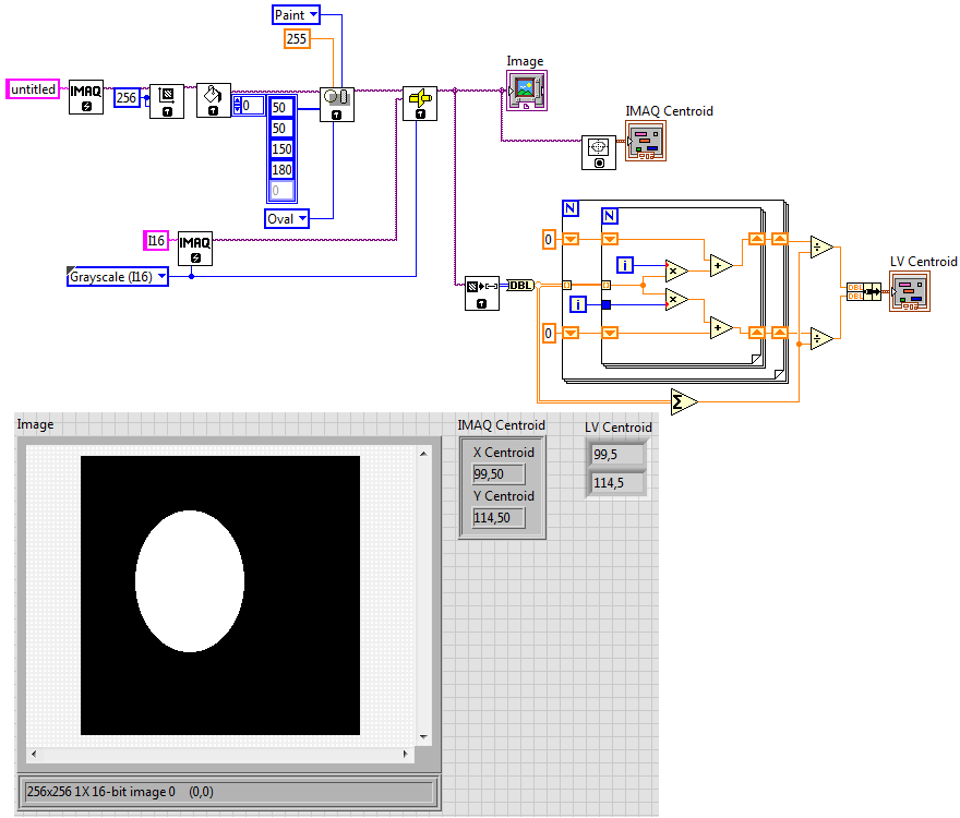
I have an image which is an int16 signed with no hanging mask (outwardly hidden). The center of gravity IMAQ vi reports the KING Center instead of the answer for the center of gravity. Why would he do that?
Steve_Block wrote:
You have a perfect image. The calculation of the centre of gravity works perfectly with a simulated Gaussian beam. This is when a real picture of a camera is used to ensure that the centre of gravity is calculated incorrectly.
Center of gravity is generally quite simple and straight forward - this should be independent of the content of the image.
If you get the feeling that, in some cases it calculates correctly, then you can calculate it with pure primitive LabVIEW something like that:
Compared to the IMAQ, it will be a bit slow, but you verify that centroid IMAQ calculated correctly or not for your images.
Andrey.
-
Center of gravity of a 2D array
Hello!
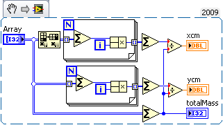
I want to do a sub - vi that calculates the center of gravity of the values in a table 2D (I32).
Entry:
2D-Array (I32)
Output
CentroidX (whole I32)
CentroidY (whole I32)
I found this code on the web:
FUNCTION centroid, array
Michèle = size (table /N_Dimensions)
Michèle IF NOT 2 before you BEGIN
Message, ' array must be two-dimensional. Back...', / information
RETURN-1
ENDIF
s = size (table, Dimensions)
totalMass = Total (array)
XCM = Total (Total (table 2) * Indgen (s [0])) / totalMass
YCM = Total (Total (table 1) * Indgen (s [1])) / totalMass
RETURN [xcm, ycm]
END
But I can't figure out that to Indgen() and Total().
You guys can give me some advice to help me on the way, it should be pretty easy.
THX in advance a Kudo will be given you!

First, in case you're wondering, the function's IDL. INDGEN as it is used, it generates an array of integers with each value is equal to its index. TOTAL (as you might guess) is the sum of a given table. The syntax can be difficult, unless you specify a dimension (1 or 2) of a 2D array, you get a 1 d array where each element is the sum on the other dimension. In this case, xcm has more columns than the sums of ycm on lines.
Knowing enough IDL translation LV gives me this:
-
Action/Script Photoshop to place the vertical line at the center of the Image
How to create an action (or a script) in Photoshop that creates a vertical line in the center of the page?
Here is an example of what I'm looking for.

First go to view > rulers, then right-click on the rule, and the percent change units.
(so the action registers per cent and will work on different size documents)
Then drag a vertical guide at the Center, drag one to the top of the image and the other down.
(the goal is so the online tool is aligned with the top and down and you know where is the center of the document)

For action, you can use the online tool and just save lines from the top of the image down along the center guide.


-
The Center vertically with text bullet points
CS6 in Windows 7. I made a custom point bullet which is a square, but it is aligned vertically with the bottom of the first line of the text rather than in the center of the first line of text. How to move the point upwards so it is aligned with the center of the first line of text?
Here is how it is now.

Thank you.
Mark
You can create a character style to apply to the ball which adds the vertical offset, or since you say that it is a custom chip, you can redo the ball and push it higher compared to the line when you do (which is a more universal solution).
-
How do I get my webscreen moved to the Center?
How do I get my webscreen moved to the Center? Everything has moved towards where I lose the right side. Even my desktop wallpaper is shifted to the right.
Hi Pennykriz,
View all moved right? Refer to your manual for the monitor, monitors have parameters go horizontal and vertical display, then you can be possibility to factory reset, or at least to change these settings.
I guess that you are on a desktop pc and not on a laptop.
I hope this helps.
-
Problem with the placement of components in the Center
I have the screen or full-screen and four ButtonField. How can I put buttons to this container in the Center (vertically and horizontally)?
I try to use the Field.FIELD_HCENTER flag. ButtonField.HCENTER | Field.FIELD_VCENTER | ButtonField.VCENTER for buttons, but they take only horizontal center
I struggled with this before as well. Here's what I found to work for a single centering element:
VerticalFieldManager vfm = new VerticalFieldManager(VerticalFieldManager.USE_ALL_WIDTH | VerticalFieldManager.NO_HORIZONTAL_SCROLL | VerticalFieldManager.NO_VERTICAL_SCROLL);

// Create a horizontally centered HFM
HorizontalFieldManager hfm = new HorizontalFieldManager(HorizontalFieldManager.USE_ALL_HEIGHT | HorizontalFieldManager.NO_HORIZONTAL_SCROLL | HorizontalFieldManager.NO_VERTICAL_SCROLL | HorizontalFieldManager.FIELD_HCENTER);

// Create a vertically centered label
LabelField label = new LabelField("Test", LabelField.FIELD_VCENTER);
hfm.add(label);

vfm.add(hfm);
add(vfm);
You should be able to extend this to do what you want to do with an another VerticalFieldManager.
T
-
Find the center of luminance or tone of an image?
I need a script that will take a photo convert to the * b * coordinates and give the x values and y below where m is 255.-l. It is the center of tonal mass. the image... The equations are described below, except instead of color barycenter substitute tonal Center. This is necessary for a document to the aesthetics of the pictorial composition. You'd get credit in the document.

use MatLab to solution
-
Coordinates of the point on the spline
Hi guys.
I'm banging my head on the wall for some time now, with this question.
As a simplified version, I have a perfect circle, and I need to find the coordinates of the midpoint between two vertices. In this case:
A is a summit which coordinates [0, 0]
B is a summit whose details [500, 0]
A1 is OutTangent from point A of coordinates [138,-138]
B1 is InTangent point B of coordinates [362,-138]
The goal is to find the coordinates of the midpoint.

Again, it is the very simple scenario. Other times tangent will be different lengths and forms will be so, at random, so I want to wrap my head around to find coordinates based on 2 summits and InTangents and OutTangents.
Thanks in advance.
UQg,
I think it works:
t =. 5; percentage along the path (between 0 and 1)
P0 = [0,0]; vertex 1
P1 = [138,-138]; tangent 1
P2 = [362,-138]; 2 tangent
P3 = [500.0]; Vertex 2
c = 3 * (p1 - p0);
b = 3 *(p2-p1) - c;
a = p3 - b - c - p0;
((un * t + b) * t + c) * t + p0
Dan
-
Preset to a registration mark in the center of the page
I can't figure out how to put my reg brand. in the center of the page to set up for printing! When I click on print and go to marks and bleeds and click the brands they want only the outside corners and there is not a preset (that I can see) who puts at the Center. Help, please!
Generally, marks reg. are outside of the print area. If you need within the area of the page, you will need create your own. You can create the mark from the register, like any other work and assign it to the color of "Recording" by default in the swatch Panel.
To put something in the center of a given work plan:
Either:
- Cut the work or items (Cmd - x)
- Zoom in on the artboard (cmd-0)
- Paste (Cmd - V)
Or:
- Select the item of work
- Choose "Align to the work plan" in the pull down menu in the options bar
- Click on the 'Horizontal Align Center' and 'Vertical Align Center' buttons in the options bar
-
JS - selection of the center of the artboard / New Document with some dimensions of the artboard
TL; DR:
How do I Center my current selection to the artboard?
as well as hitting the "align horizontal center" and the «align vertical center» buttons
Hello
I searched for the last two hours and before my head hit the keyboard I wanted to ask for help.
What I am struggling with:
in my init function, I create a new document and then copy all the layers of the previous document step by step to the new document and then save it as SVG.
Init
(function() {}
Destination = Folder.selectDialog ("selecting a folder for files SVG.', docPath");
If (! destination) {return ;}
holderDoc = app.documents.add ();
stepThroughAndExportLayers (docRef.layers);
}());
My problem is that holderDoc = app.documents.add (); always creates a document that is not the same size as my original document where the layers are copied from.
so, I want the same artboard size as in my original document.
I am fine with the fact that fixed values or directly take the values of the initial RFSO.
I tried this on the segment where I create the new document:
Init
(function() {}
Destination = Folder.selectDialog ("selecting a folder for files SVG.', docPath");
If (! destination) {return ;}
holderDoc = app.documents.add ();
holderDoc.artboards [0] .artboardRect = [0,0,128,128];
stepThroughAndExportLayers (docRef.layers);
}());
and receive this error message:
"Error 1200: Illustrator error: 1346458189 ("PARM").
Online: 83
-> holderDoc.artboards [0] .artboardRect = [0,0,128,128]; »
what I read on the web means that illustrator does not know what to choose document. but I called him directly. so, what could be the problem?
to clearify: I don't want to adapt to the artboard for the images/layer. the work plan must always be a certain size. (for me 128px by 128px)
Thank you for helping me to each fixing of my approach highly or offer a completely new.
Thank you very much in advance.
Edit: workaround solution
(function() {}
Destination = Folder.selectDialog ("selecting a folder for files SVG.', docPath");
If (! destination) {return ;}
var activeArtboard = app.activeDocument.artboards [app.activeDocument.artboards.getActiveArtboardIndex ()];
var ABRect = activeArtboard.artboardRect;
holderDoc = app.documents.add ();
holderDoc.artboards.add (ABRect);
holderDoc.artboards.remove (0);
holderDoc.artboards.setActiveArtboardIndex (0);
stepThroughAndExportLayers (docRef.layers);
}());
now, I added a new work plan to the new document with the same size as the work plan on the original document.
I have remove the work plan predefined on the new doc and the new work plan as active.
BUT!
now, the work plan is not centered in the window. Illustrator that allows to place my image with ctrl + c-> ctrl + v somewhere outside the artboard.
Now I need to align my selection in the center of the artboard. but I can't find any reference on how to Center a selection to the artboard.
I don't know if I understand you right.
If you want to create a new document with a fixed width and height, you can do this:
var doc = app.documents.add(DocumentColorSpace.RGB, new UnitValue ("128", "px"), new UnitValue ("128", "px"));If you want to only align your objects selected on the artboard, you can try this:
Note that the result may be different, if the clipping masks are exist in the document.
Please test it first on copies of your documents. Use it at your own risk.
// ArtboardCenterAroundSelectedPaths.jsx // works with CS5 // http://forums.adobe.com/thread/1336506?tstart=0 // (title: script to align selected objects to artboard) // quick & dirty, all selected items will be centered at the active artboard // (include clipping paths !visible result can be different) // regards pixxxelschubser 19.Nov. 2013 var aDoc = app.activeDocument; var Sel = aDoc.selection; if (Sel.length >0 ) { var abIdx = aDoc.artboards.getActiveArtboardIndex(); var actAbBds = aDoc.artboards[abIdx].artboardRect; var vBounds = Sel[0].visibleBounds; vBounds_Li = vBounds[0]; vBounds_Ob = vBounds[1]; vBounds_Re = vBounds[2]; vBounds_Un = vBounds[3]; if (Sel.length >1 ) { for (i=1; ivBdsI[0] ) {vBounds_Li = vBdsI[0]}; if( vBounds_Ob < vBdsI[1] ) {vBounds_Ob = vBdsI[1]}; if( vBounds_Re < vBdsI[2] ) {vBounds_Re = vBdsI[2]}; if( vBounds_Un > vBdsI[3] ) {vBounds_Un = vBdsI[3]}; } aDoc.artboards[abIdx].artboardRect = [vBounds_Li +((vBounds_Re - vBounds_Li)/2-(actAbBds[2]-actAbBds[0])/2), vBounds_Ob -((vBounds_Ob - vBounds_Un)/2+(actAbBds[3]-actAbBds[1])/2), vBounds_Li +((vBounds_Re - vBounds_Li)/2-(actAbBds[2]-actAbBds[0])/2)+(actAbBds[2]-actAbBds[0]), vBounds_Ob -((vBounds_Ob - vBounds_Un)/2+(actAbBds[3]-actAbBds[1])/2)+(actAbBds[3]-actAbBds[1])]; } } else { alert ("No selection"); } Hope this is useful for you.
Have fun
-
Correction of the goal out of the Center
Please excuse me if I'm missing the point. I wanted to ask a question on the Lens Correction in Camera Raw that had bothered me, as I looked in the customization of the PCL files.
One of the parameters in the format of LCP file is ImageXCenter (and ImageYCenter). The default value of 0.5, which I guess means ' to Midway through the image ", that is, dead-center. Is this coordinate the base to the center of the distortion or tile, or chromatic aberration, all three adjustments?
I appreciate that the lenses are not perfect, and that the imperfections can be biased. But these imperfections would be identical across many copies of the same lens - that is (for example) could all the 50 mm/1.4 lenses have the same X / Center's contact information?
On the one hand, it is possible that the manufacturing process of a particular lens produces also asymmetrical results; However, the process could produce lenses that are roughly symmetrical, but with slight variations from all sides. I don't know, I don't do lenses, and I'm not used to measure their flaws.
Then, is what confuses me - while I understand the usefulness of the coordinates of Center in the profiling of your own lenses - is it wise to Adobe to provide profiles of biased target coordinates to the general public?
As I have explained earlier, the optical center of a lens does not necessarily correspond with the center of the image (even if a lens is perfectly centered around its own planned optical Center). This is systematic behaviour (i.e., no-unit of behavior). In other words, you can calculate the value center for multiple units of the same lens, their average together and get something different from 0.5.
Eric
-
Travel/table grid of squares all toward the center of the document?
Hi all.
We are working on a file that consists of a wide range of small squares.
I was wondering if it is possible to move all of the squares to the center of the document... a script, or simply a method.
Any ideas or suggestions would be greatly appreciated.
Thank you!
Best,
Don
Hi Don, I realized that the first script is only set up to manage 20 lines, so I modified it manages 120 lines, hopefully this should be sufficient.
function main(){ if(!documents.length) return; var win = new Window('dialog','Space Layers'); g = win.graphics; var myBrush = g.newBrush(g.BrushType.SOLID_COLOR, [0.99, 0.99, 0.99, 1]); g.backgroundColor = myBrush; win.p1= win.add("panel", undefined, undefined, {borderStyle:"black"}); win.g1 = win.p1.add('group'); win.g1.orientation = "row"; win.title = win.g1.add('statictext',undefined,'Space Layers'); win.title.alignment="fill"; var g = win.title.graphics; g.font = ScriptUI.newFont("Georgia","BOLDITALIC",22); win.g5 =win.p1.add('group'); win.g5.orientation = "row"; win.g5.alignment='fill'; win.g5.spacing=3; win.g5.st1 = win.g5.add('statictext',undefined,'Horizontal'); win.g5.et1 = win.g5.add('edittext',undefined,'20'); win.g5.et1.preferredSize=[50,20]; win.g5.st1a = win.g5.add('statictext',undefined,'px'); win.g5.st10 = win.g5.add('statictext',undefined,''); win.g5.st10.preferredSize=[55,20]; win.g5.st2 = win.g5.add('statictext',undefined,'Vertical'); win.g5.et2 = win.g5.add('edittext',undefined,'20'); win.g5.et2.preferredSize=[50,20]; win.g5.st2a = win.g5.add('statictext',undefined,'px'); win.g15 =win.p1.add('group'); win.g15.orientation = "row"; win.g15.alignment='fill'; win.g15.spacing=10; win.g15.bu1 = win.g15.add('button',undefined,'Space Layers'); win.g15.bu1.preferredSize=[150,30]; win.g15.bu2 = win.g15.add('button',undefined,'Cancel'); win.g15.bu2.preferredSize=[150,30]; if(version.substr(0,version.indexOf('.'))<10){ alert("Sorry this script is only valid for Photoshop CS3 or higher"); return; } win.g5.et1.onChanging = function() { if (this.text.match(/[^\-\.\d]/)) { this.text = this.text.replace(/[^\-\.\d]/g, ''); } } win.g5.et2.onChanging = function() { if (this.text.match(/[^\-\.\d]/)) { this.text = this.text.replace(/[^\-\.\d]/g, ''); } } win.g15.bu1.onClick=function(){ if(win.g5.et1.text== ''){ alert("No horizontal pixels entered"); return; } if(win.g5.et2.text== ''){ alert("No vertical pixels entered"); return; } win.close(1); spaceMasks(Number(win.g5.et1.text),Number(win.g5.et2.text)) } win.center(); win.show() } function spaceMasks(spacingA,spacingD){ var startRulerUnits = app.preferences.rulerUnits; app.preferences.rulerUnits = Units.PIXELS; var selectedLayers = getSelectedLayersIdx(); if(selectedLayers.length <2){ alert("Not enough layers selected!"); return; } var boundsList=[]; var tempbnds=[]; showFX(false); for(var a=0;a


Maybe you are looking for
-
Unable to connect to the AppStore - tried all the patches
Hi all, cannot connect to the App Store on my iPhone 6 running ios9.3.2 I did a lot of research and have tried a variety of bugs including: log out and back in again change in the weather from automatic to manual and vice versa activate Touch ID then
-
Error code 0x80070005 loading SP2
When loading SP2 for Vista, I get an error code 0 x 80070005. I can't load Windows Live Messenger upgrade until I have service pack 2 support. What can I do?
-
I get an erroe OX643 code when you try to update net framework 3.5 service Pack 1
I bought dragon naturally speaking premium 11.5 version when you try to install the software, it is significant that I need to update net framework net framework 3.5 service pack 1. I always get the error message about the failure of the update. I ge
-
After I shut down the computer, he re boots itself after 5-10 minutes.
After I shut down the computer, he re boots itself after 5-10 minutes. Weird. I tried to change the settings. Can anyone suggest anything?
-
Fields of rotation and repaint
Hello I am currently having problems with a screen that I develop, I run a my own implementantion of a textField that basically stretches from textField but excludes a height and width figures and therefore attracts. The problem is that I overloaded