NEITHER 9234 with quasi static analog voltage
Hello
I have a NI 9234 (4 channels + / IEPE 24-bit 5V) attached to a chassis cRIO module. This module is ideal for accelerometers and microphones where the tension is in constant evolution (ie; measures of variation rates).
I also have a module OR 9237 (4 channels 24-bit full-bridge module analog input) attached to the same cRIO. This module is ideal for measure variable voltages of strain gauges (quasi static and dynamic loads).
The attached graph shows the two channels, collected synchronously, but as you can see the (red trace) cell breaks down (as it should), but then drifts back to zero on its own, when in fact it should remain low just like the extensometer is beam. After all, the two sensors are physically secured.
Q1: Would that have something to do with AC/DC module 9234 internal coupling?
Q2: Is it really possible to collect "quasi static" ongoing tensions by using a NI 9234 module?
No explanation as to why this occurs, or if there is a way to remedy this would be appreciated.
Kind regards
Andreas
Coupling AC/DC must do a lot with your question. In mode AC voltages static will be fitered outside and the 9234 measure indeed only change voltages. In DC mode, the voltage goes directly to the AD converter and you can also detect static tensions.
A minute of Googling gave me the answer, this load cell electric piezo can measure dynamic changes, as any charge will escape the path the lowest resistance and the signal will go to zero after a certain time. I guess the other device you were using higher internal resistance (which is relatively low on the 9234), so it takes more time to what he flees, but he also took on the picture you attached your second try.
Here you can find more example under the title
"WHY ONLY DYNAMIC FORCE CAN BE MEASURED WITH SENSORS OF POWER PIEZOELECTRIC"
http://www.PCB.com/techsupport/tech_force
Andreas Jost
Technical sales engineer
National Instruments
Tags: NI Products
Similar Questions
-
Helps with 7852R input analog voltage measurement
Hello
I'm trying to measure three signals of tension off a QPD, the three signals are connected to the IA the SCB - 68 and then I used the example of vi to acquire analog inputs with FPGA R in the finder of the example. However, I make a range of very large numbers. I don't know how to convert these volts or what are these numbers, units... etc.
Any help with this, please?
Thank you
Hi Biochemist_MU
Please take a look at the forum post FPGA of analog input and output scale. It deals with the scaling of the R-series cards.
Hope this helps and let us know if you have any other questions.
-
Generate an analog voltage with amplitude variations
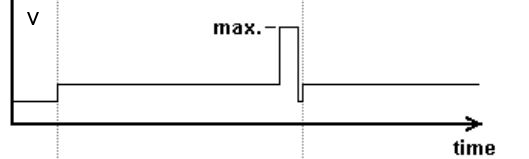
I want to generate a 0 - 5V analog voltage output that has a variable amplitude, as shown in the figure. The maximum voltage is 5V and low voltage a percentage of this, but I must not vary the amplitude during execution of VI.
With digital outputs, you are limited to two levels. Low and High. (1 and 0). Here are the outputs of the DIO lines as DC voltage levels. The two levels can be anything, but 0v is most commonly used for bass and 5v is used for the great. This is called (as well as some other features) TTL logic.
There are some cards that allow you to choose the digital voltage levels, but your all-in-one does not provide this functionality.
You could do something similar with digital, where you have only used the 0v and 5v levels.
You are absolutely right that software control timing is less precise than the timing control material, however, if you did a spot of digital output in this way and set it up to do the finished samples or continuous, it would use a material timing and would therefore be very accurate (in accordance with the specifications in the technical data of the device).
-
Error 50103 - simultaneous analog Vout and wine with start of analog triggering
Hello
I'm stuck error 50103. I looked on the Web site of NOR and worked through the 7 cases and think that my problem is the 6 case - although I'm not sure - and have no idea how to fix this. Basically, what I would do is out my signal and have receive side save after it passes through a noisy channel. To start, I have attached a trigger control so that the transmission or recording start before the input trigger exceeds a certain value (in my case, 3V).
Could someone please look at my code (attached, called 'Optical_DPPM_V3.vi')) and try to give me an indication as to what I'm doing wrong? Thank you!
Furthermore, I use examples of OR that I have also included in the .zip for reference file.
SP
P.S. hardware: LabView 8.2, NI PCI-6070E
Hi gt3000,.
Thanks for your reply. I actually solved the problem I called one of your offices directly and spoke with someone last night.
Indeed, the problem was "case 6" as it is stated on the page you gave. "." When I spole with one of your colleagues, I was directed to an example that does most of what I wanted. If anyone is interested, you can follow this path to find:
Help--> find examples--> material input and output--> DAQmx--> synchronization--> multifunction--> multi-function Synch AI - AO.vi
It seems that the trick is to use an internal digital triggering to synchronize the CLK for VI and VO.
If people are interested, I can send my final code around for a differential pulse modulator, triggered by an external analog voltage which the receiver registers and stores the values in a worksheet. My next goal is actually write the code for the receiver to demodulate information... here go us!
Thanks again,
SP
-
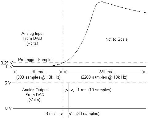
I am working with a combustion chamber and using a system of data acquisition (with the hardware OR SCB - 68) to read the pressure in the cylinder (such as analog voltage). I'm trying a pulse delayed, 1 millisecond to 5 volts of output once the pressure in the cylinder is high above 5 bar (which corresponds to an analogue voltage of 0.25 V). I would also like to record 30 ms samples before the trigger and 220 ms samples after the outbreak. The following image shows visually what I'm talking about.
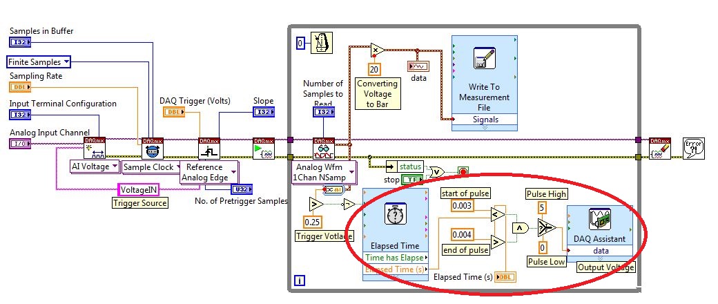
I created a LabVIEW VI (which is attached), but I keep running into 2 issues:
- When I run with samples finished after a period of time, I get error-200281which I don't quite understand.
- Using the Express VI 'Out of time' to keep time for the pulse I can not get a resolution of 1 millisecond, the pulse is not generated when I put the window between 0.003 and 0.004 seconds for high pulse (i.e. the resolution of 'Elapsed Time' seems to be too coarse).
I'm a beginner to LabVIEW sorry if my questions are trivial or my VI makes no sense, but I was stuck on this during more than a week. Any help would be greatly appreciated!
Thank you
Morgen
This isn't a good way to trigger a pulse.
Use a trigger DAQmx to send the pulse when your acquired signal exceeds 250 mV you specified.See this for DAQmx trigger:
-
is it ok to connect two outputs analog voltage in series?
Ok... I have a PS-210 FieldPoint... basically an analog voltage output 0 - 10V, 200mA per channel (with additional external power supply)... my question is... can I plug two channels in series? Love how I can put two AA batteries in the series... and then to double my blood pressure? and then check my two separate channels and the sum of the tensions would be assujettirait I have my load in?
Thank you!
No, you can't. The channels all share the common side of their outputs. If you've tried to hang them in the series, you have wind of short-circuit one output from the ground.
The reason for which you can do with batteries is that the tensions are floating. There is no common reference between the negative terminals of both batteries.
-
Tension AC with DAQ card analog interface
Dear all
My sensor gives the alternative of 200mV analog signal tensions. Can I get these tensions on LabVIEW using the NI 6281 DAQ board. (I've already acquired 100mV DC analog voltage signal which came from another sensor using the same card and I use port 66 and 33 for this signal). Can I adopt the same procedure and using the same ports?
Waiting for your response.
Kind regards
Automata
Yes. Since this is an alternating signal, simply measure at a high enough frequency of acquisition to represent your signal.
-
Hello
How acquire and store the values of voltage DAQmx?
I tried several code example, but they can't get the chart. I don't want to chart. I want to measure exactly the analog voltage values and record these values - as an excel chart, that contains the selected channels and voltage values.
What the example code that I can use?
My hardware is NI PCI-6251.
Thank you very much.
-
Get the duty cycle of DAQ to analog voltage input module
Hello.
I'm new to labview. I have an analog voltage input data acquisition module. I try to get the duty cycle of a square (generated from a function generator). What is the best way to go about this? When I use the vi to acquire an analog wave cyclical report, the values are incorrect.
Post your VI as well as real data of your signals so we can see what is happening.
Lynn
-
Trigger SW analog voltage CONT Acq & graphic
Hello
In the example Cont Acq & chart analog voltage SW Trigger.vi It seems to me that if specify you a channel that relaxation comes on, then it would be a hardware trigger is not a software trigger. Why do call it a software trigger work?
I PCI6071E I want to trigger by sending in a channel if a pulse (63). Wouldn't that considered triggering material? If that is an example for this available?
Also I'm not clear on what they mean by the parameter ' Amplitude/hysteresis window' in the trip parameters. Could someone explain this to me?
Thank you!
-
Show data as a percentage of column with a static table
Hello
I have a problem of calculating one percent in a table. I have two columns in the criteria tab:
Departments and degree
I need an extra column % calc total departments for each Department. I know that I can do with PivotTable, create a new column and put: view-> data as per cent of-> column but I do with the static table.
Is possible to do?
Thank you!!!Alex,
You can try the following example here:
http://www.biconsultinggroup.com/knowledgebase.asp?CategoryID=198&SubCategoryID=364
by using the sum (measure of the size attribute)
This should give you access total general in the report in a column, you can drift % of.
HTH, if it is correct, please mark answered / reward points, as you see fit to do!
Alastair -
Blocking of blue screen with the analog voltage (WinXP, PCI-6251)
Hello
I'm looking to solve a problem of blue screen with my measure blocking
application, which I am developing with C++. Blocking seems manifest
a little random after a variable amount (500-50 000) of voltage analog
measures. My application needs to make a huge amount of these digitally
trigger voltage measures after a certain period of time, and I'm using a
unique
task to do. The task is stopped and started after a single measure
is
which is done around 10 000 - 100 000 times per second. For this
because I do synchronized with the PCI-6251 map data acquisition and
one
Ztec oscilloscope card. It seems that the probability of blocking could be
associated with
the frequency of measurements of voltage that I perform.The
the app itself is multithreaded, but I'm blocking concurrent access
TO
the card with lock - all access to the card are behind a single mutexlock, so simultaneous access is blocked. In any case, all data acquisition
access
o the map is initially a single thread, which is dedicated to the acquisition of data
operations.I also did stress tests with Ztec scope map, which does not
result
in all the problems. I also disabled in order of acquisition of Ztec map data
TO
Make sure that it wasn't the card scope, the origin of the problems - the problem
persistent, so this seems to point towards the direction of the nidaq map.The deadlock appeared when I used the original supplied with drivers
the
card. I installed the latest drivers (removed the device from)
' Windows
Device Manager and your application Measurement & Automation, reinstalled), but the blue screen still appears.Blue screen gives me a few debug data, but it does not mention any
files .dll or something that would be of course point to a specific file (driver). I enclose at least partially matching code snippets.
Hello again! I've been in contact with a local support person, who suggested that I have use DAQmx_Val_FiniteSamps instead of DAQmx_Val_HWTimedSinglePoint. I don't have any other changes, but this (see below) and the problem disappeared, so this seems to be an acceptable solution, because I don't see at all why not do this way. (Thanks Henry!)
DAQmxErrChk (DAQmxCfgSampClkTiming (task_reader, NULL, 100000.0, DAQmx_Val_Rising, DAQmx_Val_HWTimedSinglePoint, 1));
DAQmxErrChk (DAQmxCfgSampClkTiming (task_reader, NULL, 100000.0, DAQmx_Val_Rising, DAQmx_Val_FiniteSamps, 2)); -
Covered wagon with an average of analog voltages DAQmx
I searched through screws, I can't seem to find something that will automatically average numbers of boxcar fed into it. I am trying to create a feature of my software that will allow the dynamic configuration of the car covered with an average of some inputs. I would like to avoid hard-coding tables which are filled/rotation etc etc.. Any help is appreciated
Thank you
If you use a Functional Global to store the values and call that VI of two different screws, you will access the same data. You could use two Global in the functional shift registers and use a selector to place / extract data from / to the appropriate shift register. Only VI call access one commune VI at the time, so one of the caller of the screw will be 'blocked' until the first caller is done. This does not usually work for data acquisition applications high speed.
You might consider using named queues instead of functioning overall. You might be interested in this thread on the forums of LAVA that deals with boxcar implimentations. You create a queue for each data stream and can perform functions such as "preview" queue to get all items without actually removing them from the queue. If you use a LabVIEW 8.6, there is a new feature called with loss of queues. You set an upper limit on the size of the queue and "lossy enqueue" allows to add items at the end of the queue. If the queue fills up, then the oldest data element will be lost.
-
I have a NI 9234 inside a cDAQ, and I was wondering:
Can I configure each channel individually, while measuring the two at the same time?
I want to have the excitement of 2mA enabled on a channel, but not the other I read / compares the two signals simultaneously.
So far, I have to choose Toggle both on a property node, and not what I need.
Thank you
Billy Murphy
I thought I'd share this email, I just returned from a very helpful employee at NOR :-)
-Billy
William,
You can of course! Please take a look at this article:
http://digital.NI.com/public.nsf/allkb/3AD6CCE935192B4086256F6B0079CB1F?OpenDocument
The last paragraph is the most relevant: If you want to have different settings on each channel used, the best thing to do is to create a channel DAQmx of different types of measurement for each of your different settings. These different channels DAQmx can always be used within a single task DAQmx. For example, if you have three starters of micro and single voltage, you can create a type of measurement microphone and a type of tension using the DAQmx create channel VI. The channel will be associated with three physical channels while channel voltage will be associated with one. Voltage channel can have different settings, factors, coupling, the fat and IEPE properties compared to the microphone channel.
Concerning
Katie Maddox
Technical sales engineer
National Instruments
-
Static analog output without a while loop?
Hi all
Would like to know if it is possible to set up a card outputs analog instrument (with DAQmx I presume) to have a static/continuous output, without needing to use a while loop. I what would want to return a single value rather than a table or a waveform. It would be similar to option for digital IO cards to have static strings instead of strings of waveform. In the examples I've seen, he always seems to be a time loop is necessary, even if the channel is configured for a single sample, but I think it would be cleaner and easier to control dynamically without the loop (particularly if I run several screws in parallel). My particular application is to configure inputs and outputs analog, then runs different tests with other maps of the instrument. Please notify. Thank you.
GSinMN
No, you don't need a loop. A writing DAQmx for 1Sample game, it's all you need. Please include am image of the pattern block one of these examples. My guess is that the example is simply a way to accept changes in production without having to re-run the whole VI.
Maybe you are looking for
-
Microsoft Finance scam - refund Department Possible
I got three calls pressing me to access my computer to pay back me the money paid to a company of tech support for one year. The appellant says that the work of the company to Microsoft, but it is not Microsoft. The appellant said that it is from the
-
Queues offline: If an application is an html form, store .htaccess locally or on the server?
The users of my application will be filling out the form offline more than 90% of the time. If they start the app/form offline, would be the .htaccess file be stored locally (and compiled with the app?) or on the server? Thank you! Sorry for such a s
-
Get the serial number for Windows 7 after formatting
I bought Windows 7 online less than a year ago. I need to format my hard drive and before I do, I need to know the serial number to reinstall windows. How can I do?
-
What was wrong in my way to download windows7?
-
Crashing, freezing and 100% use disk
HelloI had my laptop for a little over 2 years and use it on a daily basis, with only the battery being replaced in its lifetime.Recently my drive CPU was at 100% usage causing accidents, freezes and finally the frustration as well as downloads ot n9