Custom Error 200077 of scale
Hello
I have a cDAQ-9188 chassis and seven modules. My VI consists of an acquisition of data-Assistant to acquire signals. With this, I created a channel "Luftdrucksensor". For benchmarking, I used a Custom Scaling in which I created a characterisitc curve. My sensor has a range of output of 4-20 my and 0, 9-1, 1 bar. But when I want to start measurement, that an error occurs.
Can you help me?
Thank you
Concerning
The min and max must be based on the value on the scale, not the 4-20ma without scales.
Tags: NI Hardware
Similar Questions
-
9237 with deck full load cell: support cell_null_off_shuntcal.vi survey error 200077
Normal
0fake
fake
fakeEN-US
X NONE
X NONE/ * Style definitions * /.
table. MsoNormalTable
{mso-style-name: "Table Normal";}
MSO-knew-rowband-size: 0;
MSO-knew-colband-size: 0;
MSO-style - noshow:yes;
MSO-style-priority: 99;
MSO-style - qformat:yes;
"mso-style-parent:" ";" "
MSO-padding-alt: 0 cm 0 cm 5.4pt 5.4pt;
MSO-para-margin-top: 0 cm;
MSO-para-margin-right: 0 cm;
MSO-para-margin-bottom: 10.0pt;
MSO-para-margin-left: 0 cm;
line-height: 115%;
MSO-pagination: widow-orphan;
font-size: 11.0pt;
font family: 'Calibri', 'sans-serif ';
MSO-ascii-font-family: Calibri;
MSO-ascii-theme-make: minor-latin;
MSO-hansi-font-family: Calibri;
MSO-hansi-theme-make: minor-latin ;}Hello
I'm trying to use the example
load_cell_null_off_shuntcal.VI with a scale of full-bridge (Honeywell
Model 31, not amplified). I'm using LabView 8.6, cDAQ-9172 and NI9237. The
load cell is connected to the pins 2,3,6 and 7.Entries for the front side of the VI
are: excitation10V internal; mV/V 2.1492 (calibration sheet); weight max 10
lbs; resistance bridge 350 ohms (Honeywell specifications); 9237 shunt internal
100 kohm resistance; map of shunt R4 (default setting). I chose
"Do not offset null" and "shunt cal.This is the error I get:
Error-200077 occurred at DAQmx
Do a calibration Shunt (bridge) .vi:1 or the possible reasons:Measurements: Requested value is not
support for this property value.Property:
AI. Bridge.ShuntCal.GainAdjustYou asked:-61.980405e3
Valid values begin with: 500.0e - 3
Valid values ending with: 1.500000
If the "shunt cal.
green button is not selected, there is no error. I understand that the Gain
Change value should be approximately 1, whereas I get is much larger. The Subvi DAQmx PerformShuntCalibration
.VI (bridge) contains a "Call library function node" which I did not
find out how interrogate.Someone else has experience
with this error? Do you have any advice on:1)
How to 'see' the calculations being
carried out inside the "call library function node"?2)
What the correct shunt element
a full-bridge load cell location is? (although changing this location only)
does not eliminate the error, I can't find this info).3)
What can I do wrong with
my entries to cause this error?Thank you
Claire.
Hi Claire,
You must physically connect the SC of arm of the bridge terminals (normally R3). The terminal is not provided for the connection of external resistors.
See the example
C:\Program NIUninstaller Instruments\LabVIEW 8.6\examples\DAQmx\Analog In\Measure Strain.llb\Cont Acq strain samples (with calibration) - OR 9237.vi
-
NEITHER 9205 in a task; error-200077
I'm trying to set up a task to read all 16 channel differential on a NI 9205.
I get an error-200077 when I get to add channel8 (from count to zero) to the task, almost as if the software
It's an e-mail with asymmetric 16-8 differential channels, not 32/16 like in reality.
Anyone, no matter what?
Use AI0 - 7 and HAVE 15-23
AI8 is the - side of AI0
-
Range of custom error codes and error rings/Labview 2013 SP1
Hello
for the error message personalized codes there are these assigned ranges:
-8999-by-8000
5000 to 9999
500 000 to 599 999If I create an "error ring" in Labview 2013 SP1, then I am able to choose predefined error codes or I can put in some custom error codes. Curious as I was I chose 'Labview' in the menu drop down and looked up some error codes. I noticed that there are some affected error codes that are of the order of custom error codes (see attachment) of 538170 to 538193.
Is this a bug or feature? What is the impact if I defined error codes customized with identical, already existing error codes?
Kind regards
Thomas
Thomas,
It seems you have installed ModBus library. As it is an additional package, picking "custom error codes" is not bad even if the library fits in LV...
Norbert
-
error-200077 when you deploy the SysDef file
I added PXI-6704 as a data acquisition device in my system definition file. When I try to deploy it, I get:
"error-200077 the requested value is not supported for this property value.
The module has 16 channels voltage (+/-10 v) and 16 current channels (0 - 20ma) so I set in the dialog box "create DAQ hardware" as type MIO with 32 channels AO.
If I delete the device from the system definition, it will deploy without error.
VeriStand 2011, computer host is running Windows 7, controller RT PXIe-8133.
Has anyone seen this error?
Hi PMAC,.
This error will occur if you do not select the option 'Disable clocked by one-time support for the analog output material' during setup of data acquisition under the definition of your system. I've attached a screenshot of that. The reason you need to activate this box is that the 6704 only supports the clocked by the Analog i/o software, as explained in the manual.
You will also need to go into the output channels 16-31 and manually change each channel of current Type and the high level of 0.02 and the low level of 0.00. Once configured properly, everything should work fine.
Best,
Dan N
Technical sales engineer
National Instruments
-
Hello
I'm trying to control the timing of a timed loop. So far, I have tried several approaches via the software and which worked very well except the time loop in some missed cases 1-2 Ms I want to make sure the timing is right. I tried to provide an external clock through the acquisition of data I. The system I use is NI USB-6212. It has two counters and DIO and AIO, but I keep getting errors. I tried two different approaches. One was to use directly the game 'DAQmx create calendar Source.vi' in frequency mode, and when I did, I got error 200077. Then I found a post of somone saying that sometimes it is not possible and an alternative method is to use the same vi but set task of loop control mode. This one gave me Error200452. For this one you will see in my attachment the suggestion was to use an AI then the moment of him and then use this task for Creat DAQmx synchronization Source.
I don't know what the problem is or if I need to put something differently.
Please let me know if you can help me with this.
I'll try to continue to work on that, but if anyone of you a suggestion I'll be very happy to consider the issue.
Thank you in advance,
Best, Massimo.
Massimo,
In my view, the errors that you see are the result of your hardware USB-6212 is supporting the functionality of the task control loop. I have a M Series PCI card that is capable of operating both of your screws attached without problem (although they still +/-1ms variation on occaision). When I try to use a USB-6212 simulation, I get the same error codes that you do. Unfortunately, it's just a case of a lack of equipment.
Kind regards
-
Error-200077, USB-6008, deterministic application
Hello
I acquire and generate analog signals using a device USB 6008 to achieve control of feedback. I use a loop of simulation to generate the output of the controller, so need to synchronize signals input/output with the calculation software. I have the following questions:
1. when I use a sample for the analog output clock, I get an error (-200077). What is the cause of this error and are there solutions?
2. what values of step size and calendar period (simulation loop settings) should I use to ensure that determinism?
Your comments are appreciated.
Thank you.
The 6008 doesn't have a clock output. It's software timed and so not deterministic.
-
Executable cannot find the custom error code file
I'm building a LabVIEW 2013 application on a Windows 7 computer and deploying it to a Windows XP computer. My application has a custom error code file, stored in
- - errors.txt, but my executable on the Windows XP machine can't find the custom error file and returns only the string of appeal for all errors that occur. When you use is not an installer, I tried to copy the error code at all locations listed here: http://digital.ni.com/public.nsf/allkb/6077DBEDA4F9FEE3862571F600449501 but the application still does not load the custom errors. I have the box checked to "Error Codes customized Include" in the construction specifications.
When an executable of construction and the development of Windows 7 to XP, where do I put the custom error code file? It is found in Program Files (x 86), but find not because it's XP?
It's been a few months that I posted this question and I do not know if someone cares about this track, but the solution I found was to put the custom in
error code file \National Instruments\Shared\Errors\English\ There are other places that the runtime will look for the custom error codes (I tried all the ones listed above), if the same error codes exist in 2 places the error popup will appear two error messages. Error default 1, it looks like:
LabVIEW: An input parameter is not valid. For example if the input is a path, the path can contain a character not allowed by the operating system such as? or @.
=========================
NOR-488: Command requires GPIB controller charge controller.So if you have a custom error code file and it is available in 2 places that LabVIEW RTE check error codes, you will get the same message before and after the =.
List the error as "still included" file when building the executable or by checking the box to include files in error did not tour, obviously. Unless you create a Setup program to distribute the application, the error code file must be moved manually. Shared\Errors file works best for me because it's a place that makes sense.
Also, don't worry - it doesn't me taken 5 months to understand this point, I do not update all my loyal followers (ha) with a solution.
-
Hello
I am trying to run the test project that I found under the base NOR-DAQ\Examples\Visual 6.0\Analog to read an analog input, but I'll be back the code error-200077.
I use a USB-6003 card, with the driver OR DAQMX 15.0 and Vb6 worm, the problem is to located to play DAQmxReadAnalogScalarF64.
The sample project for digital reading seem to work correctly.
Thank you very much in advance for the support
Hi AndreaFerro,
have you tried to take a look at this KB?
Why should I get error-200077 with example for Visual Basic 6.0 and DAQmx programs?
http://digital.NI.com/public.nsf/allkb/0332E1EE7081091D862570360030C9F4?OpenDocument
I hope it solved the problem!
-
USB-6009 slow output signals using SignalExpress - error 200077
We have a Council of USB-6009 and Signal Express version 3.5.0
We want to generate low-frequency, analog and digital outputs to simulate some slow movement process.
We have created the signals and their generated as output, put when we RUN the project, we get error 200077, which seems to indicate that we must use On Demand distribution of signals.
If we choose On Demand, then the generate DAQmx says we have a missing entry.
So, what method should be used with the slow USB-6009 to generate box (.01Hz and slower) analog and digital outputs?
These are 2 of the projects, we tried - using On Demand, N samples, continuous, internal, and external triggering etc..
Thanks adavance for your help...
Welcome to the forums of Steve,
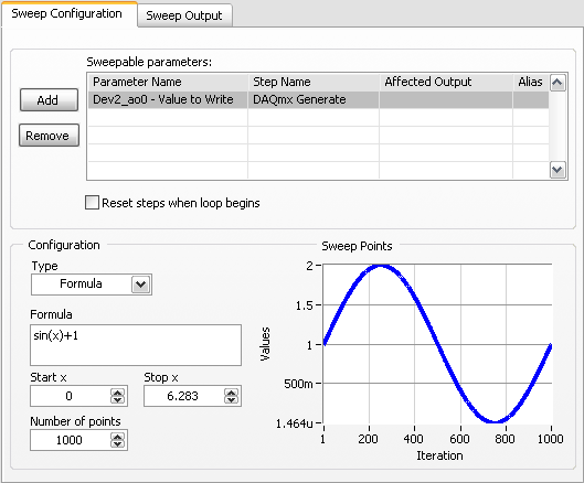
I have good news for you. I played a bit with the sweep and actually got a code facing up to generate a slow signal. I went and tested it with the 6009 and he was able to run without any errors. I joined here, but if you have to open (or anyone else in the future), here are some screenshots of how it works. If this works, feel free to make the forum as resolved while others can locate a solution a little easier in the future.
Scan Configuration:
DAQmx Config:
-
What is error-200077 and why it doesn't apply to one of my devices?
I have been using the following code as a test for the release of the fast digital signals and it works fine when I use my PCI6229. However, when I run the vi on my PCI6723, I get the message error-200077, which according to me is telling me that I can't use a sample with digital clock. Can someone tell me why this is and if there is a way around it?
See you soon
G
This unit is probably not capable of timed material e/s digital, so you cannot use a sample clock.
If your device only supports software calendar, you cannot send a timed models HW DIO. I could be wrong on this unit because I did not.
-
load cell 9237 + full-bridge: load cell_null_off_shuntcal.vi - error 200077
I try to use load_cell_null_off_shuntcal.vi with load cell (Honeywell model 31, not amplified). I'm using LabView 8.6, cDAQ-9172 and NI9237. Entries: excitation10V internal; mV/V 2.1492 (calib. bin); weight 10 lbs max. resistance bridge 350 ohms (Honeywell specifications); 9237 internal shunt resistance 100 kohm; map of shunt R4 (default setting). Selected "offset null" and "shunt cal.
Error-200077 occurred to Shunt calibration perform DAQmx
. VI:1 (bridge) or the possible reasons:Measurements: Requested value is not a supported value for
This property.Property: I. Bridge.ShuntCal.GainAdjust
You asked:-61.980405e3
Valid values begin with: 500.0e - 3
Valid values ending with: 1.500000
If "shunt cal' green button not selected, no error. Setting the gain should be about 1. Subvi DAQmx PerformShuntCalibration (bridge) .vi contains "Call library function node" which is locked (?).
Any ideas?
What is the location of item correct shunt for a full-bridge load cell? Change this location does not eliminate the error.
Hello, YTC,.
The problem is most likely in your external connections of the NI 9237 and the load cell. As mentioned in NI 9237 Operating Instructions and specifications, page 9, SC + SC - pins must be connected to the terminals of the resistance specified in the .vi of Shunt calibration perform DAQmx (bridge) (in the case of a full bridge, it would be R3).
Let me know if you still have problems with your calibration.
-
DAQmx also write Analog DBL 1Chan 1Samp down of released NI USB-6009 - code error-200077
I'm trying to get 5V 0V high low output of ao0 to an NI USB-6009 based on a switch in LabVIEW using DAQmx writing Analog DBL 1Chan 1Samp.
When you use a voltmeter connected to ao0 and analog-ground on NI USB-6009; Im not getting anything.
I also get code error-200077 for some reason any:
DAQmx Start Task.vi:4
Property: AO. Max
asked the value: 10.0
Valid values begin with: 0.0
End with valid values: 5.0Channel name: Ao0/Dev1
The task name: _unnamedTask<28425>
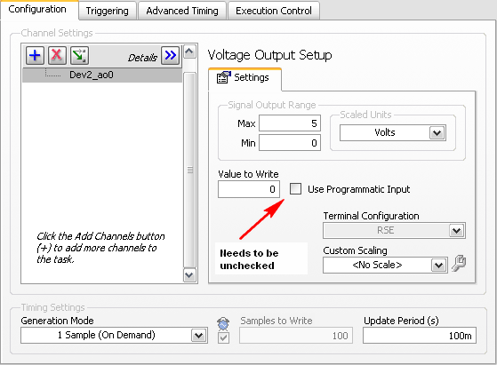
Set the configuration output terminal to the CSR instead of by default.
Five maximum value and the minimum value to zero.
See attachment.
-
Why do I get error 200077 on the SMU-6124 system
My program works well for DAC 6115 and 6110. Now, I'll apply to SMU-6124 (BNC-2110 borad). When I change the mode of DC to AC coupling, error: 200077

 property Node DAQmx channel occurred. More in the attachment. Can someone help me solve this problem? Thank you very much.
renwei,
Please use the Forums of NOR. The reason you get this error is that the SMU-6124 only supports the DC coupling. If you look at the specifications of the SMU-6124 has this as "input coupling. SMU-6124 specification. Regarding the 6115 and the 6110 they charge AC and DC coupling, (card PCI-6110) so it seems that your program is trying to address the coupling of the SMU-6124 as AC coupling. As long as you assign the coupling for the DC 6124 you have no problems. I hope this helps.
-
Error rings using codes.txt and error do not allow entries parameter as rings custom error message?
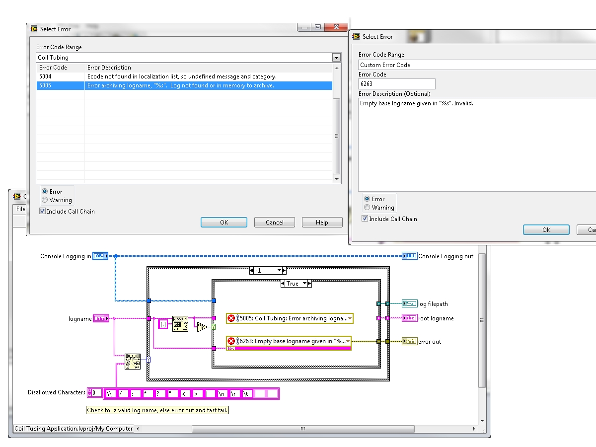
The ring of the error is very useful, especially with its parameterized inputs, you can specific with %s, %f and %d parameters. I would do the same thing in my error codes fixed using the ring of the error so that I can locate them in several languages, but it seems that LabVIEW files text Project never error codes detect or accept parameter entries, you get a ring of the error, but no input parameter. If you use the same string in a client error code, it gives the setting entry but then his hard-coded and you can not locate it. What gives?
Is there another way to configure the rings of error to use a project file for the error codes but still supports parameter entries?
Thank you Esteban but I think you're confusing what I'm asking. The ring of the error is for the treatment of custom error codes. Built in UNITS in the project files error may not take parameters, while that of custom, those who can. See my screenshot.
Maybe you are looking for
-
What seems to be the problem in trying to open mozilla? Or when uninstalling?
I have a problem open mozilla, whenever I try to open it appears "failed to load XPCOM" when I try to uninstall a message appears saying "Installer integrity check has failed.
-
Firefox is to be slower than Internet Explorer since the update. Why?
I upgraded to Firefox, which is my absolute favorite browser and is to be extremely slow. I can't get anything done for what is working on my computer. I am running Chrome. Although this browser is faster than my car, he has few options and is much l
-
Numbers, alignment tools are grayed out
Hi can help with what I expected a ridiculously easy question but I'm a newbie on the MAC world Use numbers 3.6.1 on OS X El Capitan 10.11.2, I 2 of vertically merged cells and now I would like the text to appear middle Center, but all options are gr
-
Pavilion 15: Problem of function keys.
Hello I have a little problem with my function keys. Apparently, I can use them without pressing the "Fn" key on my keyboard. It's really annoying because I have other uses for these keys F1 - F12 and modification of custody whenever I try to use the
-
My canon iP4300 not work on64 bit XP said ' print spooler does not.
I recently changed my computer until I ran a system of 32-bit xp and now Iam updated to xp 64 bit system and my previously fine printer will not work. The message arrives:-"print spooler does not" ideas?