DAQCard-6036E - meter channels synchronization
Hello
We have three devices we want to synchronize:
-' pressure' gives us an analog input
-"valve" needs a square via channel 0 counter wave pulse
-' cam trigger' needs a series of pulses of square via channel 1 meter wave
It works as long as it is the regulator OR the shutter of the camera is attached to the pressure. But when we are together, we get error 50103: resource is reserved. Does this mean I can't use two meter channels at the same time? At least that's what I guessed read other messages in this forum... Or sync not working correctly?
Someone has any idea how to solve this problem, or what alternatives are to use the channel to counter?
Thank you for your help.
Andrea
Hello Andrea,
Thanks for the photos.
I did some research on the synchronization of the two outputs of the meter. Unfortunately the DAQCard-6036E does not support to synchronize the 2 exits of meter
Therefore, you got the error.
The reason is technology OR TIO, who only is not supported for cards E-Series.
Click on the following link:
Material Start Trigger counter for counter sync
http://digital.NI.com/public.nsf/allkb/9C657EE63C9D07A686256F6D0062AC66?OpenDocument
There would be an option if you have a cards M or X-Series with an ARM-Trigger
Synchronize two tasks of meter output using a task HAVE dummy
https://decibel.NI.com/content/docs/doc-11755
Kind regards
Rupert Donauer
Tags: NI Hardware
Similar Questions
-
How to set the output meter channel to generate a signal pulse using DAQ6008
Hello there I am generating a pulse signal of 100 Hz and a duty of 20% of the 6008 data acquisition cycle using visual studio 2013. I have code that needs to generate this but I'm not sure on how to set the channel output meter. When I run this NI MMAX and my vb error code indicates that the physical channel is not supported. I am a user of data acquisition were first and would appreciate any help offered.
If you look at the USB-6008/6009 User Guide and specifications, you will see that the counter in these devices cannot rely as edges of entry. It cannot generate a pulse.
Lynn
-
Crosstalk channel PFI, error Code:-201314
Hello world
I would like to make several synchronized outer edge count the spots on a NI PCIe-6353.
The problem is that I get crosstalk of impulses between the channels of the PFI, leading to some sample clock pulses and possibly error-201314 misinterpreted:
"Multiple sampling clock pulses have been detected in a period of the input signal. Use a sample clock rate that is slower than the input signal. If you use an external sample clock, ensure that this clock signal is specifications voltage level and jitter and seedless. »
I count the pulses of the APDs, they have a height of 5 v, width 20ns and a rate of about 1 MHz. My sync Signal has a frequency of 10 kHz repetition, the pulses are 5V high and long 50µs. When I start the measure, it takes only a few seconds until the mentioned error is displayed. I can also confirm it with the NOT-MAX, in "cash" pulses in my sample clock input channel even if there is nothing in annex (only the DPA on the meter channel).
I tried the following combinations:
connected to sample clock: 0, 5 PFI, PFI 1 PFI
counter connected to: PFI0, 5 PFI PFI 8, PFI 3
they all failed except when I use the PFI8 as the only source of meter.
In addition, the edges of pulse with a lowpass filter of depreciation or the addition of a resistance of 50 Ohms for the connector does not work.
The connecting cable to the junction box is 0.5 m long. I tried the SCB-68 has and a BNC-2110 case without much change in behavior.
Is there a way to better isolate the PFI channels, or are there channels which are better insulated from each other?
Thanks for the help
Fabian
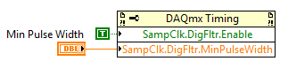
You can set up a digital filter on the sample line PFI clock to prevent noise to register as legitimate a sample synchronization signal (pulse Min set to something less than the width of sample clock but greater than the width of the pulse noise - 5.12 we we use built-in dividers and would probably be appropriate).
If you want to troubleshoot the source of the noise itself, I would start with the scope of the sample clock line (the scope must be fast enough to pick up the pulses of 20 ~ ns if it is indeed the source of the noise). I guess that the problem is more likely to how signals are connected/set to land. Do not forget that the PFI lines on the DAQ card share a digital ground.
Best regards
-
Support for triggers in PCI-6602 for counter input / output meter opearions
I'm sorry, it took a lot of time to test my application in a real NI PCI-6602 map. I am now convinced that put off against channels support start trigger, arms and relaxing break start trigger. But the input meter channels use pause trigger and trigger start of arms only.
I designed the app so that counter 0 is used as a channel of the meter and meter 1 serves as an output of the meter channel. The two channels are configured to use triggers to start of arms. Arms start triggers should come from a line of the RTSI. Using the terminal line 0 RTSI route connect API to arm the trigger for the start of the two channels. So when a pulse comes to line 0 in the RTSI two counter starts counting.
One last thing, I'd like to know, is how RTSI signals are generated? I know that RTSI is used for synchronization of several cards of NOR.
If there is only Board can we use the signal of the RTSI?
Can the hardware PCI 6602 itself generates all signals to the RTSI lines?
Thanks in advance.
Johnson
-
How constantly sample meter signal for quadrature linear encoder
Hi all
Trying to permanently change value of Schneeberger linear encoder quadrature at certain frequency as 10 Hz of the sample and the output to the text file. Everything I choose in the external clock that I can't run the DAQ assistant. No one knows how to fix? I don't know what kind of clock can be used.
I have read a few replies that ppl would connect to an another sample clock in parallel with the meter channel. But I don't know what is the principle of operation of this method.
I spent already as 10hours on it. Could someone tell me that some information?
Looking forwad to your help! Thank you very much!
Best regards
George
Hi George,.
You'll want to use the DAQmx API rather than the DAQ Assistant.
The task of the encoder itself would look like this. You need not use the trigger options.
The problem is that you will need to generate a clock from another source that the card is unable to generate examples of clock counter directly. The simplest is probably to use the second counter. Here is an example showing how to use a meter to output as a sample clock (although the example shows the analog inputs, simply replace the task of analog input with the task of the encoder shown in the previous example, I linked).
So, you would use a counter (say ctr0) for the task of the encoder, and then the other (ctr1) meter for the generation of sample clock. You must specify your task of encoder using the InternalOutput of ctr1 as the sample clock (if the internal counter output appear in the drop-down menu, click with the right button on the terminal and select the e/s name filtering > include Advanced terminals). Start the encoder task before the output task (although given that both are running continuous it doesn't really matter that much).
In addition, 10 Hz is not too fast. If the exact date is not as important and the above seems a little overwhelming, it might be easier for you to just run a loop of 100ms clocked by the software from example like this. Note that the exact time loop pourrait will vary from cycle to cycle, so this method is not very good if you use sampled data to perform calculations of rates.
Best regards
-
create file csv with multiple channels
I am writing a program that uses the Keithley 705 scaner and 580 ohms meter. What I have to do is to create an excel file that contains a timestamp to MM/DD/YYYY HH: mm
 S as a column, then a new column for each channel (1 to 10 in the case of the keithley 705). Each channel column will contain reading the resistance of this specific at the parking meter channel. The timastamp should do when the first analysis was performed; for example if one scans the channels 1 and 2, their resistance values will be associated with the same timestamp.
My question is how can I format it as an excel file.
Answer your original query
Set the number of channels (1-10)
Organize your table value to it form the first column with timestamp and treatment of channel values, then write in the chain of worksheet
You can include the header for your nominale1 -
Audio channel cutting and reissue of links?
People of Hy,
last week I got an annoying problem, or maybe I didn't know how this function works, or if it is still possible.
I am a convinced user first CS6, but some features are better in Final Cut - sorry I have to admit.
Why?
Last week I had a first CS6 project to finish (it was already edited 90%). I recognized this sequence got 1 Audio track with L and R channel and just the R channel was helpful (the L has been trash).
I just couldn't not to throw the channel L. I had to go back to the project window, edit clips, place the R channel in the stereo channel, synchronize all audio tracks manually and then replace the stereo track by the R channel. It worked, but I had to the wast time to correct this. There may be a simpler solution in my opinion.I first tried in the timeline to disable the L channel, and that (as in the final cut) by pushing a slider on the side R in the center of the channel mono-R is symmetric left and right all also that he had no such cursor. Something like this would be a great improvement in the future and save time if you set up a project in a way that is not useful .
My question is: Y at - it an easy way (I don't know yet) to split a stereo 2-channel mono in the timeline? Alternatively, I can balance the right channel or left after cutting a single channel (if the output is not only on one side)?
Another question: after synchronization MANUALLY audio clips even once, I was wondering if there is a function where I can create a link to an audio clip (the same or in this case, the clip of momo (coming from the same AV clip)) for the video after you remove it?
Because sometimes, you delete an audio clip (from an AV file) and later you acknowledge that this was a mistake - and you don't have to points on the source file, so you can just crash clips? A feature like a right-click on the video and the audio file of the restoration of this video clip, and if you have a L/D montage, for example, a window opens and ask you if you want to fill empty space audio track (J/L edit stay) intact or crush it and the video and audio clip have the same length?Is there a function something like that I don't know?
Because sometimes you're working on a project with several people and they do something that makes life harder or a director/producer change I don't mind that I face every day?
Thanks in advance for help and clarify!
BR
There may be a simpler solution in my opinion.
There are. Just add a level of track fill right effect in the mixer. Maybe five seconds worth of work (if you're lazy about it).
a function where I can recreate a link to a clip for the video clip after you remove it?
Framework to match the video. Opens the clip in the Source monitor with set In/Out points. From there you can simply drag down audio and connect it to the video.
-
DAQmx tasks for Subvi of good practices
Hello
I wonder about the best way to create the subVIs that don't repeatitive entry analog and digital output several times in a program. Specifically, should I create a new task using DAQmx create channel in the Subvi or should I create the task in the main VI and put the task in the subVIs? Create and delete a new string into a Subvi would affect the States of digital output line (for example to change a line in the default state) after that the program will stop at the Subvi?
I'll collect digital 6-channel analog inputs and 2 outputs to control a magnet. The program only collects analog inputs for 5 seconds each time (based on the user's selection) and active the magent or not based on the analog input.
I update an old program LV traditional data acquisition functions allowing to use the new DAQmx features. The old program was written in LV 8.6 and used the DAQCard-6036E card and I update it LV 2013 and the USB-6212 mass unit.
Thank you
Frank
If you call this VI a good amount, then I create the task in advance and pass it in. Re-create the task just request in trouble, especially since I don't see you close either.
-
How to use an internal counter of the cDAQ-9172 for measure PWM and generate the frequency?
Hello
Requirement of my project is to measure 6-channel PWM and generate 5 frequency channels.
Suggestion of engineer OR bought cDAQ-9172 chassis and NI 9423 (8 DI correlated) and NI 9474 (8 correlated DO) for this requirement. I have a few questions
Article:
1 > what should I know to customize my CompactDaq 9172 chassis
http://zone.NI.com/DevZone/CDA/tut/p/ID/9367
I know that this way to synchronize the physical support 32 correlation system pin o for housing 1-4.
=> I'm not really sure how to use these channels synchronization support.
2 > using internal counters on one NOR cDAQ-9172 as a sample for other tasks clock
http://digital.NI.com/public.nsf/allkb/ADFC4DD8C9690232862575B70079FBD4
I know that I can change the ownership of the physical channel so I can get 2 meter outside the frame 6 and 7.
=> I do not think that this solution will be me because I can use only 2 counters with this method.
Could someone tell me please how to fix my project requirement? How to choose the setting for DAQmx screws?
I have experience with measure the PWM and generate the frequency, but with separated against only.
Best regards
Thang Nguyen
Hey Thang.
AHA... for this, you can use the channel property node.
See you soon
Lab
-
Error for counter - write frequency
I get the following error in Labview trying to write property of the duty of a meter lifecycle:
Error - 200301 occurred to DAQmx Write (counter frequency 1Chan 1Samp) .vi:1
Possible reasons:
Measurements: Unable to update the generation of pulses property.
The generation of pulses with previous property settings must complete a full cycle before the property can be updated.
The code consists of a loop running every 100 milliseconds, which adjusts the operating via a property node factor, and then performs a DaqmxWrite on the same channel to force the new property settings to take effect.
There is an initialization step before the loop where the meter channel is created, synchronization is set to continuous and the task to begin, followed by a 500 MS delay (I thought maybe initialization has not been completed before the writing of the 1st loop).
There are actually 2 separate channels / counters in the loop, each with their own task.
Generally, the code works fine. Sometimes, when I download the new code to the machine, this error occurs.
Any ideas?
Thank you
Kevin T.
Hey Kevin,
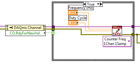
The error you get is expected in the way that you program your application. For another way to implement the property node and to avoid the error, please see the Developer Zone program example: output frequency of meter to change on the fly.
In this example, you will find this implementation:
I recommend you put it in your code and see if it is able to resolve the error you see.
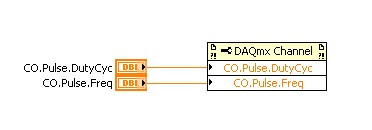
In your program, as useless the DAQmx property and DAQmx writing during the definition of the duty cycle and frequency. You must just writing DAQmx to set these attributes.
Also, as a note, I noticed in your code that you never clear the task. Don't forget to end the application with a Task.vi claire DAQmx. I saw one in your program.
-
SCXI and acquisition with Windows 7 x 64
Our just updated IT to update our phones and we have received Windows 7 x 64.
Data acquisition, we use the SCXI hardware in the SCXI-1000DC chassis and an acquisition of data SCXI-1600 USB card. Doing my gear OR set up on the new laptop, I discovered that neither does not support Windows 7 x 64 for the SCXI-1600. The other options to connect the SCXI-1000 chassis to a laptop are the DAQcard-6062E and DAQcard-6036E, nor which supports Windows 7 x 64. According to the information below, there are no plans to support x 64.
What are my options to continue the use of the material, we have invested with the laptop running Windows 7 x 64?
You will need the NI SCXI-1349 connection block and SH68-68-EP cable. The SCXI-1349 plug at the rear of your SCXI module and cable connects the 1349 the USB device series M mass termination. The rest of the configuration is identical to any PCI/PXI E Series device. The USB M Series device will be the analog-to-digital converter for the system instead of the SCXI-1600.
-
SCXI and USB 6210? Getting started...
Hello
I'm looking to get an online data collection system and had a few quick questions of SCXI signal conditioning high-performance... First of all I have is 1 chassis SCXI-1000, SCXI-1121, SCXI 1180 and 1100 SCXI modules assorted. I also have a few blocks of different endings, SCXI-1300 block and a 1320.
(1) by section "what to start' in"the SCXI chassis user manual"everything only I need is hardware of SCXI chassis (in my case the SCXI-1000 chassis), a 120 VAC power chord and a computer. However in the ' what you need to get started section "of the manual"Getting started with the SCXI"I need also a SCXI-1200 or"Hardware DAQ"module So my question is this, can I set the SCXI-1000 chassis directly to my laptop without any additional hardware? I feel, I need something else, but want to make sure...
1 (b) assuming I need a material additional DAQ to start, I can use a NI USB 6210 somehow? I checked the manuals and little is said about SCXI.
(2) neither manual mentions a controller, but the SCXI Advisor shoot one. They should say if all I do is collect data, not active control?
Thank you
Mike
Mike,
There are two options for you to get your SCXI system operational. You will need either an M series or a card of E-Series you connect to your SCXI system or you could focus on the NI SCXI-1600, which is a controller for your SCXI chassis and allows you to connect your laptop to the controller via a USB cable. This controller will operate similar to the E-Series and M-series cards.
We also offer a couple of PCMCIA cards which allows you to integrate the SCXI system with your laptop. It comes from the NI DAQCard-6036E, and NI DAQCard-6062E. Unfortunately, your NI USB-6210 is unable to be used as a device for the Acquisition of data for your SCXI chassis. The list DAQ cards which are possible to use with your system can be found here on the tab 'controller '.
http://ohm.NI.com/advisors/SCXI/pages/SCXI/modules.XHTML?conversationContext=1
In addition, we have an old manual SCXI of starting you can find here:
http://digital.NI.com/manuals.nsf/WebSearch/C195895E8C9CAE3D8625691F004DB285
-
Pulse/counter of encoder data wrong servo motor
First of all, I am very new to the use of labview. I'm trying to complete a project, a former employee was working on that.
For a quick background on what I'm working with, I use an NI DAQCard-6036E connected to a SC-2345. SC-2345 is then connected to a load cell, Omron R88D servo driver and an omron servo motor. The actuator is an incremental encoder with resolution of about 2048 pulses per revolution. My labview program includes a counter that records the data of the encoder on the servo-motor. I was able to get accurate data during the test through the program of measurement and automation of the engine manually. Also when running through the specific DAQ assistant, I use for my counter, I'm getting correct readings by turning manually engine. Once I run my full program, instead of get 2048 pulses per turn, I'm between 34000 and 36000 pulses per revolution. The more logical assumption is that I get vibrations in the engine itself or some kind of noise disturbs my signal. First, I tried to change the possible settings via the omron servo driver that could reduce the vibrations of the engine. I try to change the stiffness settings, enable, and disable the automatic adjustment feature and a few other parameters specified by the user manual which could cause vibrations. If turn the settings from rigidity as low as possible, I am able to get around 2000 impulses per turn, but data are very sporadic. In addition, my equipment must be very stiff, and with setting the lower rigidity for the servo driver, I can almost stop the engine with a minimum of force. My equipment must be able to travel at a near constant speed with fluctuations of up to 200 N force. Any suggestions on the direction in which I should go in search of a countermeasure?
Thank you
Experience with actuators is that they can produce large quantities of electrical noise. I guess that noise can enter the signal of coders. Look carefully at your wiring and make sure that you do not have a ground loop between your hardware OR and the actuator.
-
Greetings,
Just got a new computer @ work & it's not a PCMCIA slot. I do a lot of development using 6036 series cards, PCI and PCMCIA. Did anyone tried a USB to PCMCIA with the DAQCard-6036E multi i/o?
Speaking of something similar to this... http://www.elandigitalsystems.com/USB/U111.php
Thanks in advance,
Rob
Hello Rob,
Here's another thread that relates to your question.
Kind regards
Jeff L.
-
Shunt calibration factors expected
I'm trying to shunt calibrate a rectangular rosette extensometer attached to a module CSC-SG01 (using a SCC-SG11). I use a SC-2345 connected to a laptop with a card DAQCard-6036E. I read in an analog voltage with the SG11 engaged and subtracting the value w/o it committed. The expected value of Vexpected = (R3 * Vex *(Rshunt+R4)) / (*(Rshunt+R4), R4 + Rshunt + R3) is then divided by the difference to get the correction factor. For the Vprevu, R3 = correct R4? I get a value of less than 1 correction factor (~. 97), which for me has no meaning, as shunt calibration is supposed to correct for the resistance of the wire. I understand that although the correction factor must be > 1?
Thanks in advance for your help
Hi William,.
If we look at what happens internally in the SCC-SG11 in looking pg 17-18 in the Manual, it shows a diagram and an equation for the sample. Set all values of 120 to calculate your measure expected and then it varies from 119 to 121 and divide by the expected value. If the resistance is greater than 120, you will get a lower measured voltage and a ratio of > 1. If the resistance is less than 120, you will get a higher voltage that is measured and a ratio of<>
Maybe you are looking for
-
Academic journals, leading to the shutdown of Wifi
It is a problem of confusion I have known during the last two weeks. When I tried to connect to the following sites (http://journals.cambridge.org/action/displayAbstract?fromPage=online & aid = 210139 & S0269915X03002039 = starts and http://journals.
-
Update firefox on an eeepc900a
The update is grey on my EeePC 900a. The existing version is 3.0.4Is there no way to update for this PC?
-
Re: Windows 7 on Satellite Pro C50-A-1HQ
I have a Satellite Pro C50-A-1HQ with windows 8.1 and I'm pretty tired of this OS because of problems with the use of disc 100% that I get sometimes and I have not been able to solve. I would like to install windows 7 in this labtop. Do you know if t
-
Camileo H30: I can't open .avi using Pinnacle studio 14
Nice day I can't open .avi in my studio from Pinnacle 14 of my Camileo H30 Where is the problem and how resolution? Camileo H30, PC with Win7. Thank you. concerning/MH/
-
Error on MacBook with boot camp disc
Hi, I was werking with Autodesk AIP2012 and tried to export a file as PDF wen I got to "clerical error" and inventor stopped and half THE icons on THE desktop was gone. I restarted the computer, but Windows won't start. I have the OS startend and tri