Shunt calibration factors expected
I'm trying to shunt calibrate a rectangular rosette extensometer attached to a module CSC-SG01 (using a SCC-SG11). I use a SC-2345 connected to a laptop with a card DAQCard-6036E. I read in an analog voltage with the SG11 engaged and subtracting the value w/o it committed. The expected value of Vexpected = (R3 * Vex *(Rshunt+R4)) / (*(Rshunt+R4), R4 + Rshunt + R3) is then divided by the difference to get the correction factor. For the Vprevu, R3 = correct R4? I get a value of less than 1 correction factor (~. 97), which for me has no meaning, as shunt calibration is supposed to correct for the resistance of the wire. I understand that although the correction factor must be > 1?
Thanks in advance for your help
Hi William,.
If we look at what happens internally in the SCC-SG11 in looking pg 17-18 in the Manual, it shows a diagram and an equation for the sample. Set all values of 120 to calculate your measure expected and then it varies from 119 to 121 and divide by the expected value. If the resistance is greater than 120, you will get a lower measured voltage and a ratio of > 1. If the resistance is less than 120, you will get a higher voltage that is measured and a ratio of<>
Tags: NI Hardware
Similar Questions
-
need to know if the NI 9237 - no compenstation such temperature on bridges and shunt calibration
need to know if the NI 9237 - no compenstation such temperature on bridges, also, I need to know if she calibration shunt.
Hey invzbl_rkl,
The NI 9237 - can do both remote sensing and Shunt calibration. You can see the details on how to connect the bridge in the USB-9237 user guide and more details about compensation in the article attached Developer Zone on measurement of strain.
Specifications and NI USB-9237 User Guide
http://digital.NI.com/manuals.nsf/WebSearch/B218E7E6DDB1D4518625738600784930Strain with gauges
http://zone.NI.com/DevZone/CDA/tut/p/ID/3642 -
I'm trying to calibrate the NI 9237 + NOR 9945 quarter bridge extensometer or max.
I get the error-200077 occurs calibration of strain meters.
Possible reasons:
Requested value is not supported for property value,
Property HAVE. Min
Asked the value - 1.0E - 3
Valid values begin wih 18.8988984e - 6
Valid values ending with 103.843984e - 3
Channel name: strain
I've tried everything, the meter of different strain, different 9945 9237 different, different cables, different computers. everything.
I changed all the settings I found in or max.
I searched the forums and inernet and what is there is not help.
Any ideas? Please? I'm so desperate.
I just got the same error message again and again.
What went down: when I set my limit min between the highest and lowest allowable values specified in the error and then dialog window have been, I had the same mistake all over again, but the highest values and more allowed bass displayed in the window had changed to completely different numbers. This happened several times. No matter what I put my limits, allowed values min max always change, so it would be mistake every time regardless of what I entered. Sometimes he complain on the gain of shunt calibration factor, he couldn't put it is '+ inf' or '-inf '. Looking closely at the calibration window, I noticed that NEITHER MAX read the same value of strain, with or without, the resistance of the shunt connected. When the calibraion subtracted Y2 - Y1, he got zero, and the opposite of zero is started. This is when I knew for sure it was something my son and began the search in there deeper.
Cause: short in the wires running to the extensometer. When the specimen has been assembled and bolted on the luminaire, the wires were hidden so that nobody could see them, and they were crushed between two metal components.
Solution: look for shorts or other problems in the wiring itself extensometer. I imagine that if the strain gage circuit is open, you would see probably the same error of MAX NOR in this case as well.
Recommendation: I ask OR to add more useful information in the dialog box for error, to offer the user to check the wiring, etc.
-
Calibration shunt 9235 with 9144 in Scan Mode
Hey everybody,
I use two 9144 s and a 9074 and I am trying to create a routine calibration of shunt for 12 9235 s (4 per chassis). I found this article on how to shunt calibration with the 9144 and a 9237, but it does not work:
http://digital.NI.com/public.nsf/allkb/12017868777480AE862579BA004F0877
This is the error I get:
Error 65723 appeared to node (arg 1) property in the Shunt Cal 9235's.vi
Possible reasons:
CompactRIO: This module cannot be configured when the engine of the controller is in its current mode.The thing I don't understand is that the modules on the 9074 calibrate correctly, but when I try to calibrate a channel on one of the 9144 s, I get this error. I couldn't find much about this error, I was wondering if someone could help me and point me in the right direction.
I have attached my code. It is relatively simple, and I don't see where the problem would be. I have to manually set the mode of the 9144 something than what it is currently (i.e. Active configuration)?
Thank you for your help,
Seth
Your system may start in Active mode by default. This mode does not allow to set the properties of your ECAT 9144 chassis. the chassis must be in configuration mode to enable the derivation property. See attached changed VI.
DirkW
-
calibration of strain using Signal Express measurers
Hello
The first time asked. Thanks in advance.
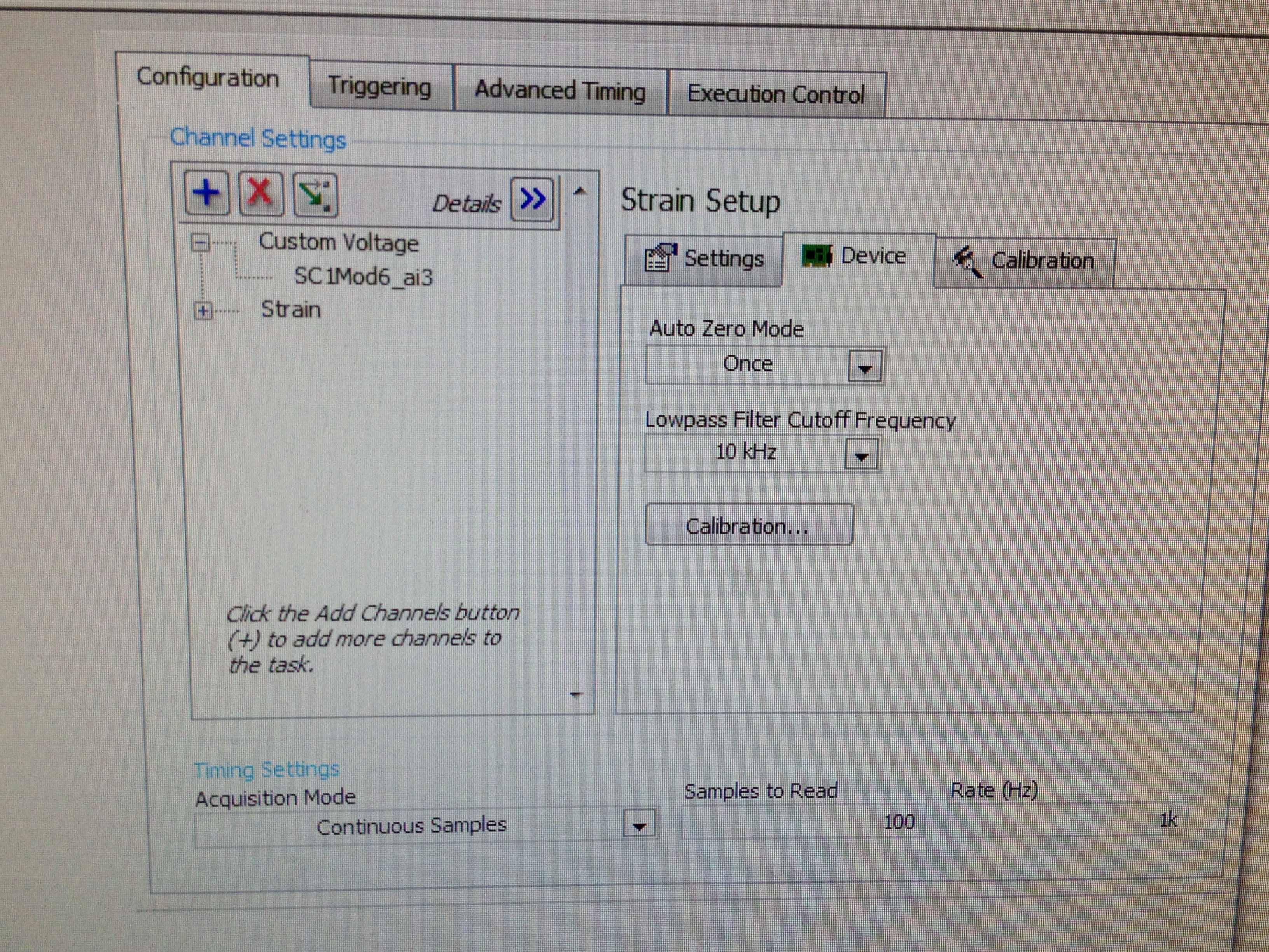
I use NI DA system to record the strain of a strain gauge 1/4 350 odm. The connection string would be extensometer---> SCXI-1314 (Terminal)---> SCI 1520 (block 2). I connected the cable to the S - P + and PIN the SCI QTR 1314. The value of the strain appear in LABVIEW EXPRESS. Now, I need to calibrate the extensometer (OFFSET REMOVAL and CALIBRATION of SHUNT). I'm stuck... I have two specific questions:
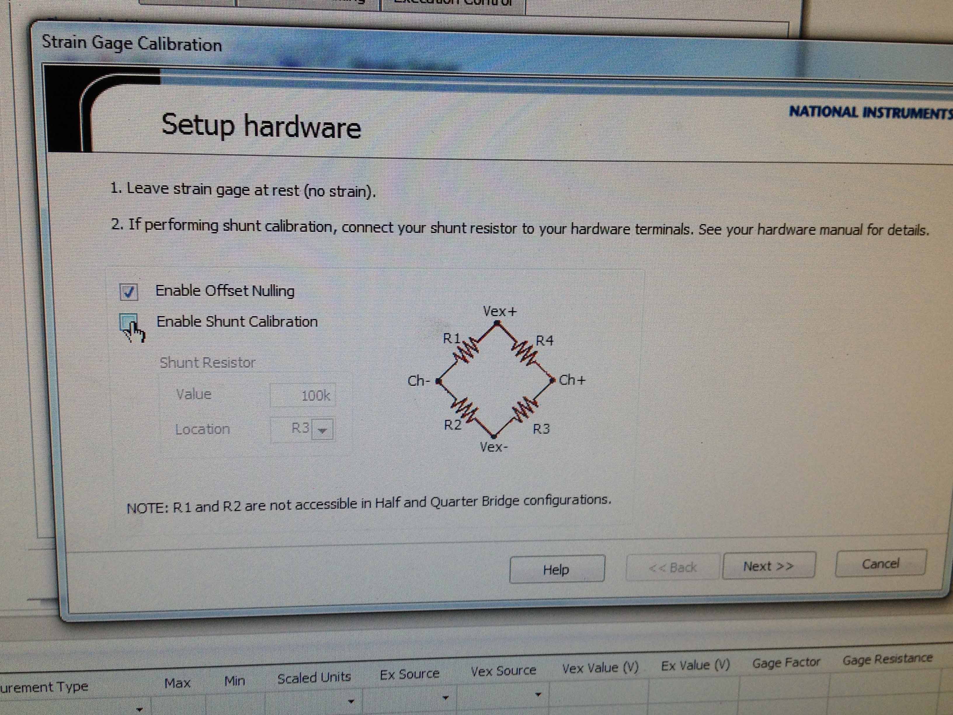
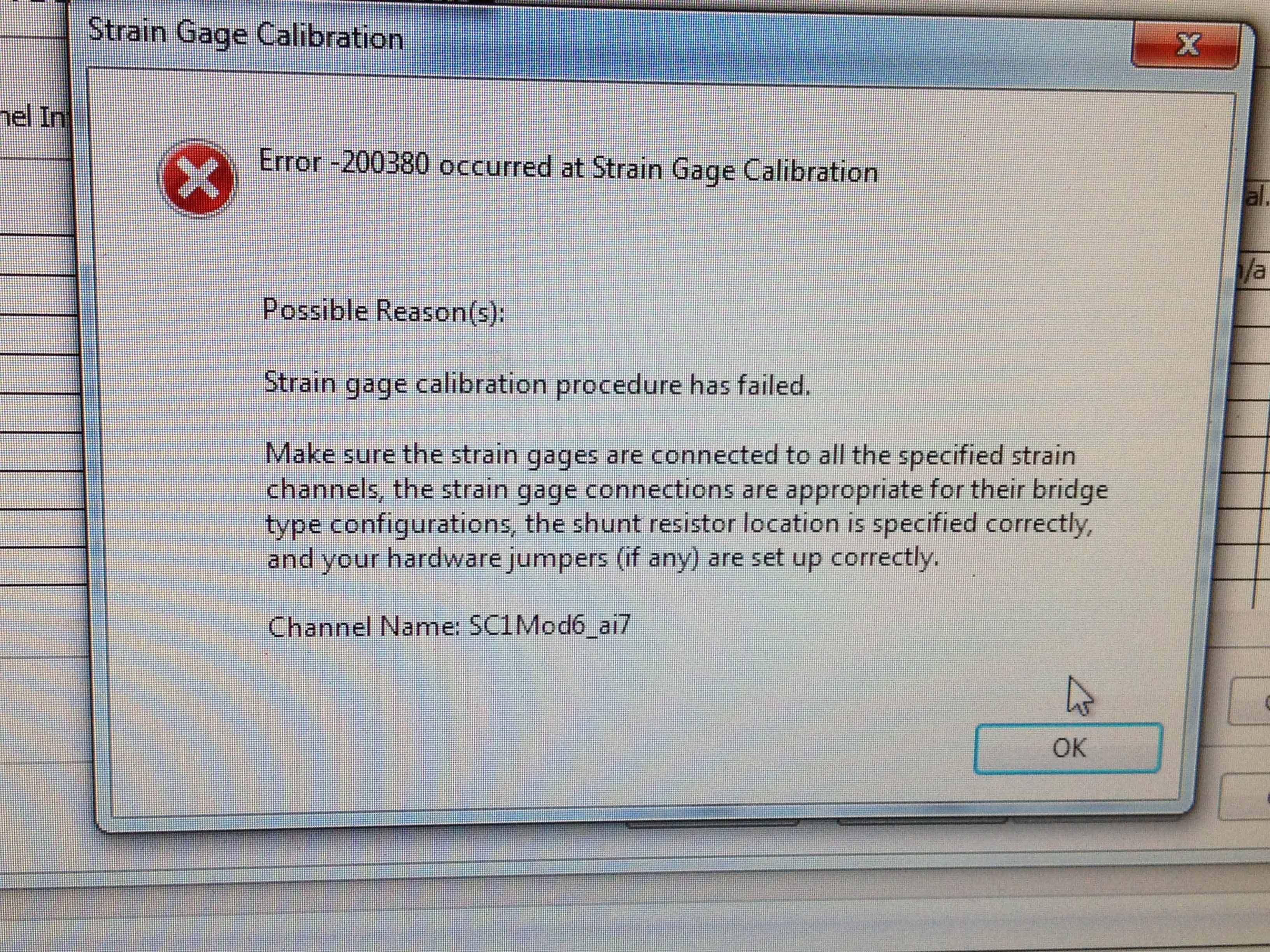
1. when I just check 'Offset the removal' in 'calibration' tab error-200380 orrcurs. Can you guys help out me?
2. I noticed that there are specific pins for the SCXI-1314 shunt calibration. If I wanted to shunt calibration, must I change my wiring, so that the resistance of odm 100 k can be included in the circuit?
Thank you very much.
In your first post, you have the cable signal since the pledge is going to S- My first suggestion is to move your thread to signal S - s + if you don't have it already done. When 1/4 hanging bridge you only have access to R3 and R4 which are on the + next to the bridge. This high an error on your gain stage is usually a wiring problem or you maneuver the arm hurt in the bridge. In the calibration Assistant spend R4 R3 and see what happens.
How connected your pledge?
Of your pledge, you should have 3 wires. Vex + (red) on a tab of the pledge and shunt cal and GIS (tied together) on the other tab of the gauge. See my attachment to a vision of how I wired my system. Other colors, the screenshot of your wiring diagram looks like it should work. The difference being, ma sig + is green and the shunt is brown; where your of seems to be white and black. Anyway, double check your pledge and make sure that leads back to your terminal block are where they should be. In the 1314 default shunt resistors are all 100 kilohms unless something has changed in your system, you should be fine.
You can attach a copy of the file .seproj or tab 'Settings' from your screenshot strain gage configuration window. Things like factor value excitement and resistance will affect your calibration and output.
-
Calibration with NI9237 and NI9944 strain gauge.
Gentlemen.
I have a cDAQ9172 OR with NI9237 and the bridge 1/4 NI 9944. Practically, I'm working on measures of strain gauge issues using a strain than 120 ohms connected to the NI9944 to build the bridge half happening inside of 9237. I have a continuous doubt how is the calibration for the strain gauges. The manual speaks of a shunt resistance which, in the case of NI9944, is already in the system. The manual says that I don't have the shunt resistance external nee. It is clear.
My question is this:
the menu for calibration requires a resistance value that I don't know, I'm leaving in the value proposed by the menu of NOR. The strain gauges takes easily compensate, so I always have to recalibrate the channels in the NI9237. Is this normal? Can a (application to 2.0 V strain gage) voltage of 2.5 [V] generates a continuous drift of the measure?
Strain gauges are: EA-06-125BT-120
Hi cgenco,
Because the NOR-9237 with 9944 uses an internal resistance for shunt calibration, you need not to worry about the value of the shunt resistance. Take a look at the following article that specifies how connections are made. Calibration article will show you the basics behind how to exploit.
Also, since there is a ratiometric measurement, the voltage is 2.5V shouldn't matter as long as your pawn takes care of everything.
-
Access 9236 shunt cal with scanning mode?
How allow us calibration shunt with scanning on the module 9236 quarter bridge strain gasoline
We are very happy with the release of Labview 2009 and RIO 3.2 because most of the cRIO modules now supported the scan mode.
We want to use the interface in scan mode with the quarter bridge strain Guage 9236 module, but we must be able to access the features of Shunt calibration. With the FPGA interface, you acquire a set of data. Then allow you the shunt calibration and gain a second set of data. Then you compare the two to get to a scalar value using some equations. This eliminates lead resistance in your calculations, which can be less than ignorable in certain circumstances.
Thank you
It was easy. I just hung out and left down the constant IO then right mouse clicked on it and all its I/O write properties come. Very cool. All too easy to be crio programming, lol.
-
"Bridge shun cal.vi" shunted the setting of the value?
I copied the "bridge shun cal.vi" LabView example "Acq gauges bridge samples (with calibration) .vi", to include in a strain measuring .vi I'm working.
My equipment consists of an SCXI-1001 chassis, modules of 1520 and 1314.
That means the acronym for setting the value of "Shunted"? Resistance value of triage (in ohms, I supouse)?
And it's less important to me, but think it may be interesting for others: how to choose between the calibration shunt resistance is or B?
Thank you
usuario
Hi user,.
You are right when you say 'shunt resistance' in VI stands "DAQmx perform Shunt calibration (bridge)" for the value of shunt in ohm resistance. As you can see on page 4 of the SCXI-1314 manual, the two shunt calibration resistors A and B are have a value of 100 kohm. In addition, page 4-28 the SCXI-1520 user manual specifies that they are are in style RN-55 (standard 1/4 W).
Choosing to respect so shunt calibration resistance A or B, the latter manual mentions on page 3-4 that "shunt calibration switches A and B are parameters of control of software that allow or activate or deactivate the shunt calibration resistors in order to form win calibration." In most cases, you do not explicitly switches shunt calibration check, he makes instead of software driver to automatically adjust them for you during the shunt calibration procedure automated. However, if you want to explicitly control the witches of calibration, you can write an application program which controls the shunt calibration switches.' and returns the user to Chapter 4, principle of operation, for more information.
I hope this helps.
Kind regards
-
Straing gauges - calibration for measurements
Hello
At first, I'm sorry for my English, I'm Polish and I do what I can

I t prepare strain measure simple application on cylindrical tube. Has created this task to MAX and now I have a problem during calibration. Performed shunt calibration.
The main idea of my program:
After clicking on "run" arrow in the upper-left, I will send to the tab named "calibration"(default tab) (it can also be cluster tab instead, is not serious). "." Then I load sample tested with, for ex. 1000N and the program of calculate the coefficient between the force (1000N) and the real value of NOR-9237 (configured as analog input - bridge to the MAX). Then I move to the next tab, described as '' measure '' when I perform a simple measurement with strain vs.time graph.
I have established that the dependence is linear, so I have to use y = ax + b formula. Assuming that 'b' 0, I have to find 'a' - how can I calculate and how can I keep it for use in the next tab, 'measure '? I have no idea...
I attach no examples of my program, because there is nothing difficult yet - DAQ Assistant and graphic waveform...
DAQmx provides a way to create "Ladders", but also "Tasks" a linear scale is easy to assign to a channel in a task.
I'm in the middle of an upgrade from LabVIEW today so, Kudos to anyone who publishes the screenshots I can't get right now.
-
Negative results with strain gauges
When I run my VI the results are always negative. I use the NI9237 with the NI9945. I wired my installation as one quarter bridge. There are three wires from the strain gauge. I went on the wires and I think it's okay / characteristics of NEITHER. Is there something in the MAX that I should be looking. Not sure why the values are negative.
Thank you
Harry Stone
Hi Harry,.
There are a few things I want to clarify:
-Traction deformation is positive and compression deformation is negative, what is described a high level in the tutorial below.
Strain with gauges
http://zone.NI.com/DevZone/CDA/tut/p/ID/3642As strain compression is negative, you would see negative within MAX results if your strain gauge knows any compression. Please keep in mind that a shift can be associated with each transducer, that's why some sensors use a calibration certificate. It is produced by the manufacturer and is provided with the sensor as is the specific sensor. The sensor goes through a testing process to determine its actual response compared to the ideal. In this case, a scale of table can be created to include these values.
How to do a custom able scale & Automation Explorer (MAX)?
http://digital.NI.com/public.nsf/allkb/3F6558112FD2C776862575B5004F7F87?OpenDocumentNot all manufacturers of sensors provide a calibration certificate. Or you can create your own table by placing known quantities of pressure, force, etc. on the sensor and map it to the corresponding voltage, or you can create a linear scale in MAX adjusting the intercept (b) the value necessary to remove any compensation.
You use the NI 9237 that compensated supports deletion. A null offset is executed with the sensor fixed without load placed on the sensor. Actually, a measurement of voltage is taken and this value is subtracted off the coast of each subsequent measure therefore removing the start offset. This takes up space you creating a linear scale and in doing so manually.
The two links below show how to use a custom scale created in MAX in LabVIEW, as well as coding the custom in LabVIEW scale to remove the dependency of MAX.
Acquisition of DAQmx with custom scale
http://decibel.NI.com/content/docs/doc-3706Create a linear scale customized for each channel AI in LabVIEW using DAQmx
http://decibel.NI.com/content/docs/doc-11136I recommend using a task sequence. Input parameters for the information about your strain gauge needed to perform the conversions of strain. There is an example of a measure of deformation in the example Finder LabVIEW (* open LabVIEW * help > find examples) designed specifically for the NI9237 that incorporate deleting the offset and shunt calibration devices. If you do not have external wires connected for calibrating shunt such as cited in this document , you will receive an error. Here is an explanation from the NI-DAQmx help Shunt calibration (start > all programs > National Instruments > NOR-DAQ > NOR-DAQmx help) to help better explain this feature.
Shunt calibration (adjustment of Gain)
You can check the output of a measurement system based on a bridge by comparing the measured output bridge with a calculated value if the physical load on the sensor is known. NOR-DAQmx can then use the difference (if any) between calculated and measured values as a factor of adjustment of gain for each measure. You can simulate the application of a load at the bridge by connecting a significant resistance in parallel with the bridge. This resistance, known as a shunt resistance, compensates for the voltage from zero of the bridge. Because the value of the shunt resistance is known, you can calculate the physical load corresponding to the voltage drop of the resistance.Use the Shunt calibration perform the Assistant DAQ or DAQmx VI/function to perform a calibration shunt, which defines the the gain setting for a virtual channel. NOR-DAQmx then uses this adjustment of gain when you descale readings from the bridge. Some National Instruments products are internal resistance.
This may seem like information overload, but I wanted to provide you with a detailed explanation of your understanding, in addition to immediate responses. As a logbook, I recommend that you use the 9237 strain example and use the removal compensation. Negative values are expected for compression and positive for blood. The handy Guide below gives an excellent overview of the strain gauges, which also includes a video.
Measurements with strain strain gauges: practical Guide
http://zone.NI.com/DevZone/CDA/tut/p/ID/7130Hope this helps!
-
Wavy jagged singal of 9237 at no load condition
Dear forum users and employees of OR,.
I would be grateful to you if you can solve my problem. My specimen is a simple piece of plastic 1 0.25 inch rectangular cross section with a length of 8 inches. I'm trying to measure the deformation (with the help of use general TML, Japan 1 mm gage length extensometer) in the sample by hanging dead in the sample weights. I am able to strain using the cDAQ 9178 chassis, NI 9237 module with accessory NI 9944 quarter bridge. For a given weight (so the applied load becomes a static), signal (output voltage) must remain constant independent of time. In addition, I also expect that when no load is present on the sample, the acquisition system data above should show constant, but the deformation of almost zero output over time. What is my problem only after offset removal and shunt calibrated correctly with the help of the wizard of LABView DAQ, the above data acquisition system shows a strain of output wavy stair of significant variation between maximum and minimum, even when the sample is at no load condition (the sample is simply placed on the table). In addition, even after loading the sample with a certain amount of dead weight, rather than get a constant signal, I always get a strain of output wavy stair (with more scale position zero load) over time. Please help me get a constant output signal for the data acquisition system above with and without load on the sample.
Thanking you
KSRKM
-
Configure a load cell connected to multifunction DAQ
I'm trying to connect a LCDH Omega 10 K scale by a module of constraint Dataforth SCM5B38-37 then AI0 gauge on a USB-6251 multifunction data acquisition.
In addition to the load cell, the application will use a pressure sensor with a strain gauge bridge module plugged into AI1 to read the pressure of hydrulic. The pressure transducer using a measure of the force will be calculated and compared with the reading of load cell.
Currently, the USB-6251 box is configured to read analog voltage on AI0. The scale is then performed using linear Fit.VI.
Review the example Bridge - entry continues shows some additional controls may increase the accuracy of the reading.
Unfortunately trying to use the DAQ Assistant only added to my confusion of the best practice in the acquisition of a signal from a load cell.
__________________________________________________________
Here are some of the questions I have...
What is the best practice implement a load cell using a full bridge strain gauge conditioning module labview?
What is shunt calibration? Is this similar to the USB-9237 DAQ modules-specific?
How do you know if your sensor is set up like a full bridge, half bridge, etc, the document load cell does not it?
You can use the VI delete DAQmx perform bridge?
_________________________________________________________________
I don't know, I understand all the information of the map calibration either.
Why is there resistance to entry and exit values?
What is the value of the zero balance signafiance?
Specifications of load cell
Lbs mV/V
0.000 0
2000 0.598
4000 1,201
6000 1,804
8000 2,404
10000 3.002
Excitement: 10 VDC
Input resistance: 350,41 Ohms
Output resistance: 352,08 Ohms
Balance zero: 0.01 mV/V
Hello!
I was looking into your question and found a few links that might help you configure your system. The first is a white paper that discusses some of the basic concepts of the gauges of constraint and their use with LabVIEW, shunt calibration and also covers some of the resistance values you see:
http://www.NI.com/white-paper/3642/en/
As you can see in this article, we have some specific hardware, built for the kind of measures you take. Because these devices are manufactured specifically for this application, they would provide better and more reliable results. That being said, you can configure your system with your USB-6521, it might not be as accurate as one of these systems. To set up your measurement system, rather than defining the analog input as a measure of deformation, you want to use the voltage custom with the option of excitement. This article treats this yet:
http://digital.NI.com/public.nsf/allkb/C66F92BDE229F45A86257B6D004D6033
We get you your data in the form of Volts/Volts (this document addresses more info on bridge probe scaling: http://zone.ni.com/reference/en-XX/help/370466W-01/measfunds/bridgescaling/), , but you should make sure you standardize this value to the excitement. Devices such as the NI 9237 provide the voltage and can take this known value in to account within the program, but you may need to do this manually for your application. Here is additional information on the NI 9237 and how it is configured to read information from strain gauge:
http://digital.NI.com/public.nsf/allkb/892C84122A6501AE86257547007E5C53?OpenDocument
Regarding the configuration of unit load and the information, you can try to contact the manufacturer for more information!
Thank you!
-
DAQmx create several channels of
I downloaded the program entry OR bridge-continues and tries to modify it slightly to allow several Wheatstone bridges to connect. Currently, it has the ability to connect to a single channel but don't not to acquire information from several channels simultaneously. All information regarding the shunt calibration, bridge information and waveform graphic output remains the same. Ideally, the program displays the greatest value in the final waveform graph, but it is fine if it shows separate graphs for each of the two entrances. I was playing with it without much luck though if I start from scratch and you use the DAQ assistant, I'm able to get information without penalty. Any help would be appreciated.
In fact you are 99.99% of the way.
You just need to 4 characters
The name filtering on this control is even properly defined to allow multiple selections and just shift click on the second channel

-
Hello
Does anyone have a pressure transducer with offset null simple vi constructed in code. I'm relatively new to labview and most of the examples I have seen are way to complex for me to understand what is happening. Is it better to use the DAQmx Wizard or data acquisition? I have two sensor of pressure (excitation omegadyne-10V) hung on to with a module for 1121 SCXI-1327. I wrote a program to convert mV to pressure using a linear scale, but that's all I know how to do at this point! And I want to know how to read the two transducers. Thank you!
Don't forget that you will need to change your excitement of inside out and remove the part with the shunt calibration.
-
Error 200320: SCXI-1001 Chassis - Mod 1502
Hello.
I'll put a SCXI-1001 chassis with several modules, 3 of them 1502 with their 1314 terminal blocks for the first time. I used this chassis before reading temperatures and worked fine, so I'm sure that the problem is me.
I get this error 200320 on simultaneous sample and hold trying to acquire data of deformation, but I think that the configuration is fine. I'm still fairly new to LabView and have tried to check the installation by the Express data acquisition module and MAX; but I get the same result.
Please help me to implement as soon as possible, I need your knowledge.
Thank you
usuario
Hi user,
You can learn the development of LabVIEW applications and data acquisition as shown in the following links:
http://digital.NI.com/public.nsf/allkb/7D5F60ADBFD9CDC2862572BA005DD96A?OpenDocument
http://zone.NI.com/DevZone/CDA/tut/p/ID/2835
The latest links explains what a global virtual channel and a task.
Regarding the shunt calibration, you can consult the following links:
http://digital.NI.com/public.nsf/allkb/8D81F07FBCCB6DA186256BE6000691B3?OpenDocument
http://digital.NI.com/public.nsf/allkb/286AC9A8DC0B689986256C2C0064B183?OpenDocument
http://zone.NI.com/DevZone/CDA/tut/p/ID/3642
You can open a new thread and forum to do not mix topics, that's my advice.
Kind regards
Jesus.
Maybe you are looking for
-
Live Windows cannot update system updates * original title - Windows vista cannot make updates. Updates fail.__Once received a message with an error code to the windows registry *.
-
I have a Linksys WRT610N router. I also have our branch above active network printer. Some people can print on it immediately, while others send jobs and they stay there until I have restart the router. Why is this? Is it possible to see what is
-
The time displayed in the read receipts is a different time zone then what is on my computer clock.
-
New laptop I can transfer vista to it?
I have to buy a new laptop - I have vista Professional installed on it. It was already installed when I bought the laptop. What I have to buy an another vista or can I transfer it to a new computer laptop please?
-
Cooling on my Pavilion d5000t fans were for as much as I know never activated despite the summer
My desktop d5000t at the Pavilion with Vista computer is. Despite outside temperatures approaching 80 degrees F in my office, apparently my cooling fans never came. Is there something I need to do to ensure their start-up if temperatures triggered i