Data acquisition program
I am trying to write a program that runs in the loop and 11 different channels on a device NI USB DAQ 6343 of samples continuously. The first 10 channels are simple measures of DC, the remaining string is a voltage AC signal, I need to save the frequency. All these data, I will write in a .csv file at the end. I have attached my code and I work with DAQ.mx drivers.
The question I have is, how I measure and AC of the signal with the DAQ USB? I tried to configure the analog input channel # 19 of "frequency", voltage and then do a "reading", despite, he tells me that the channel does not support this type of measure. This AC signal goes through a BNC cable, then two adapters of banana.
My code, written in LabVIEW 2013 is attached. Here is a screenshot.
You simply include this channel in the list of channels of voltage there you already have. This is part of the same task. Change to n samples and specify a rate and the number of samples to be read. Given that your dc channels would be to multiple readings now, you could do something like taking the average of the people.
Tags: NI Hardware
Similar Questions
-
Problem building from scratch data acquisition program
Hi all
I know that this may be a question trivial moment, but I can't find previous messages explaining my problem... I want to go round in circles

I am trying to build a system with an analog input and digital output (I use the cDAQ 9172 with NI 9215 ADC and NI 9403 DIO) and I try not not to use the DAQ Assistant.
But when I run the VI the list updated very slowly even with a delay loop of 1 ms and a sampling rate of 1000 and 100 samples read.
I tried to insert a chart, but which shows nothing at all
And based on my sampling rate (FS higher, faster the error pops up) I get an error saying that the samples I'm reading is not available more.
I understand that something is taking too much time in my loop, but I don't see what it should be.
Is it possible to configure this daqmx to taste at the request?
The analogue output to / digital is part of a motor controller I am trying to build, where the analog input is feedback from motor position of a potentiometer and the
Digital pulses are a PWM signal to a hardware engine controller.
The program runs on a Lenovo T410 with 2, 66 GHz I7 cpu, 4 GB memory, Windows 7 and LabVIEW 2009 SP1
Sorry if this is a double post!
Kind regards
Tommy
Hi Tommy,.
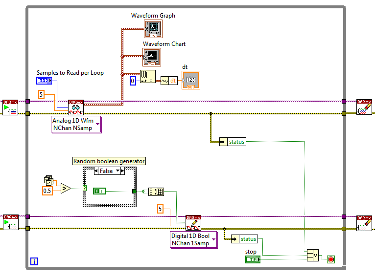
In fact, I think that one of the biggest problems is that you restart your digital task inside the loop every time. Attached is the revised for you to try code, the loop now looks like the following:
Notice the DAQmx beginning is now called before entering the loop for the digital task. Rather than use a wait function, you can use the samples of reading parameter so that the ratio of samples to read / sampling frequency is equal to the length of the loop you want (DAQmx Read blocks until the appropriate number of samples have been received). I also put the two tasks at the same time, so you can now write digital data while the DAQmx Read waits for the desired number of samples.
Devices of simulations are often useful, but trying to compare the performance it is always better to have the actual hardware. USB has particularly high latency 1 time of loop ms unfortunately probably not going to be achievable, but accurate performance will be dependent on the system. Try to run this code and see what results you can get - if you always replace the samples then you will need to increase the number of samples read by loop (and therefore decrease the rate of loop).
I hope this helps, don't forget to let us know if you have any questions.
Best regards
-
Continuous data acquisition programming
I wrote a program that I use to get the measurements continuously to a load with the DAQ assistant (attached) cell. I want to measure load values every 0.5 seconds and record each value using Scripture in the action file. I'm having some problems with getting the output file, I need. The parameters of the DAQ assistant are:
-Continuous measurement
-2 Hz sampling frequency
samples - 1800
- and a waiting period of 900 seconds
I want to be able to hit stop them at any time and at the end of the program. However, what is happening is that the program continues to operate until the 900 seconds is over. Is it because I made it clear to get samples of 1800? If I leave it blank, it defines a number itself. I read somewhere that the definition of the value-1 allows an infinite number of samples, but that returned an error.
Another question, I'll have, it's that if I allow the program to run after the timeout I put, it inserts a header after every sequence of timeout. I can't understand what is with wrong with my code, thanks for any help.
Basic arithmetic. 1800 samples/2Samples/s = 900 seconds.
Why accumulate so many samples at once? Reduce the number of samples at 2 and just wait 1 second for the Stop button to be recognized.
If you don't want a header for each segment, then uncheck that in writing to the configuration of the action file.
-
Treatment of LabVIEW data and high speed data acquisition C
Hi all
I am designing a data acquition VI high speed of 3 cards acquition of data at the maximum speed. Data cards are PCI 2517 Measurement Computing. The sampling frequency for each card is 1 M samples/second, if the total sample of M 3/second of three cards. Problem is the LabVIEW drivers and the screws provided by the provider works very well just for a single card at maximum speed, but does not support multiple cards at maximum speed. Their technical engineer advised me to write code in c#, C++ or VB.NET for this data acquition high speed. If I use C forever, I would like to use LabVIEW for processing of the acquired data to data acquisition. I came across a few examples that suggest the creation of dll C code and then calling it a LabVIEW. But those who have programs simple and none of them speak in C data acquisition. My questions are,
1. is it possible to call a C data acquisition program high speed of labview and not work in any kind of present of buffer overflow?
2 would it not simple best to use labwindows CVI?
3. is there another alternative solution that I'm missing?
I'll appreciate all the entries.
Thank you!
Nilesh-
It's pretty easy. Arguments for CINrun must match wiring. You can wire your CIN function block and say LabView to generate the C interface code to begin.
Here's my pairs for the ASIO audio project.
All the best,
Terry
-
Is "Introduction to data acquisition" by R. King a good reference for learning programming of data acquisition? Or can anyone recommend a better text.
Why don't you start hera.
-
How to program dynamically data acquisition?
The question may seem, I want to dynamically change the settings of a data acquisition card (DAQmx). The idea is to have a loop event caputures GUI and the other while answering the while loop DAQ events. It's something like loops PRODUCER-CONSUMER. However, I can do all thing once, but not on the fly. Any suggestions as to how we can achieve this?
Thank you
Thanks for the comments. I solved the problem with the traditional approach. Here is the graphic interface to work.
-
Is it possible to change the name of data acquisition device?
Hi all
Is it possible to change the name of device of data acquisition in a pragmatic way?
I wish I had at the beginning, when I start the data acquisition control a name that my .net program assigns to the DAQ card. Is this possible?
Thank you
Virginia
Ashly thanks!
Virginia
-
data acquisition won't taste at the specified rate
Material: C - DAQ 9178, AI 9239, inside a servo and an encoder potentiometer module
Setup: I use the 9239 to measure the angular position of my servo and encoder of trees by streaming came pressure pot of the servo and my encoder. I put the sampling frequency on the DAQmx - Schedule VI to 100 Hz.
Problem: I don't think that my DAQ is sampling data at 100 Hz because my VI registers more than 10 000 data points for a 10 second test. In addition, every time I have save my data in a text file, the vector of time my test data resets after a number of iterations.
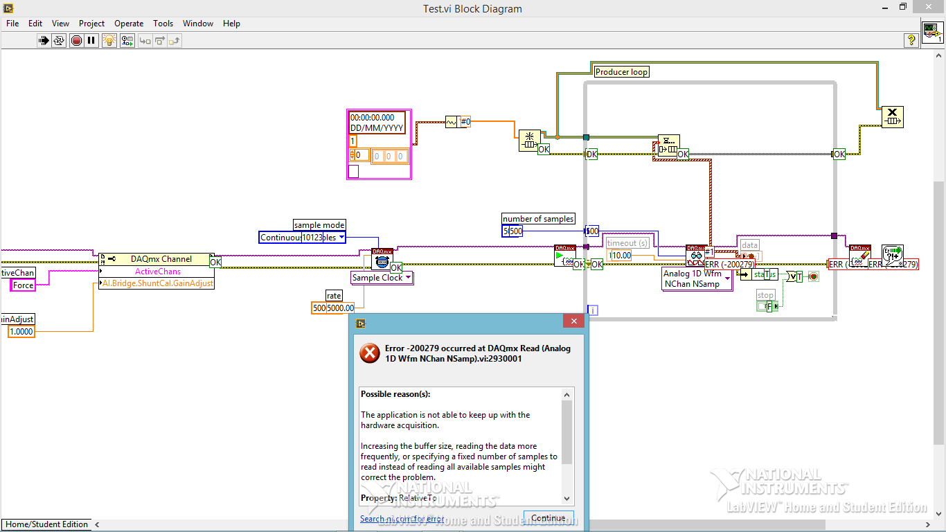
To debug, I tried the following configuration:
I've defined the sampling frequency of 100 Hz (or is that s/s?), the samples per channel (size of buffer for continuous mode) at 2000 samples, number of samples per channel up to 10 and loop milliseconds timer on my VI at 10 m accordingly, data acquisition would send 100 samples per second (or 1 sample every 10 ms) on my PC buffer (which could store 20 X that amount). Then LabVIEW would read up to 10 samples per loop iteration (which is itself ~ 100 Hz) and work with these 10 samples inside the loop. However, since the loop is operating close to the sampling frequency of data acquisition, then LV should only work with 1 sample each iteration of the loop (100 Hz / 100 Hz)-not the 10-sample-max that I specified.
However, I stumbled on "error-200279: the application is not able to cope with the acquisition of material" when I ran the program. Why?
My code and materials should be easily able to cope with data acquisition - at least the way I put it in place
This whole situation wondered my fundamental understanding of data acquisition timing, so I would really appreciate an explanation of exactly how to deliver DAQmx uses data synchronization, why my DAQ sample at 100 Hz, and how can I fix the calendar specified by the user.
Thank you!
aeroAggie wrote:
The C - DAQ 9178 there some minimum sampling rate I will not meet?
It's actually the 9239 that limit your sampling rate. Read the data sheeton page 5 there's available data rates. In short, your data rate allowed is 50kS/s / n, where is goes from 1 to 31. 50 k/31 gives you 1.6kS / s. So, it's the minimum sampling frequency that can be used.
-
data acquisition stops automatically
I want to stop assistant DAQ automatically after a period of time, so I created this VI.
When I start the program, it work and after reaching the value of time specific 50, the graphical indicator ' looks like "stop, but wait after 9999 second, the graphical indicator suddenly see a lot of data that seems to be taken for the 9999 seconds, what is happening? After that, it gives an error saying:
Possible reasons:
Attempted to read samples that are no longer available. The requested sample was already available, but has since been replaced.
Increase in the size of buffer, most frequently the reading of data or by specifying a fixed number of samples to read instead of reading all available samples would correct the problem.
Property: RelativeTo
Corresponding value: current playback Position
Property: Offset
Corresponding value: 0Task name: _unnamedTask<100>
Data acquisition cannot be stopped like that?
Thank you
Not quite. Like this.

-
Data acquisition in LabView for other suppliers DAQ cards that NEITHER
Hello
I am a beginner in LabView programming. I have a 32 channels base PCI card DAQ (i.e. PCI-1602 of the manufacturer, ICPDAS) and I want it to interface with Labview 8.5.
So how cards DAQ in Labview 8.5, which are manufactured by other suppliers that NEITHER? Should I DAQmx (or some other driver) for that?
What are the other drivers/components required to access of data PCI-1602 (device) of LabView 8.5 acquisition card?
(1602-PCI card driver are installed in my win XP and dispalyed in Device Manager).
Please provide some tutorial above mentioned the problem to interface.
Please guide me in this regard. Thank you
Waqar123 wrote:
Hello
I am a beginner in LabView programming. I have a 32 channels base PCI card DAQ (i.e. PCI-1602 of the manufacturer, ICPDAS) and I want it to interface with Labview 8.5.
So how cards DAQ in Labview 8.5, which are manufactured by other suppliers that NEITHER? Should I DAQmx (or some other driver) for that? You will need the drivers from the manufacturer, of the Board of Directors. In your case, "ICPDAS.
What are the other drivers/components required to access of data PCI-1602 (device) of LabView 8.5 acquisition card? Same as above.
(1602-PCI card driver are installed in my win XP and dispalyed in Device Manager). Ok. Then take you care of my 2 answers above.

Please provide some tutorial above mentioned the problem to interface. To learn more about LabVIEW, I suggest that you try to watch some of these tutorials.
Please guide me in this regard. Thank you
According to what you do with the DAQ cards, they can do the job however, from experience, there are some functions that I could achieve with the cards NOR that I couldn't with 3rd-party maufacturers. This does not mean that this is your case. However, it is worth noting that it took me a while to understand why the code has worked with a single data acquisition card (NOR) but not another (Non-OR).
The drivers that you have installed may or may not include examples and code in VI. They may be DLL. If this is the case, you can write LabVIEW "Wrappers" around these functions, as it will simplify your life. If the drivers are in the form of DLLs, and there are no examples of LabvIEW or available VI, you must read on node library function call.
R
-
USB multi channel data acquisition
I use the VI to arduino HC-06 bluettoth of data acquisition. I would like to acquire data multicahnnel
Could you suggest me how to acquire multichannel data from USB? To do this, how I have to program the arduino?
The crux of your property doesn't do anything since you not write anything.
Why you set the number of bytes to read at 8? You send more than that. You should be able to set it to a high number, such as 1000. Why do you use a dbl for this control?
-
Hi all
I'm new to LabVIEW
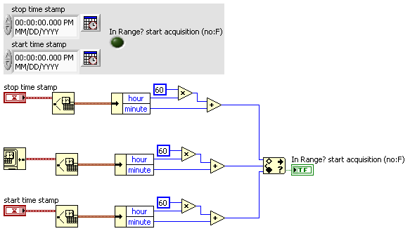
I want to create a program that can start acquiring data at 05:00 and stop at 19:00 and restart at 05:00 in the next day and so on
The ilustration is as below:
05:00 September 20, 2012 beginning of data acquisition
19:00 September 20, 2012, stop data acquisition
05:00 September 21, 2012 beginning of data acquisition
19:00 September 21, 2012 stop data acquisition
and so on...
Can someone help me on this please?
I have attached the VI below
Thanks in advance

OK, ok... im just a padawan! BTW, take care of your stress points...

-
Code error-200279 for data acquisition
Hi all
I am trying to build a small program of data acquisition, but I get a 200279 error telling me to increase the buffertime. What I am doing wrong?
Andersson wrote:
No, you're right. I don't get the error, I turn off highlight execution.
It seems so. I did not understand why he would come with an error during the audit of the code with the bulb. It seems like what I discovered on www.ni, one can avoid the error of initialization of certain data for the chart.
Not sure if I got it 100% correct however. Here is the link:
http://digital.NI.com/public.nsf/allkb/A647A1BE3DA8336786257AAA0066B45B
I don't have any other loop in the installer. I'm sorry for the confusion with the name 'producer loop. It's the only loop in the code, I deleted the rest to refine the error.
Is the conclusion that the program is good? Or do I have to do something to remove the error?
The table has nothing to do with your error. It's strictly highlight execution.
When you configure a continuous sampling, start the collection of data at a given flow rate. It is so big a configuration of the buffer. There is an article that tells how much room it is exactly, but for the sake of argument, let's say 10 seconds worth of data. In normal execution, your code runs pretty quickly that she is able to empty the buffer as soon as the data are acquired. But when you enable execution of climax, your VI slows down to a crawl so that he can show that you step by step what is happening on each wire. Your data acquisition always occurs in the background. Execution of idle is to take much longer that data are acquired. Within one or more loop iterations, you have filled the buffer and get the error message.
You cannot use point culminating performance when you use a device of data acquisition in this way (or VISA ports either) where data are sent continuously at a speed that is independent of speed, the code is executed.
-
Problem of reliability data acquisition PXI-4071
Hello
I'm having a problem of reliability using my 4071 Pxi digitizer mode.
I have a number of tests that use the SMU-6363 (usually configured for DC) analog output to provide a stimulus for our own device, which has a number of a/d converters. We use the PXI system for calibration and testing.
1. I select a voltage ranging from tensions.
2. program the PXI-6363 to drive this tension
3 TIME about 10ms to settle. Note there no discrete capacitors or resistors in the circuit. Everything is parasitic and would generally be under the nF mark and less than 10 ohms
3. configure and Initiate() acquisition of data with the PXI-4071. In general, I use a sample rate of 1000 s/s and get about 30 samples (worth 30 ms). Activation is immediate and I used the default a queue time, 0, set the time and it doesn't seem to make a difference.
4. measure the voltage with the CDA. For debugging purposes I have sometimes made twice once before calling Initiate() and once after. The after is normal. The time required to measure the ADC is shorter than the acquisition time, but regardless of stimulation by the SMU-6363 is constant
5. extract the waveform.
6. the average waveform and compare the value of ADC measured by applying tolerances etc.
Here's the problem: it works well most of the time. But only 0.1% of the time (1 on an acquisition of 1000), I get 8-12 samples that are close to 0. It sounds like a problem of time settling (on the surface), but no matter the amount of wait time data, I always get this behavior. Not only that, but the tension before the call to Initiate() in height CDA, it always confirms that the motor voltage is already set to the programmed value. Nevertheless the acquisition presents near data 0.
So far our independent ADC always reports the expected before and during acquisition (100%) voltage. It's like the DMM input is disconnected during the acquisition during a period of time, because we have confirmed that the voltage is already present prior to the acquisition (component can). I have no errors the insider or FetchWaveForm calls. I still have all my samples. And 99.9% of the time that everything works as expected.
The DMM and ADC are connected to the same point and both are referenced to ground, and as I said before only the parasitic capacitance and resistance (cable). We use a matrix of switching (PXI-2530 (b) to make these connections. We almost always use 51/2 digits and 10V range for data acquisition.
Hello
I thought about it and was going to repost but am distracted.
The device with the ADC also has a mux and switches the mux to an internal node. It only switches when measuring and is open at other times. There is a race condition where the acquisition starts too early and maintains the acquisition after that the switch is open. Unfortunately I don't have the option to trigger.
I forgot the internal mux that I had designed the test years ago and I did some updates to improve the stability of the test. That's why we start the ADC measurement when acquiring.
I just added a routine to reject samples below a threshold
-
How is data acquisition works in Labview
Signal Express is a software from National Instruments project (evolved from the previous software as recorder of NOR) which offers basic data acquisition features: acquire signals, signals, filter, log file, displaying output. LabVIEW is a programming language that allows you to do all these things, but much, much, much more.
If you use a LabVIEW so you need not Signal Express. You use DAQmx features in LabVIEW to acquire data of your DAQ hardware. Start by reading http://www.ni.com/white-paper/5438/en. Actually, there is a lot of information on DAQmx. Look in LabVIEW in the Finder of the example. Search ni.com DAQmx and filter on the tutorials.
Maybe you are looking for
-
How to interface LabVIEW 64bits for cRIO
We need LabVIEW2013/64-bit interface with a chassis cRIO (cRIO-9068). LV64bit doesn't have an interface of development for the cRIO - target cannot be imported into the project. What are our alternatives to the LV64bit interface and cRIO? (1) TCP/UDP
-
T61 and Windows compatibility 8
Any person in charge of Windows 8 on a ThinkPad T61? Is the case, is there incompatibilities? I am currently running Vista Business 32-bit on my T61 but I plan to switch Windows 8.
-
When you add a user with an id of lobbyadmin, is it possible to give this user a role of QoS.
-
Why is there a shadow under the math Input Panel?
There is no shadow under it when I open math Input Panel. I use Windows 7 Ultimate, SP1 on Intel Pentium Dual core (E2180).
-
laser printer that keeps appearing as 'offline '.
Having a printer laser Samsung network (not wireless) guard appearing as 'offline' on my new computer Win 8 and I must add again (by adding the printer menu) before that it will work. The network printer works fine on my xp and win 7 computers that