different pressure readings
Hi members of the community.
I have recently implemented a program using LabView 8.0 that works on my Dell laptop.
I'm always collecting data from four different channels - AI po, 100 Hz, 100 s/channel
I'm collecting data:
(1) linear encoder #1
(2) linear encoder #2
3) responsible for the output of the cell, after conditioning of signals - always in tension, output voltage is always positive
(4) voltage of the load - DC cell
My questions:
(A) for a reason any tension that I read with a DMM directly on WRT (4) ground is disabled by 2v. All other voltages are not compensated. Why?
(B) when I run the program on a Sony Vio laptop, (3) signals are very loud +/-2V type. Why? All other signals that identical, (4) are always offset by 2v.
Thank you for your attention and any valuable contribution
-Erick
Hi Erick,.
It is sometimes easier to use the measurement and Automation explore (max) to work things out. Here, you can set up a quick data acq. (material for). You are using the differential-input mode. Is the output of sensor DC? If Yes to both, then it is surprising that the DMM measures differently than the DAQ hardware.
Opening MAX (Start\Programs\NI\Measure...), find your material (NOR), open the test Panel...
If the issue is not resolved using differential inputs - what OR-DAQ hardware is connected?
Chance/Cheers!
Tags: NI Software
Similar Questions
-
Where can I go to learn more about the scale of pressure readings of different devices to HAVE?
E.g. I have a sensor Vaisala HMP 60 RHT. How I don't know what scale of pressure readings to get the good HR? I've seen values (for example 20 in the linear range of the Vaisala HMT 100), but I don't know where it comes from or why it is chosen. In which case it is important, I use several devices HAVE (thermocouples, MFC, of RHT) on a NOR-6343 USB Board. I really want to learn more, but am finding very difficult/complicated information. Thanks for all the help and advice.
Hi DHagan,
I think that this article might help you.
Best,
Carmen C
-
Find the difference of pressure between the two transducers using a NI DAQ 6008
Hello
First of all, I'm a relatively inexperienced LabVIEW Developer, so my apologies in advance if this message does not have something, or otherwise lacks clarity.
I try to develop a VI as follows the pressure difference between the 2 EME 3100 pressure sensors (4-20 my), related to two different pressure lines, using a NO-DAQ 6008. I would like for the acquisition of data to read the two transducers, then have him find VI the differential and write this differential in an Excel file.
The data sheet for these sensors may be found at: http://www.gemssensors.com/Products/Pressure/Pressure-Tranducers/Sputtered-thin-film/~/media/GemsNA/... It is a 3-wire system, with a voltage between 8 - 24V. I use an external power supply of generic brand to power sensors, which provides a maximum of 24V @ 4A.
I drifted my physical connection (for the two transducers) this thread http://forums.ni.com/t5/LabVIEW/I-am-having-trouble-Omega-PX4200-Pressure-Transducers-to-where-I/m-p... and am relatively certain of the accuracy of the information. For purposes of signal conditioning, I use a 500 Ohm resistor between the signal of each transducer and the Earth wire. On the side of software, I use the latest version of LabVIEW (2011) as well as MAX on a Windows 7 64-bit machine.
In an ideal world, the sampling rate would be as high as possible, but 4 samples per second would suffice for all purposes useful.
Given this goal, are there any sample of VI (especially for MAX, which I have not yet used) who would be similar/applicable to this project, specifically, regarding setting a sampling frequency, calibration of the transducers or affecting the pins/channels appropriate? All resources would be greatly appreciated.
Kind regards
MG Wilkinson
Measure the voltage between the two resistance (resistance by probe 4-20 MA) using the differential inputs of the x 600.
When you configure the task, you can read several entries at once, by entering in "Dev_ / AI0:1" in the physical channels and using the "several channels / {unique |}". multiple} samples"polymorphic instance.
600 x can read 1kS/sec.
Do maths/conversions on the table, and then simply subtract the two tables.
Could also take some samples (10-100) at 1 kHz and their average together, give you a smaller rate effective sampling but with less noise.
A loop of producer-consumer would be good architecture here, let the daqmx reading live in a loop and sends the data via a queue to a 2nd consumer that performs mathematical operations and write to a file.

-
get the values of the different acquisition channels
Hello everyone,
I finished my project and I want to do something and I did not how. I am acquising three signals from three different pressure sensons with the use of the DAQAssistant configuration to acquire form three analogue ports (there is a screenshot it below) and after it is shown in the same graph (second picture below).
This works fine, but my problem lies in the fact that I want to measure the maximum value and the value of the minimum pressure of each channel and always it is measured the first of them. I divided the measures in time-slopes as it is shown in the last picture. I have tried every single Vi of part manipulation of the function range signal, but I'm still not in the way of their use or I'm totally wrong actuing in this way.
Could someone give me a hand?
Thanks in advance.
Best regards
Miguel.
Really, we do not have enough information to give you good advice, but I can give you some generic advice. If you want the max and min an array of values, values use the Max & Min table from the palette of Array. Unfortunately, the DAQ assistant returns the type of dynamic data, which can be either a table of waveforms or waveform unique depending on how you do. Configuring your DAQ Assistant, it seems you are getting a picture of waveforms, but to use it as a form of single wave. Just after taking the data, convert your dynamic data type data type in a table using waveforms the DDT express VI in the Express-> palette of data manipulation. It would probably break a lot of your code, and it's a good thing. Broken parts are parts that are probably causing you problems. You can now use the index table to get the individual waveforms to the table and get elements of waveform for the picture of the waveform data. Use this table with table Max & Min to actually find your max and min values.
Alternatively, you can use Split Signal of the Express-> palette Manipulation of data to split your output into three unique waveform signals. Each of these signals can be plugged directly into the table Max & Min (LabVIEW will be script in the necessary converter). However, I highly recommend that you do NOT. It leaves you the problem that your data type is not defined yet, as this is always a type of dynamic data.
Also note that the use of globals as seen in the pictures of your code is a bad habit that can lead to all sorts of problems. However, I can't offer a lot of advice on how to fix it without the rest of your code (Tip: will probably involve some shift registers). Please post your screws if you have questions, so we can offer the best advice.
-
Variation of thermal EMF of the PXI-2530 modules
This message/question is a companion of my the most recent message in another thread.
In addition to watching some resistance higher than expected that affected current measurements using modules PXI-2530 multiplexer 4W topology, I saw systematic variation in track-to-track blood pressure measurements. Tensions would increase gradually through the 16 channels in a configuration by measuring the voltage at the terminals a resistor 1.5 kOhm with 0.5 au crossing (75 uV). I've identified that the thermal EMF of the reed in the PXI2530 module switches is on the same order of magnitude of these measures and set out to quantify the differences EMF thermal track-to-track between my three modules.
Test method: I have a TB-50 which is configured to mux the signals of tension for a DMM. I connected each of the four DB-50 one cable of 176 pins to this block and collected with a PXI-4071 pressure readings set to 7.5 digits precision in the range of 100 mV and > 10 GOhm impedance. For most channels, it took several minutes for the voltage stabilize - or at least appear that it was to stabilize.
I enclose three graphs. Note that the vertical scale is the same on each.
Data that triggered this survey was collected with MUX1, via connector P2 to voltage. The magnitude was not quite the same-probably related to the phenomenon of stabilization time, but obviously the worst group of channels three multiplexer modules.
The three modules were all bought at the same time (about 2 years ago), but had only limited its use in the first year or more. The three now have various 'mileage' based on my use. But MUX1 clearly behaves differently two other modules. The
I changed my test conditions to spend 0.5 au via a higher resistance to thermal EMF less important. The PXI-2530 sheets indicate that thermal EMF must be less than 50 uV. In most of my measurements, it is. But not for MUX1!
Any thoughts?
Thank you
Jeff
Hi Jeff,
You can check that all the three modules are PXI-2530, not PXI-2530 b (while, as the PXI-2530 b parts slightly higher thermal emf)?
Specification of emf thermal 50uV of the PXI-2530 is a typical value, is not a guarantee of spec. See a few channels higher than the spec is not a cause for alarm, but it shows that we must take account of this in our measurement error. Note that the industry standard for the technical measure thermal emf is to close the relay, wait a few minutes and then take a measure of tension. For example, if you scan through a switch faster than a relay per minute or so, the thermal emf will be less predictable and stable. A single module performs worse at these low voltages is not indicative that this module is a failure, etc. the module is fine. Unfortunately, the reed relays have more emf thermal relay of the armature, mainly because of the many layers of metal in a Reed compared to a frame (each metal junction is a source of emf if these metals are not the same).
Thermal EMF is proportional to the temperature, it may be interesting to note the position of the chassis of the less powerful module. Placing hottest modules (scanners, Ara, RF, etc.) will reduce the thermal emf.
-
Is there a single SCXI module adapted to the entries for mixed probes?
I'm trying to set up an SCXI system to receive signals from a number of different types of sensors. I have a large number of thermocouples for which I decided to use the SCXI-1102 module. I also have a unique pressure sensor (unknown spec so I'll assume type of strain gauge), a unique accelerometer (once again, unknown technique) and possibly a few tensions ahead right (unknown County and spec so assume - 10 v to + 10 v Beach max).
Is there a single SCXI module through which I can acquire voltage signals, accelerometer and pressure sensor? Or maybe just use 2 modules instead of 3 if I have a SCXI-1530 for my accelerometer and an another module for the tensions and the pressure transducer? I was watching the module SCXI-1121, which looks promising for the tensions and pressures but then was unsure as to what block of connection to use for the combination of signals (possibly, I could live with a - 5V to + 5 v range if necessary).
(Additional info: I use TC-2095 blocks with my SCXI-1102 module, can not really use spare entered on those voltage inflows).
Thanks for any help.
CASE NO.
It's expensive,
Thanks for your inquiry. You obviously already did a lot of research on this issue. I fear that it is unlikely that you will be able to use a single SCXI module to perform any function you listed. Necessary accelerometers such air conditioning specialist, it will take a module - as you mentioned already, something like the 1530 (4 channel accelerometer input module) would be ideal.
However, you have a number of different options for the pressure, voltage and temperature measurements.
For example, you could buy a mudule 1520 for your measurements of pressure and then use a generalist 1102 b for voltage and temperature (need you the connection block insulated from 1303 to condition the thermocouple readings... and work around the CYC technology for pressure readings).
Or, you may use the module thermocouple 1102 for your temperature readings and then use a 1102 b to take pressure readings and the pressure. Of course, that would require making your own bridge to the pressure sensor configuration, but this should be pretty easy.
Before making any final decision, I would recommend that you call your local branch of the NC and speak with a sales representative. Perhaps, a member of the sales field staff might actually come see discuss you it face to face.
Finally, it looks like you have a number of ways relatively high for some of your reading, is why you decided to use the SCXI platform. I was just wondering if you had considered compact DAQ (cDAQ), which combines the DAQ hardware with signal conditioning. Top spec, ease of use, lower number of channels. Swings and roundabouts I guess.
I hope this has been of some use to you.
Best wishes
-
Cannot detect the limits of reverse front/market
I have problems with the switches front and rear for my stepper motor system. When I created a NI Softmotion axis in Labview, no matter how to set limit switches, either appear as assets or both inactive, regardless of the position of the platform. I use for my end of race, photointerrupters. When I don't have the equipment under voltage, the photointerrupters works as expected and give a signal of 0 V when the platform is not the limit and V 5 beeps when the platform is at the limit. But when I try to use the Labview interactive panel (or in a VI elsewhere too) the limits are not detected and behave differently as well. I got a voltmeter connected to see how the tension behaved and pressure readings are odd. In a case when I tested the 'active' signal of each switch, was one of the limit switches to 6.7 V and the other was at 3.7 V, even if they had the same exact wiring and configuration. I'm completely stumped on how to connect these in the system so that they work or how to configure Labview to properly recognize these limits (meaning sourcing vs shipwreck and active State power). I searched the forums and manuals, but I can't seem to find a solution. Here are more details on the system:
The engine is now a platform back and stepper motor is powered by a Kollmorgen P70530 stepper drive. To communicate between the command of stepper motors and the computer, I use a cRIO 9076 with a NI 9512 in the chassis. To connect the end of race in the system, I used the NI 9512 connection block 37 pins. Switch in the photo that I use is a strong GP1A05 CIPO Photointerrupter with connector. For this photointerrupter, there 3 pinout: a Vcc input (voltage source), a GND input and output Vout. The SCR is supposed to be connected to a source of 5V and GND to the mass (obviously) with resistance to pull-up between Vcc and Vout (I use a k 10 Ohm resistor as who has what has worked for me in the past with this specific photointerrupter). Vout is supposed to give a signal 5V, then the limit would be active and 0V when it is not active. How I had connected the photointerrupter to the connection block 37 pin was as follows: to the limit before, I had the VCC to pin 9 (+ 5V OUT), GND was on pin 3 (COM) and Vout was on pin 1 (before the deadline). For the inverse limit, I had the VCC to pin 9 (+ 5V OUT) GND was pine 24 (COM) and Vout was on pin 20 (inverse limit). I also tried to connect terminals GND the switch of the photo to the GND (shield) pin on the plate at terminals without success either. In regards to Labview, I am running Labview 2011 SP1 on my computer.
If you have any ideas, I would greatly appreciate it if you would share that I am really confused with something that seems on the surface to be quite banal.
Thank you
Steve
Steve:
I am puzzled too-
Manaual I looked:
http://www.NI.com/PDF/manuals/372153d.PDF
Your PIN seems correct.
I assume you have a power supply connect to Vsup and COM.
Research on page 3-10 for sourcing of the shows without pullup resistance, have you tried remove the 10Kohm?
But watching page A-3 for levels of limits, it shows<5V for="" low="" and="" 11-30v="" for="">
I'm confused-pg 3-10 looks like the 9512 provides its own pullup still pg A-3 show the necessary voltages for entries.
I hope someone can clarify this.
-AK2DM
-
How can I measure the voltage of a signal?
Well!
I'm trying to read the voltage of a signal using acquisition data PCI-6229 card.i am giving the signal as an input to the DAQ card and try to read the voltage level. The range of my signal is 4.8 ~ 5.5 VDC but the results are not accurate, such as measured with DMM. My code is as follows:
1.i m using DAQmx create channel to create an analog input channel
2. then a sample clock with finite samples, sampels by channel and set the rate of iteratively
3. then I start the task
4. analog playback 1 DBL AK1 N sample d
Pressure readings I am differs widely that the actual.e.g a signal measured with DMM is 5v but when applied to the DAQ hardware and measured gives 6v.also I have to define minimum values and maximum in VI... If I put 4 to 5 maximum and minimum to measure a 5vDC signal it gives good result. , but if I change the maximum setting to 6v then it gives me results.also bad behavior is different for different signals for example when I measure a 6.5 VDC to signal that it shows me the voltage as 7.3V...
Photo of my code of VI is attached... Please answer... or give me another code that works fine at the voltage of a signal reading.
-
Map effective, where the keys never change, but the values change frequently
Hello
I need to spend many independent data (DBL, pressure readings) autour points, and they must be accessible by name (channels) from different parts of my program. Rather than having a huge cluster of many elements, I thought using a card.
My requirements are:
- The keys are unchanged for the life of the program
- Values change frequently and at the same time (currently 10 Hz, but it could grow to 100 Hz)
- All the data is quite low)<100>
What is the best way to store my data? https://decibel.NI.com/content/groups/large-LabVIEW-application-development/blog/2012/09/04/using-VA... Describes a table of effective correspondence. It seems optimized for fast retrieval of data; I don't know if this is it suitable for the storage of data fast and frequent.
The 'best' way would be different if I had a large set of data (> 10 000 items)?
Thank you!
Less than 100 items with keys of the strings, use the variant attributes and call it a day. For the largest data sets, I'll use a hash of the bucket scheme. The first step maps the keys to one of a fixed number of buckets. Each segment is a Variant, and attributes are used to resolve collisions. I put in other systems that are faster, but there is a cost of complexity of code highly it is really only worth paying if you are curious or that you have a very demanding application. Variants are almost plug and play.
Your other option would be a memory in the database like SQLite. Good API and enough speed for all but the most demanding applications.
-
How to create a type of "alarm" based on data time and acquired sensor system?
Hi all
I am relatively new to LabVIEW and have managed to create a VI that reads the data from the sensors voltage. Each sensor outputs 2 voltage values and I treat these values in the form of 2 different values DBL. I would like to be able to record each value of voltage as a base and then compare the readings of subsequent data with this base. Once the base is fixed, I want a sort of "variable", defined as 'TIME' to be registered at the time the base voltage is recorded.
The alarm should take place (or whatever it is Boolean TRUE value, I guess) once the tension to know remains within certain limits for about 2 hours. I know that I can compare the time system w / 'TIME' that the base voltage value has been saved. If pressure readings are beyond these limits, I would like the value of base zero voltage and the time PERIOD corresponding system again.
I apologize in advance if this didn't ' describes my problem, but if someone could help me understand the best way to create this code, I would appreciate it a lot!
Thank you!
-
Reading from the sensor to LabView via rs232 or Subvi problem
I'm quite new to LabView and not too experienced with instrument control so I was wondering if someone could help me to solve my problem?
Currently, I'm using LabView 2011 and I'm trying to read pressure DualGauge of Pfeiffer (TPG 262) pressure sensor and display the readings of two pressure on LabView. However, when I run my program, the pressure readings are not displayed - what is displayed are default 0.00 if same mBar pressure reading a reading of the display of the DualGauge probe. To connect the sensor, I use a RS232 cable and have managed to find the device on my device manager, so I don't think that the connection is the problem (I've also seen the port appears in the Device Manager, when I connected the sensor via RS232 and USB in my computer). I also use Subvi Pfeiffer in my code, and I suspect that the problem may be in there.
Attached is my code and here are links to the manual of the DualGauge and the driver of the software LabView of Pfeiffer
Double manual gauge - p. 23 and 68 are probably the only things related to the RS232 connection.
http://www.idealvac.com/files/brochures/Pfeiffer_TPG262_Operating_Instructions.PDF
DualGauge LabView driver - software Pfeiffer double gauge LabView driver 2009
Any help is very appreciated!
-Candice
You have not tested really do anything. Devices and MAX Manager displays only the com port that you added to the computer. It does nothing to verify that an instrument is truly connected. You might have the wrong settings of com or the wrong type of cable serial (null-modem is required). I suggest that you start with program such as hyperterminal, PuTTY or MAX and try something simple. It seems that you will receive an acknowledgement returned by the instrument when a correct command is received. Make sure that this simple step that happens.
-
GPIB crashing when running labview
I'm under labview 8.6 on windows 7 with a GPIB-USB-HS which is connected to a HP 34401 multimeter. This configuration is used to register the pressure readings. Recently I had an issue where labview will suddenly freeze and stop taking the pressure values. This accident occurs randomly and without warning. It may be triggered by pressure changes very quickly, but I'm not sure. Initially, I assumed from the computer, the drivers or the multimeter, but I have since excluded these sources. Now my only conclusion is that the GPIB has failed somehow. Is there anyway I can diagnosis the GPIB or fix this problem?
Looks like our problem was that we had a bad connection with our cable gpib, labview to expire causing waiting to talk to the instrument, it was connected to. We exchanged the bad cable and no more crashing. Thank you!
-
DAQmxReadAnalogF64 gives unexpected results with 9239 of Ni - DAQmx
Hi all
I use a NI 9239 with a laser sensor, and I would like to acquire some pressure readings of the probe which measures the height. It works very well with Ni Max, but not in C + c++ / MFC app I am developing. I get something that looks like amplidied noise:
1 reading scale doesn't seem fair (pressure readings I get from range - 2E9 to 2E9)
2 changes in what the sensor is supposed to measure does not appear in my measurements at all, there is nothing other than the noise (as if I were acquires bad chain - this I double checked)
I would like to get the same result as in Ni Max, but may not know what wrong with my code (below).Thanks for your help,
Ben
DAQmx Configure Code
DAQmxErrChk (DAQmxCreateTask ("LaserReading", & taskHandle));
DAQmxErrChk (DAQmxCreateAIVoltageChan(taskHandle,"cDAQ1Mod1/ai0","",DAQmx_Val_Diff,-10,10,DAQmx_Val_Volts,));
DAQmxErrChk (DAQmxCfgSampClkTiming(taskHandle,,10000,DAQmx_Val_Rising,DAQmx_Val_FiniteSamps,5000));Starting code DAQmx
DAQmxErrChk (DAQmxStartTask (taskHandle));Reading DAQmx code
DAQmxErrChk (DAQmxReadAnalogF64(taskHandle,NUM,-1,DAQmx_Val_GroupByChannel,data,5000,&read,));TRACE sends the readings to the debug output
TRACE ('%d points\n acquis', read);
for (i = 0; i<5000;>
{
TRACE("%d\n",data[i]);
}DAQmxStopTask (taskHandle);
DAQmxClearTask (taskHandle);Found the answer to this problem, the problem was in the function TRACE which data acquired to the debugger output. %D %f for the float to TRACE("%f\n",data[i values changed]) - things are great now.
Thank you
Ben
-
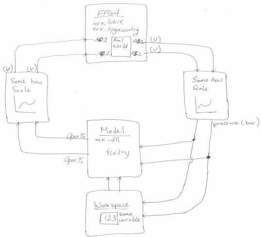
Impose a factor of scale between the model and FPGA
Hi all
I have a VS project configuration that unfolds on a real-time system. The project has an FPGA and a model. Some of the output of the cards of the OD of the FPGA model. In addition, some of the AI of the FPGA cards at the entrances to the model. Here's my problem. The AI FPGA gives me a measure of voltage, but the model takes only a pressure (bar) as input. This means that I need to convert my blood pressure using a table or a formula. How to make that happen?
Also, I want to use the same lvbitx FPGA and the same model of dll on various physical parameters. The only difference between these physical configurations is the forumla/table (for example, a different pressure sensor is used). Is a convinient way to say VS use different table games?
Hi oeua.uoeuau,
If you have a formula to convert the voltage in pressure, you can use a calculated string to implement. You just point to the computed in your Channel FPGA output and the inport of your model to the computed string. If you need a table of choice, you can create a model of LabVIEW that takes blood and uses a lookup table to get the pressure reading and the outport of LabVIEW model port in the inport else your model.
To switch between the different scallings, you can simply use a procedure to set a variable to be an entry or another.
See you soon,.
< brian="" a="" |="" national="" instruments="" |="" applications="" engineering="">
-
Problem writing data analog and entry of informed
Hi, I created a labview program that acquires 3 analog inputs (2 current and 1 tension), encoder out of whack angle and 4 temporary sensors. The Analogue inputs record against lunatics of an engine angle, once the engine has reached the point dead high simulateously in a single file. In another temperature record since signals file they are a lower sampling rate. Both files at the same time record by using the structure of flat sequence to the duration of the pulse encoder TDC events. The program works well with simultaneous recording.
However, I believe that in the file of analog inputs, the current readings are by crank angle but channel voltage readings are not. There a lot of zeroes inbetween pressure readings as if DAQ is not intervene for the tension. I can't understand why my program does that because the analog all the readings are in the same time of the sample and analog read the task.
I tried a program separate labview using only express DAQ and have the same 3 channels and saves the data in a file of lvm - it works even at the same pace. I do not wish to use Express functions in my program since fast flow and writing, he will miss values due to the explicit functions opening and closing of files (explicit writable) and creating the same physical channel (in daq express).
Please can someone help?
I have attached my program and a sample file entry.
Thank you very much
Notay
I think your problem is that you are indexing column 2 for voltage instead of rank 2. That's why you have only three elements in this table in the cluster.
Maybe you are looking for
-
I would like a step by step process apple a new airport express with time capsule base of connection (cable cat 5 150 Ft) with late 2008 macbook.
-
I need an installer for foxfire 8
My son got foxfire 8 on his mac, and then they sent him 9. then he thought that 9 would take care of everything, so he deleted foxfire 8 and Setup. and know 9 will not work, and when load US 8 it will not install on the computer. How can I get an ins
-
Een website die ik vertrouw wordt niet open, hoe kan ik said oplossen
Webside waar ik tot previous week een zaterdag altijd op speelde wordt nu niet meer geopende, Bij het aankllikken wordt direct internet setting door mozilla/firefox verbtoken, op mijn pc heb ik geen problems anything puts webside andereseplwebside sp
-
Need of recovery for Qosmio F20 CD
I lost the CD of recovery for the Qosmio F20-153, I have problems, and I want to the system recovery. What can I do?
-
Cannot send all word documents via email__
I could not send word by e-mail documents. I get the following response Your server suddenly put an end to the connection. The possible causes for this include server problems, network problems, or a long period of inactivity. Subject of XXXX', accou