Mode of scanning/FPGA for a CRIO by Veristand
Hello!
I have a small error using my CRIO 9081 use with CAN communication, here's what I did:
1. I use the CRIO with scan mode and customized it "Scan engine" and Ethercat for show my analog modules under VeriStand, it's ok
2. I use the CRIO with FPGA Scan interface (together under Labview) to detect my modules CAN, also ok
3 - then I wanted to see the CAN and analog modules, so I use this page:
http://digital.NI.com/public.nsf/allkb/0DB7FEF37C26AF85862575C400531690
And here's my problem:
with this method I am able to see the two modules with the custom device 'analytical engine and ethercat", which is really nice, BUT, impossible project VeriStand, the error message asking me to turn the chassis using FPGA, but then I lost the analog module...
So is it possible to run a project Veristand using both Scan and FPGA interface mode?
Thank you very much
Hi Vincent,.
When you tried to implement, you use the procedure described in the following document in the section use of Scan Engine and EtherCAT with NI 986 x custom device modules XNET ?
From what I remember, because you use a cRIO-9081, you will need to compile an empty bitfile for your target and place the controller in Mode FPGA hybrid mode on your chassis.
Could you post a screenshot of the error of deployment, you see?
Tags: NI Products
Similar Questions
-
Compatible for the cRIO 9063 VeriStand?
Hello
I currently have Veristand 2014 installed, but I'm not able to install veristand engine to MAX.
My 9063 cRIO is compatible for Veristand?
Thank you
Support for targets cRIO that running the NI Linux operating system real-time has been added in 2015 VeriStand
-
Why do I get an error when I try to change the mode of scanning by programming engine?
Hello
I have a problem with my EtherCAT system.
The system contains:
a RT PXI-8840
2 position with EtherCAT sensors
and 8 inverters with EtherCAT (with Softmotion plugin and xml file)
I use LabVIEW 2015 with RT and FPGA Softmotion module.
At the beginning of my code I pass the engine scan mode in configuration mode and then the active mode programmatically. It works well when I start my code with LabVIEW but I get an error when I use a startup application. The error code is-2132869095 (the deployment link has expired). I've tried also with a code containing just the screw for the switching of the mode of scan engine and nothing else. With this, I get the same error.
The problem occurs when one or more inverters are involved in the project.
Anyone an idea what I need to do to avoid this error?
Thank you.
Hello
the two cases mentioned in my last post have solved the problem. I have to follow this exact sequence and I expect that the analysis engine is running.
Now, my startup application runs.
-
Serial numbers for the cRIO-9081 Module
Is there a way for the FPGA in the cRIO-9081 to read the serial number, date of calibration of the NOR-9201 module installed in the cRIO?
I want to get this information and send it to my Host.vi, because we have a duty to provide information instrument document during a series of tests.
Thank you
Paul
Use a property node of the module to read the number of series/VendorId... but the calibration date is not stored. (FPGA code example shows NI9205 data)
Here a Fifo of DMA target host is used to send the data to the controller of the CR...
-
What is the MTBF method, used for the cRIO 9012, is the method of counting of Telcordia under what conditions? (Temperature, humidity, etc.)
Hi jojosalud,
According to the specifications for the cRIO-9012, the MTBF is 330 481 hours at 25 ° C; Question of Bellcore level II.
Kind regards
-
FPGA for PC via UDP connection
Hi all
Background
I am currently working on a project to interface an FPGA with a PC, to send a UDP load prepared on the FPGA for the PC. The FPGA is preparing a payload of 18 hexadecimal bytes from h00 8' to 8' h11 and then transmits it via a local network on port 1024, between the FPGA and a second network card in the PC, with static IP assigned to the second network card and the FPGA. Packages leave the FPGA and reached the PC (tested with wireshark) but the vi does not appear meet the payload and display it on the screen in the vi. The vi is based on that comes with labview and only has a few adjustments for most simply to write the final packages saved to a text file.
Problem:
Initially, when the vi was run the length of the chain kept evaluate to zero and so he perceived no bytes don't read from the port. I then inserted the flatten channel vi after the UDP read and before the comparison of string length (after reading something on the forum), now the length of the string is not evaluated to zero to 4 instead of this, I also changed the display to the spell option but the same 4 Hexagon keep coming through '0000 0000 0000 0D0A' , but they are not those who have been sent from the FPGA (are they an error message?) and not those taken over by wireshark. In summary, I seem to not be able to read the data of the UDP payload in Labview.
I tested the VI locally using the Protocol UDP send labview vi and vi (slightly) custom receiver and it still works. The receiver that VI is attached.
Any suggestions would be great,
Thank you
James.
You can share the wireshark log (preferably in a format based on text that I did not install Wireshark)?
Are you sure that is no firewall problem? If you are using a firewall, disable it completely for this network card or at least ensure that it accepts connections on UDP Port 1024.
In addition, set the UDP sender VI on another computer and see if you are still receiving data. If it works, compare logs wireshark compared to what is sent by the FPGA and search for differences. If this does not work, then you have a network like a firewall problem.
-
E:, HP ENVY, HP ENVY 4500 4500 don't scan pdf for MAC, only jpeg; used to work properly.
HP ENVY 4500 worked fine a month previously, now don't scan pdf for MAC, jpeg only. Also do not accept the file name. Is there a doctor of printing & scanning HP for MAC?
Hi Maryjon , thanks for getting back to me!
I appreciate the info.
I suggest to remove the printer from your printing system, using this document: uninstalling the software of the printer.
Once you have deleted, I suggest to check and repair disk permissions: function to fix the permissions of all utility disk drive.
I also run your Apple updates: OS x: Mac App Store apps and OS X update
After the updates, I recommend you to reinstall the series HP ENVY 4500 full feature software and drivers.
Good luck and please let me know how it goes!
-
Windows XP: internet connection
Windows XP: I access to internet in safe mode with networking; then for a short period in normal startup; but then I lose access (IE8, Google, AOL) online. I tried several times, sometimes it seems able to stay online as long as I'm using the installation, but if I take a break, I lose access and return in safe mode.
This question is submitted in safe mode with networking
Hello
Normal mode try to know what actually is the problem with the Internet connection and the components involved.
Maybe this can help.
For the wire connection - http://www.ezlan.net/debug.html
For a wireless connection - http://www.ezlan.net/wireless.html
-
Subject of load balancing. An arm mode require ESG instance for each requirement of LB?
Hello
Most document indicates an arm mode drawback is that for each LB (One - Arm) requirements, separate
Instance of the ESG is needed.
Is this true?
I feel that I can deploy an ESG for 9 balance of the load of an arm as the next parameter.
-Deploy an ESG
-Add vNIC 9 to the GSS and add the IP address of the LB for each segment. (EX. 10.0.0.1/24 to first vNIC, 10.0.10.1/24 to the second vNIC and so on...)
-Disable the routing
-Add LB VIP pool as usual.
I said '9' to limit, because there is limitation of VM vNIC 10, and 1 can be used for future uplink...
I'm sorry that I can't prove it by tests, because I do not have the test environment.
Number of subnets in 1 single cutting edge
A single cutting edge can actually be connected to the networks of more than 10.
Indeed 1 edge interface can be of the type: 'Delete', 'Internal', but also 'trunk '.
Use of the "trunk" type, you can create secondary interfaces and up to 200 Sub interfaces supported in 6.1.x within the same interface.
Now on your question: 1 m LBS per subnet
You can certainly have the same edge with several interfaces / subnets and configure VIP in each subnet.
Note: You must opaque (SNAT) mode under the pool to the guarantee of the response from the server will return via the Edge-LB.
The question I have is about: "disable routing."
Do you mean that the edge will not need any itinerary to meet clients. In other words, applications for all customers hit an edge-LB VIP comes from a subnet which exists on the edge?
If the answer to that question is 'yes '. Then, I agree.
If the answer to this question is 'no' (customers come from Internet, for example). Then, I disagree.
Dimitri
-
cRIO 9081 to the 9144 expansion chassis. FPGA engine mode or scan?
Our installation program runs VeriStand on a chassis 9081 cRIO using a FPGA personality. We wanted to add an ethercat expansion chassis 9144 to the system. Don't support the cRIO and expansion mode personality FPGA chassis runing VeriStand? I can't find much information about it, other than runing the system using the analytical engine.
Initially, we tried to run our system uisng the analytical engine add on, but the system had problems with the NI 9213 16 Ch thermocouple card. If one of the inputs is open it read the rest of the channels open. For example, if channel 5 is open, the remainging channels 6 to 16 would also read as at the opening. For this reason, we configure an FPGA personality to read inputs and outputs.
Thank you
You can do it. But you need to compile the FPGA in a hybrid mode:
http://digital.NI.com/public.nsf/allkb/0DB7FEF37C26AF85862575C400531690
-
I want to use some of my modules in scan mode and others in the FPGA mode. Although I could create a hybrid project, I can't do a VI implementation of two of them. I get an error as in the diagram I have attached. I want to read the analog inputs using NI 9239 scan interface mode and put out through 9269 mode of fpga. Is this possible? I'm kinda new to this.
Thanks in advance!
Of course, you can do what you were trying to here. You must at least two screws for this application. You will need a VI running under the FPGA target who can read and write the purple (FPGA IO nodes) nodes. You will need a VI running under the controller RT who can read and write variables, like the yellow node in your image. To talk between two screws, use the palette FPGA Interface to read and write controls and indicators on your FPGA VI of your RT VI.
This information gets you take off a little at the moment?
-
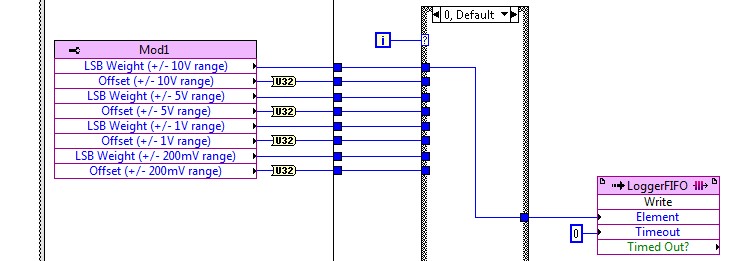
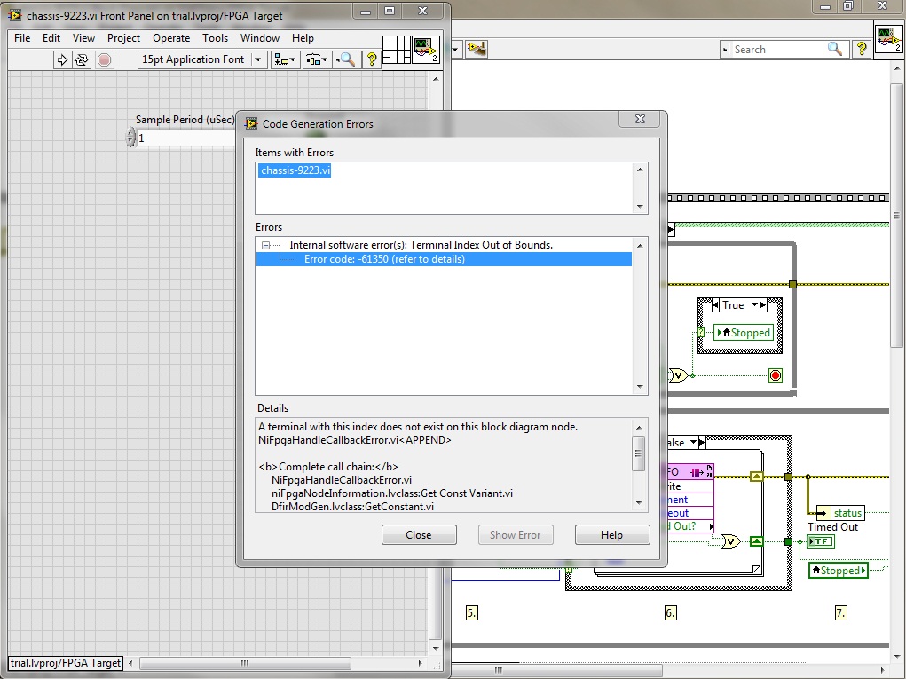
I get the error (in a popup window) when my VI FPGA code in chassis 9118 OR NI 9223 module compiled help. This error occurs when compiling the process (generating intermediate files, scene 7 of 7). How to solve this error?
Thank you
additional information:
Original error message:
-------------------------Errors:
Software (s) internal error: Terminal Index out of Bounds.
:-61350 error code
Details:
A terminal with this index does not exist on this block diagram node.
NiFpgaHandleCallbackError.vi«"" "String of full appeal:»»"»
NiFpgaHandleCallbackError.vi
niFpgaNodeInformation.lvclass:Get Const Variant.vi
DfirModGen.lvclass:GetConstant.vi
niLvFpgaMungerBrainwashIONodeCommon_Dfir.vi
niLvFpgaMungerBrainwashSingleIOGrowableMethod_DFIR.vi
nirviEIOMethodImplementation_SpecifyDFIR.vi
nirviEIOMethodImplementation_SpecifyDFIR.vi.ProxyCallerHi tesa,.
This is a bug that has been fixed in LabVIEW 2012 SP1. The number of CAR created for this bug is 332811 and as you can see in this link, it is already in the list of bug fixes.
Carmen C.
-
Hi, just got my new cRIO-9067. I have converted my project over the cRIO-9067 since the cRIO 9074. Same layout module, same engine, same scan code custom fpga, (hybrid mode). I have no problem of compilation for the 9074, which is a lower performance FPGA architecting the 9067 FPGA.
The final timetable for windows compilation shows that the timing is respected for all clocks - 40, 80 and 120 MHz (I use a clock derived for some code sctl). During the end of compilation, during the phase of gen bitfile, I get the dreaded time violation. Investigation of the breach indicates that it is not the custom code, it is not schema components. One of them seems to be linked to the card series OR 9870 I in the chassis.
Why? Is there anything I can try with the compiler directives for this problem? You would think that it would be easier to compile for the highest performance FPGAS...
OK, don't ask me how I thought this output - to run I changed nothing else than this: feed the I/O node a reference FPGA of e/s instead of configure the node via the menu "link to. It makes no sense, but the compilation succeeded when I did this.
I know it is because I created a very simple test VI in my project and made sure it does not compile without it.
-
configuration of the programming for the cRIO module?
Is there a way to programmatically access the configuration settings for the modules in use on a cRIO? I seeks to define the type RTD channels on the NI 9216 RTD by screws, not the exporer project module. In this way, when the system is established and sent to a customer, they would be able to change this without requiring source code.
Does anyone do this?
If you use the scan engine to read the entry (not in the FPGA), there is another property to set the RTD type. In the FPGA, you have just the weight of the LSB and the Offset properties.

-
Hello
I have a cRIO-9014 with a NI9505 DC brushed servo drive module and I would like to program the FPGA to PWM and encoder, quadrature, interfacing using the functions of intellectual property intellectual property mentioned in "CompactRIO Motor Control Basics Tutorial":
DX of encoder quadrature method (FPGA, using SCTL) .vi
Pulse Width Modulation (FPGA, using SCTL) .vi
I did a search at ni.com/ipnet but I could not find them.
Where can I find free downloadable IP cores for the blocks of PWM and encoder to include them in my interface FPGA program?
Thanking you in advance,
Manual
Found by myself (google search!) to:
https://lumen.NI.com/nicif/us/codepowelecguide/content.XHTML
Maybe you are looking for
-
I want to cancel a plan to ICloud 50 GB of storage, what should I do?
I want to cancel a plan to ICloud 50 GB of storage, what should I do? I have
-
I know this question has been asked several times, but I did these steps and still not get Defragmenter to work. My Disk Doctor said I don't have problems with my Defragler work program - but I don't have a C: drive not 'dirty '. I have Windows XP
-
This screen has field "Brose to the drivers and then select them. I don't know where to find the drivers. It seems to be a 6drives of choice to find the driver, the following: ACE (C :) Recovery (d :)) Drive local (e) HP_Tools (F:0 CD (g) GSP 1RMCHPX
-
Is blackBerry smartphones possible to determine the type of LCD display on a storm?
My LCD is cracked and needs to be replaced, so I need to know which two types of LCD that I have on my Storm. Does anyone know how to determine this without opening the phone? Thank you.
-
LifeCam vx-3000 does not work in Windows 7 for me.
I have a new computer. Corei3 530, 4 GB memory DDR3, 1 TB HDD, Intel H57 express chipset Intel Graphics Media Excellerator HD with Direct X 10 support. I installed the new firmware driver for Windows 7 on this site and clearly this webcam does not wo