Digital filter on the sample clock 6601/6250
Hello
I use a PCI-6601 (Dev1) and the card PCI-6250 (Dev2) connected via a cable RTSI.
I apply a PWM signal to the 6601 ctr0 (Dev1 / / PFI38) and activate the digital filtering (100 ns) on the respective task (measure of the period).
I apply an analogue signal to AI0 map of 6250. As I am interested in a sample of analog measurement when the PWM signal changes from low to high, I put the clock sample of the AI task source ' Dev1 / / PFI38 "and the side assets of clock sample"Insurrection. "
Everything works fine, but I have a question:
The sample for the AI clock is the task the filtered PWM signal or not filtered PWM signal?
Kind regards
Udo
Hi Udo,
Great question! Digital filters are actually not part of the subsystem of counter, but rather the line itself PFI. So, if you have activated the digital filter for a specific line of the PFI, the signal that you route to any subsystem of the PFI line will have already crossed the filter.
It's actually the workaround to the PFI filters on M-series / TIO DAQ devices when you are not using meter (materials of filtering on each PFI line but the DAQmx driver allows only the filtering part of duties of counter on these devices).
I also wanted to emphasize that the 6250 itself has 2 onboard counters, then you could do the same thing using just the 6250 (unless you use more than 2 meters). I hope this helps!
Best regards
John
Tags: NI Hardware
Similar Questions
-
Buffer the output AO, refresh rate is different from the sample clock frequency
Hello
I am an AO output in the buffer using a single channel. I have a stamp with a ripple of 200000 points with a triangular waves of a 1000pts each repeated 200 times. If I want a frequency of 1 Hz, I simply update this waveform 1000pts and if I wanted to 5 Hz, then 5000pts and so on. But there is some frequency that I won't be able to use like the refresh rate (the number of samples that I ask to update) is different from the sample clock frequency, which makes synchronization with the other difficult to trigger (incomplete cycle). Frequency 3 Hz (update 3000pts), as (update 7000pts) 7, 6 Hz (update 6000pts), 9 (update 9000pts)... 11Hz at 15 Hz and is not valid in the sense that the refresh rate is different from the sample clock frequency. That makes a whole lot of inaccessible CONFIGURED! Can someone tell me what determines the banned frequency? Is this something to do with the material?
concerning
One thing you can try is to change the number of samples per cycle. This cannot give the precise frequency accurately, but can reduce the average error.
120 Hz, the error is currently about 400 parts per million (ppm). The accuracy of the time base is 50 ppm, then this error is less than 10 times the inherent error due to the time base.
Consider this configuration: the closest nominal sampling you rate, you can get is 120048 Hz (1000 samples per cycle at 120 Hz). If your buffer contains 1200 samples per cycle, 100 copies of it would produce 1 second of data to 120,048 Hz. But if the buffer contained an average of 1200,48 useful Samper by cycle, you get the exact frequency. Of course getting 0.48 of a sample is delicate. But the kind of feasible. If you use 48 cycles in the 1201 samples per cycle and the cycles of 52 to 1,200 samples per cycle, the total number of samples per second = 120048. Average frequency will be exactly what you want. Instantly, the frequency is slightly higher or lower than the exact value. By an alternation of 1200, 1201, 1200, 1201... 1201, 1200 100 cycles that the Jig is fast. If you group all 1200s whole and all 1201 s frequency hopping may be more sensitive. If this kind of jitter is acceptable depends strongly on what you do with the release.
This technique is used in some systems of frequency synthesizer.
Lynn
-
Problems of synchronization of the sample clock with a frequency of a PXI-6229 counter!
Hi all, I'm having some problems with the synchronization of a frequency meter connected to a liquid flow meter (sensor only have 1 open collector output) with the sample of a PXI-6229 map clock. Someone there willing to give me a little help here would be appreciated?
The problem is that the reading of the meter in the whole loop blocks until the time-out period.
Suggestions for an alternative approach would be too good...

Source code attached.
BR,
/ Roger
It sorted another way!

-
How do you use the freqout as the sample clock to write data on the of 6224 PCI
Using PCI-6224, I try currently to export data using the freqout as a reference clock sample to a digital output channel. I plug the scope to see the clock on the freqout PIN. However, the data seem to be missing. How can I output the data correctly using the reference for timing? What am I missing that connects the two signals together? Any help would be greatly appreciated. I am writing this code in MS VS C++ and here's what I've done so far:
        int32       error=0;
        TaskHandle  taskHandle=0;
        TaskHandle  taskHandleFRQ=0;
        char        errBuff[2048]={'\0'};
    uInt8       data[8]={1,0,1,1,1,0,1,0};

    /*********************************************/
    // DAQmx Configure Clock
    /*********************************************/
    DAQmxErrChk (DAQmxCreateTask("",&taskHandleFRQ));
    DAQmxErrChk (DAQmxCreateCOPulseChanFreq(taskHandleFRQ,"Dev2/freqout","",DAQmx_Val_Hz/*Units*/,DAQmx_Val_Low/*IdleState*/,0/*Delay*/,10000/*Freq*/,0.5/*DutyCycle*/));
    DAQmxErrChk (DAQmxCfgImplicitTiming(taskHandleFRQ,DAQmx_Val_ContSamps,8));

    /*********************************************/
    // DAQmx Configure Digital Output
    /*********************************************/
    DAQmxErrChk (DAQmxCreateTask("",&taskHandle));
    DAQmxErrChk (DAQmxCreateDOChan(taskHandle,"Dev2/port0/line0","",DAQmx_Val_ChanPerLine));
    DAQmxErrChk (DAQmxCfgSampClkTiming(taskHandle,"/Dev2/PFI14",10000,DAQmx_Val_Rising,DAQmx_Val_FiniteSamps,8));

    /*********************************************/
    // DAQmx Write Code
    /*********************************************/
    DAQmxErrChk (DAQmxWriteDigitalLines(taskHandle,8,0,10.0,DAQmx_Val_GroupByChannel,data,NULL,NULL));

    /*********************************************/
    // DAQmx Start Code
    /*********************************************/
    DAQmxErrChk (DAQmxStartTask(taskHandleFRQ));
    DAQmxErrChk (DAQmxStartTask(taskHandle));
I think that the original code was operational. However, given that the data transmission has been set to finished, I had a hard time to visualize the data on my scope. By changing the value of DAQmx_Val_FiniteSamps to DAQmx_Val_ContSamps, I could easily see the data.
My mistake. I'm still learning here. Thanks for the time.
-
Hello world
After 10 years of LabVIEW experience I'm totally lost.

It's my first project with DAQmx and I do not know how to handle.

My configuration: Windows7. LabVIEW 2012 DevSuite; X Series USB-6366
My goal: trigger value encoder and 2 inputs analog
I would get a result for the value of the encoder and each of the two analog inputs for each change of the value of the encoder (not more! I do not want to sort a huge amount of data afterwards)
I was able to configure it with the measurement and Automation Explorer, but have no idea how to do that in a LabVIEW configuration.
Read all of the examples I could find the analog inputs and the encoder with SampleClock. This isn't what I'm looking for.
I would be very happy if someone could guide me to my solution.
I have attached the confiuration exported from the measurement and Automation Explorer.
Thanks in advance, best regards,.
Balze
P.S.: Sorry I got COMPRESS the *.nce file, because NEITHER allows you to attach files *.nce

You'll get there, but yes, the first exhibition to DAQmx is probably a little overwhelming. A few other tips based on your screenshot (I'm on LV2010 & can't open the code).
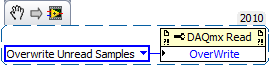
1. "allow buffer overwrites" is that a functional but description is not text. It lies under the Read DAQmx property node and must be configured before starting the task. Here is an excerpt:
2. it is usually (but not always) an available timing system to be used for all HAVE channels in a task just by the material. As a result, all channels to HAVE should be included in a single task. You can do this easily in chaining your call 'DAQmx create Virtual Channel' twice the job output and input/output error. Because the second call will receive a task refnum as input, it will configure the 2nd channel of AI to be part of the same task.
(It is possible to specify just several channels in a single call, but separate calls gives you the ability to configure different setting on the scale or range of entry).
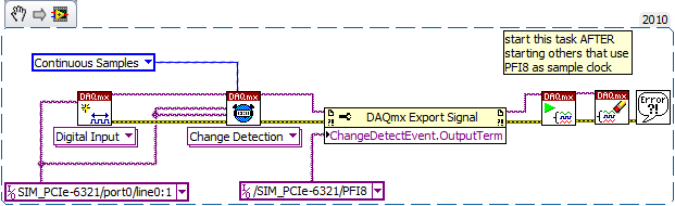
3. the 'random', which IA task gave you the error is due to the lack of sequencing in your attempts to start tasks. The question which is the fortunate success that happens to run first can (and does) vary from run to run. By combining the two channels to HAVE in a single task, this problem will disappear, but you want to be sure that the tasks of the AI and the counter are started * before * any clock signals come to PFI8.
4. "change detection" will be available for digital input assignments, not tasks of meter. And it is also generally supported only for a digital port a-bit value. Other ports then that support data acq clocked by the software on demand. I guess one of these questions is the source of your error.
On the boards of the M series that I used, change detection has been supported only on port 0 - I think that the same thing will be true for the X-series cards. The following took place without error for me using a simulated X series device. By selecting another port gave an error.
-
6259 analog integrated Output error with the sample clock
I run into some problems outputing a sinusoid of analog output with my acquisition of data using the sampleclock aboard. At one point, I was able to get the vi works pretty good and repeatable. When revisited however, I started to see error that the driver could not provide the unit with the points quickly. I was running at 250 k 1 k sampling rate a tone to one, but it seems only to be able to get about 20 k, sampling frequency. This creates a pretty rough signal, expecially when the rate fell to 8 k. I produce only 1 second of data.
See attached bmp. The I/O moved references aren't channels of tasks. Could be the problem? I'm a little frustrated because he has to be a very simple to create vi and I'm having all sorts of problems with it.
Hi klessm1,
I want to stress that the behavior you're seeing is atypical - under normal circumstances, DMA transfers must take place fast enough to keep the data in the FIFO embedded permanently until at least the max (2.86 MHz single channel) sampling rate. After saying that the error you receive indicates that we get no data for the 6259 fast enough for some reason - there are a few options at this point, it should get you operational:
Remove the need to transfer data to the device. As Sarah suggested, you can do so by regenerating the on-board FIFO. The FIFO output on the 6259 is 8 191 samples (shared between the channels), so if you build a periodic signal and this is a sufficient number of samples to characterize a period then this should be a viable option.
Try using interrupts instead of DMA. This may seem paradoxical since DMA is generally the fastest method of data transfer on our DAQ hardware, but something rings the Bell with the DMA transfer from your computer to the 6259. I imagine that you will actually have a faster rate using interrupts if that is the case.
You can configure the appliance to use only the quantity of memory onboard or interruptions using a channel property node DAQmx (Analog Output > General Properties > advanced > memory and data transfer)
Implement a delay between the start of the task and the first sample. If the problem is with the first DMA transfer latency (and not the total throughput on the PCI bus), then adding a delay before attempting to write the first sample should solve the problem. Some motherboards have been found to have a latency higher than the others (so the question of Sarah #3).
You can configure the delay with the property node Trigger DAQmx (start > more > Delay / delay units). This applies even if you do not explicitly have a configured start trigger.
I think the three above are good ideas to try depending on what you need exactly. I would also check for updates to the BIOS available for your motherboard that could address the issue (but it would be something that the manufacturer would be more known). I hope this help - made - know us how it goes!
-John
-
Synchronization of analog and digital output with the external sample clock
Hello
First of all sorry for my English, I will try to explain what I want to do.
I want my PCIe-6321 to send two custom signals (modification sawtooths) on a mirror controller. I would also like to generate output with my card at the beginning of each tooth of saw. Everything must be synchronized with an external k-clock signal of 100 kHz. The idea is that whenever the PCI receives a trigger to external clock, it sends two analog output voltages and when he received 1024 clock ticks it will also send a pic of triggering TTL. What I do is first prepare the map and after that in a loop sending and modifing the output values of the two signals and at the same time send a digital signal Boolean in each arch, so when's done it 1024 iterations of the loop I send an event to the digital port. Attached you can see.
The problem is that I don't know how to synchronize both. Can I use the sample clock just to the analog output? I can use sample for the two outputs clock, or do I need to use the output of the meter? If don't know how to use it here.
If I do nothing else bad/wrong, I would be grateful for feedback.
Thanks in advance,
PabloI don't know how but I find the solution. I'm generating more than a positive value (as I was triggered maybe very fast the oscilloscope has been absent there). If I put the sample clock of digital output to use the sampling/ao/Dev1 clock that it doesn't, but if I put to use the same source as the OD (terminal where my external clock is connected), but the trigger to start the DO to be Dev1/ao/StartTrigger this works. I don't really know why, but it does.
Thank you for your patience and your help. I put here the final code.
-
Reading and samples the sampling frequency using a fast external clock
Hello
I use an NI USB-6212 box to launch a search engine for combustion. I have a pressure sensor in the head and a wheel on the crankshaft. I use the beats A Quad channel of the rotary encoder as a sample external to the pressure with the sample clock. The idea is that I want almost the same number of points in each trace of pressure so that it is easy to average together. I seem to be able to do this at low speed, but I'm having issues at high speed.
Can someone tell me what I should have my sampling rate and samples to read together and how it effects my sampling when using an external clock? Samples per channel will affect the size of buffer and that matters? When I was high (10-100 kHz and about 1/10 * rate for samples to read) it barely read but as I put the lowest and lowest he read faster. Play with the settings a bit seem to affect how well it samples at different speeds. The engine is running at 3600 rpm and my encoder puts out 2500 pulses per turn on one channel, I'm looking at a frequency of 150 kHz effective sampling. However I didn't sample program with the engine operating at full throttle. I hung on the output of the encoder up to a scope and reads very well.
Are there opportunities the filter counter that I see in the manual of 621 x is enabled inadvertently?
Thank you
Xander
Xander18,
I suggest you move your screws initialization outside the while loop, as well as your narrow DAQmx VI. On my side, it looks like a new task is performed for each loop, which takes time. That a try and let me know how it goes.
-
Error on wait the next sample clock
Hello
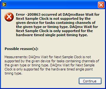
I need measure the speed using an encoder for a control application. I installed a sample external clock on CNTR0 (in another vi) and I wired CTR0_OUT to CTR1_GATE. I start the vi, then the measure of the clock vi speed sample and Labview displays the following error. I don't know what is happening, my measure is established for the sample clock and timing type single-point sample clocked by material and the error says that I do not have this? What's funny, is that the same app works if I am using the DAQ Assistant.
Thank you
David
Hey David,
I believe that the document I linked can be a problem, and I'll go ahead and make the necessary changes to be made to this document on my side.
The next issue I can see uses HWTSP on a windows machine. HWTSP is usually reserved for computers running real-time operating systems. These operating systems can ensure deterministic operations. On windows XP, windows may decide to treat another thread / process that can cause you to miss a sample (if you miss a sample that the default behavior is to throw an error).
With HWTSP, you will be difficult to get one without a real-time system faster sampling rate. Stamped acquisition will also have a large amount of latency for a control application.
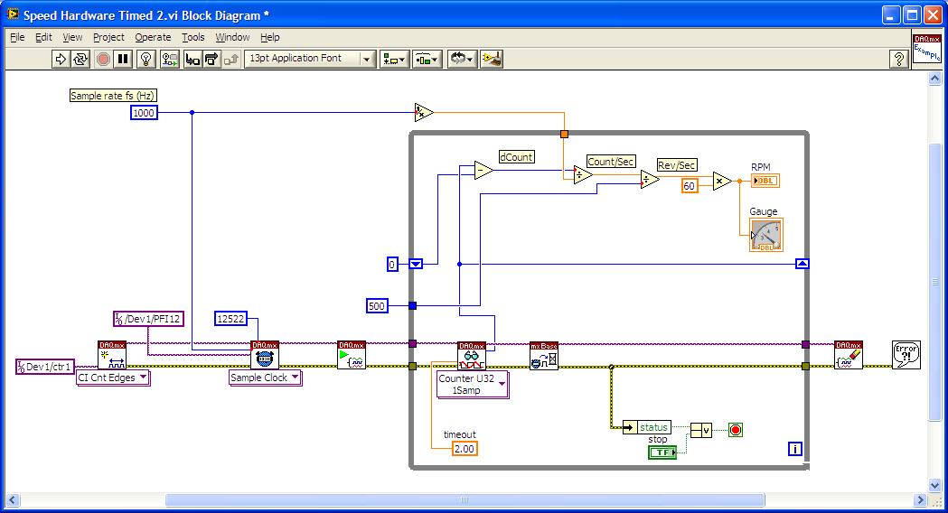
Looking at your code, I recommend trying a task of sampling frequency CI On Demand. Currently, your code is the edges and conversion of frequency/RPM. In addition, because of the lag phase with your sample clock, your current configuration has an error of ±1 count. This translates to error ±1KHz (on behalf of 9 to 1 ms it would be 9 kHz, 10 would be 10 kHz, etc.). Based on mathematics in your example, you introduce ±120 rpm of error. By a frequency on the task on demand, you can ensure that whenever you call the DAQmx Read, you get the last frequency within a tick of time base error ±1. Not only it gives a better accuracy, but as long as you keep the rate of fast loop, you will ensure you get the last frequency to the fastest rate possible.
Ensure that your loop rate remains fast is to remove the loop of your acquisition processing and placing him in a parallel while loop. This is possible through the use of reporters. Local loop in Windows rates are usually in milliseconds. To get faster line rates, you might want to consider a real time operating system.
Please let me know what you think of this, and if you have any other questions, I can go into this more in detail.
-
I use the PCI-6723 card and I am trying to produce a model of waveform using the analog output channel. The wave consists of 5 different voltage levels. The main problem is that the first 4 voltage levels are supposed to have 926 microseconds time intervals and the time interval the last voltage level is supposed to be 1,296 milliseconds. In addition, the waveform must be triggered on the trailing edge of a sample clock of 200 Hz with a 0.1% Duty Cycle. Is it still possible? If so, any help would be greatly appreciated. Thanks in advance!
Here is what I currently have, but it does not fulfill my purpose.
 int32   written;
    float64 data[5] = {-0.23, 0.38, 1.12, 1.78, 0.10};  //volts
    //long  time[5] = {  926,  926,  926,  926, 1296};  //microseconds

    // DAQmx Configure Clock
    DAQmxErrChk (DAQmxCreateTask("",&taskHandleFRQ));
    DAQmxErrChk (DAQmxCreateCOPulseChanFreq(taskHandleFRQ,"Dev3/ctr0","",DAQmx_Val_Hz,DAQmx_Val_Low,0,200,0.001));
    DAQmxErrChk (DAQmxCfgImplicitTiming(taskHandleFRQ,DAQmx_Val_ContSamps,1));

    // DAQmx Start Code
    DAQmxErrChk (DAQmxStartTask(taskHandleFRQ));

    // DAQmx Configure Code
    DAQmxErrChk (DAQmxCreateTask("",&taskHandle));
    DAQmxErrChk (DAQmxCreateAOVoltageChan(taskHandle,"Dev3/ao0","",-10.0,10.0,DAQmx_Val_Volts,NULL));
    DAQmxErrChk (DAQmxCfgSampClkTiming(taskHandle,"/Dev3/Ctr0Out",1000.0,DAQmx_Val_Falling,DAQmx_Val_ContSamps,5));

    // DAQmx Write Code
    DAQmxErrChk (DAQmxWriteAnalogF64(taskHandle,5,0,10.0,DAQmx_Val_GroupByChannel,data,&written,NULL));

    // DAQmx Start Code
    DAQmxErrChk (DAQmxStartTask(taskHandle));
Bingo. This code seems to work much better. Looks like I had to reduce my number of samples per 1 to fit the waveform desired in 5 milliseconds of the sample clock delay.
However, if someone knows a better way to achieve these results, I am open to all ideas.
void CDevDlg::OnRdr1e1() { float64 data[4000]; float64 volt[5] = {-0.23, 0.38, 1.12, 1.78, 0.10}; //volts int x=0,d; for(int v=0; v<4; v++) { for(d=0; d<741; d++) { data[x++] = volt[v]; } } for(d=0; d<1036; d++) { data[x++] = volt[4]; } // DAQmx Configure Clock DAQmxErrChk (DAQmxCreateTask("",&taskHandleFRQ)); DAQmxErrChk (DAQmxCreateCOPulseChanFreq(taskHandleFRQ,"Dev3/ctr0","",DAQmx_Val_Hz,DAQmx_Val_Low,0,200,0.001)); DAQmxErrChk (DAQmxCfgImplicitTiming(taskHandleFRQ,DAQmx_Val_ContSamps,800000)); // DAQmx Start Code DAQmxErrChk (DAQmxStartTask(taskHandleFRQ)); // DAQmx Configure Code DAQmxErrChk (DAQmxCreateTask("",&taskHandle)); DAQmxErrChk (DAQmxCreateAOVoltageChan(taskHandle,"Dev3/ao0","",-0.5,2.0,DAQmx_Val_Volts,NULL)); DAQmxErrChk (DAQmxCfgSampClkTiming(taskHandle,"",800000,DAQmx_Val_Rising,DAQmx_Val_ContSamps,4000)); DAQmxErrChk (DAQmxCfgDigEdgeStartTrig(taskHandle,"/Dev3/Ctr0Out",DAQmx_Val_Falling)); // DAQmx Write Code DAQmxErrChk (DAQmxWriteAnalogF64(taskHandle,4000,1,10.0,DAQmx_Val_GroupByChannel,data,NULL,NULL)); } -
AI sample clock using to Trigger counter samples
My basic question is: the ai\SampleClock signal is active only during the execution of a task of analog input?
The details are:
I have a multifunction data acquisition card series X PCIe-6321. It is controlling an SCXI chassis and has a module SCXI-1180 and SCXI-1302, so I can control the analog inputs of the chassis but also access to the meter 4 on the map. My application requires that I use all 4 meters to measure a frequency input signal and synchronize the samples for the analog input signals. I created 5 tasks, 1 for AI and 1 for each counter.
I'm using LabVIEW 8.6.1 with the latest NOR-DAQ drivers on and the operating system 64-bit Vista
1 are there drivers or hardware restrictions that cause this solution does not work?
2. can I use the ai\SampleClock as sample clock of entry for each task frequency? If I do this the beginning of sampling will be synchronized? I.e. If I each task frequency first starts, they will wait until that task to HAVE it is started before you start sampling?
3. If this does not work, do I need to send the sample clock of the task of the AI to a line PFI (PFI1) and then use it as the special frequency sample clock input?
I used to do option 3 when the synchronization of two cards in PXI chassis and use only the beginning of the task of the software instead of synchronization on a digital departure, given that the sample clock will control samples anyway. I need to know if the same behavior works with the above scenario.
Thank you
Bob
Prolucid Technolgies Inc.
Hi Bob,
I can confirm that the AI/SampleClock is available only during the execution of the task to HAVE it. As far as other issues go:
1. you must provide more information on what you seek to do exactly, but there is no problem with the clock of the task of analog input sampling to be used with routing counters. I had read through the section of the X series operating manual which deals with the measures of frequency clocked at sample (see page 7-16) for more information about what really happens during this configuration to make sure that it suits your needs.
The frequency of the signal to be measured must be at least two times faster than the sample of your task clock to HAVE.
2. you can indeed pass the signal on all four tasks at the same time (you can check the page peripheral routes in MAX to ensure the routing restrictions). Sampling will be synchronized four counters are started before the task to HAVE it, but counters will be armed at different times unless you configure a trigger to begin arms (see page 7-45 series X operating instructions). I would consider using the AI/StartTrigger if you want to do.
The effect of not to arm the counters at the same time would be a different number of periods on average on each counter for the first sample (assuming an average is enabled). Maybe it's not a major concern, but I just wanted to point out.
3. the itineraries are available inside the Board of directors so external routing is not necessary, you can simply specify to use the sample clock of the AI for each meter clock and roads will be done for you. If you want to export the signal on a PFI line and new route on another line PFI, this option is also available for you, but shouldn't be necessary.
I hope this helps you get started. I'll make sure to take a look at Chapter 7 of the X series user manual, if you have a chance as he described how all configurations of meter of working more in detail. If you have related questions do not hesitate to post in return.
Best regards
John
-
PCIe-6537 County in ANSI C sample clock
I want to get the precise times of the edges on 32 digital lines using a card PCIe-6537. The card should have a sample of 50 MHz clock (minimum and 200 MHz/N N is 4). So if I can get a count of the sample clock when the any lines going from low to high, I know the time at a resolution of 20ns. Each line should have a transition from bass up per second. They should all be synchronized, it is possible that more than one line will have an advantage in the same sample clock signal.
I'm programming in Visual C++ with the DAQmx ANSI C API.
What I've tried so far, I think I need to put in place two DAQmx tasks: one to count the sample clock and one to detect transitions on the i/o 32 lines. The next problem after that is the task of transition to trigger a capture of a county on the first task.
But I can't even set up a counter stain. I think I need to call DAQmxCreateCICountEdgesChan() to create a channel for the sample clock. The example code I found (Mult_Counters_Count_Dig_Start_Trig_TIO.c) sets the name of the channel to counter with a constant:
#define COUNTER_SOURCE1 "Dev2/ctr0.
My camera is 'Dev1 '. If I try to use ' Dev1/ctr0', I get:
Measurements: Physical channel specified does not exist on this machine.
Refer to the documentation for the channels available on this device.
Device: Dev1
Name of the physical channel: ctr0Task name: Dev1CtrTask
Status code :-200170
I tried to call DAQmxGetDevCIPhysicalChans() to get the name of the channel, and I return an empty string. So I tried ' Dev1 / ' and got a similar error, unless of course
The physical channel name: empty string
Is it possible to count the sample with the 6537 clock? Or is there a better way to get the values of accurate time for transitions on the i/o lines?
Frank
As for performance, I can personally attest that I have listened 12 SMU-6537 at the maximum rate (50 MHz) with 32 lines on the disc. It seems there a configuration delivers in this case
OK, well, I don't have not sorted. She is still ongoing at only 40 MHz. But we decided to resolution 25ns is close enough for now (ran out of time for development
 ). It's another problem of implementation of the task, so I asked a question separate from the maximum of PCIe 6537 ANSI C sample clock
Since then, with the help of the forum I got my running program, I would like to summarize the thread and the solution to my problem, in case anyone else is the rising later.
- The problem is exactly the timestamp rising edges on a set of 32 digital inputs. I expect only a couple of edges per second per channel, but I need to know when they occur (in fact the interval between the edges on different lines) as accurately as possible.
- I thought that the card could detect changes on inputs and pass a count of the sample clock pulses during an edge has occurred.
- The 6537 has no channel counter, so it will not be a feasible way
- Definition of the card to read all 32 lines on the forehead amount of sample clock allows me to write a reminder that allows you to see the status of each line on each sample clock. Because I know that the period of the sample clock, I know that the time of each sample. The reminder I have used a few loops on the pad looking for changes.
- Surprisingly, this set only 30% a single processor and 40% on the other CPU on a 2-core 2.2 GHz PC. Well, that surprised me. I don't think that the PC could handle shoveling bits that fast autour. SCP got fast enough since the last time I built a. Sample clock was 40 MHz.
- The callback uses DAQmxReadRaw (taskHandle, DAQmx_Val_Auto, 0, SampleArray, SampleArraySize, unread, & numBytesPerSamp, NULL). The documentation for it says unread will be set to the number of bytes read; It should indicate the number of samples. And I should have used DAQmxReadDigitalU32() instead in any case.
Thanks to all those who helped with my lights
Frank
-
Requested sample clock source is invalid wls-9163
My goal is to use two accelerometers that using the NI 9234 entry of the modules and wireless wls-9163 chassis.
My program is attached. Here is a photo in case you do not want to download the attachment: http://www.imagebam.com/image/577a4a195651371.
The slave device is not able to use the sample clock that came out of the master on PFI1.
I looked through the wireless DAQ resource kit and watched the following video:http://www.YouTube.com/watch?v=g_8jiKuKeDI
and ive read this: http://zone.ni.com/devzone/cda/epd/p/id/6124
I am aware that
I also tried to synchronize two cDAQ-9178 using the same methods. I always get the error "required sample clock source is not valid.
The manual says it should be able to do this
http://www.NI.com/PDF/manuals/372488c.PDF
Any help would be greatly appreciated.
Vexis,
Unfortunately, at the moment, you cannot synchronize the modules that use adelta-sigma converter (such as the NI 9234) in several cDAQ chassis. This is because these modules use a clock of sampling, which is very high; the PFI lines are unable to return to the required sample clock. You can share the start triggers, but the clocks of individual modules will drift over time.
The reason that the error message says that "requested the sample clock source is not valid" is because these modules require the use of a sample of clock that comes inside a time base clock oversampling.
Sorry for the bad news!
Katie
-
Sample clock dependence with small signals data acquisition
Hi all
I use a NOR-9205 on a NOR-cDAQ-9184 and noticing some interesting dependencies of waveform on my sampling rate selected. It seems that small changes in the sample clock frequency have a significant impact on the measured waveform.
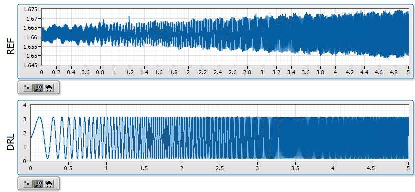
Quick background, I am in a position a signal with a ripple of mV ~ 10 with V 1.6 bias. I'm not interested in DC, only the AC signal but the NOR-9205 has only DC coupling. The application is a circuit where I expect simulations noise past the circuit must be greater than the higher noise frequencies. In the waveforms attached the background plot is the applied signal, and the top graph is the signal arising after that the signal was mostly annihilated. The two waveforms are measured with the NOR-9205.
I am aware that this measure is less than the precision of the NOR-9205, which has a maximum precision of ~ 3 mV in his +/-5V range. However, if I can't at least on the basis of shape which is good enough for me. I'm also now pretty curious that data acquisition is actually to create this
My best idea, is that it is a product of internal multiplexing of the 9205 with the DAC.
The first plot shows the waveform at 20 000 Hz, which is what I expected:
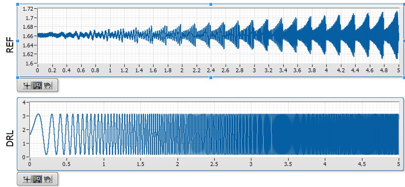
The second shows the waveform at 20 001 Hz, which seems to be modulated with a backup sawtooth:
The waveform looks as expected for 20 000, 20003, 20004, 20005, 20008, 20009, 20010 and Hz 20011. The waveform looks like modulated to 20001, 20002, 20006 and Hz 20007.
Ideally, I would like to understand this problem so that I can configure the measure in a stable way that I can count on the basic shape of the wave. Has anyone seen something similar?
-
NI6602 pulse width measurement: do I have to use an external sample clock?
Hello
In the example .NET 4 "MeasPulseWidthBuf_SmplClk_Cont", it is said in the comments that:
An external sample clock should be used.
Hi mola.
This specific example measures of sample-clocked pulse width. This type of measure is supported only on new hardware such as the X series cards and will not run on the 6602.
Your application that you have linked uses Implicit timing, which means that the signal is using the sample clock. In other words, at the end of each pulse duration which can be measured, the sample is deterministic locked in. So you end up with a table in the buffer of each pulse width which is seen by the meter.
Best regards

Maybe you are looking for
-
HP Envy 15 - 3040nr Sound stopped working
Hello The sound on my hp envy 15-3040nr has just stopped working. I reinstalled the sound drivers, checked to see if the speakers have been disabled in Device Manager and used the tool to troubleshoot the system and security. None of them helped. Its
-
I just bought a new power supply (Corsair CS650M) because someone has suggested that it would be a good replacement power supply for my HP model which is HP Pavilion HPE 1090 t. I need to know if this Corsair works and is compatible with my system,
-
When you try to build an application, I get the following error code: Error 15 took place at the signing of CodeSignAPI.lvlib:Get error String.vi Possible reasons: Error: The time stamp authority URL specified does not point to a valid authority time
-
Is there a risk to delete all empty folders
I'm a "degunking" from my computer. I have removed several unwanted files and delete empty folders. I would like to make a mass delition of empty folders and I wonder if there is a danger in this procedure. The program I have to delete these folde
-
Help. Unable to connect to wireless internet at home
Hello I have a T410 of work that can not connect to my wifi at home. He has worked in the past, but now he's going to connect to my router but will be no internet or say limited connectivity / No.. It is a work computer, so there may be a few firewal