Digital output of 6289 wiring diagram
Hello
I was unable to find a schema for the digital i/o pins of my PXI6289 data acquisition card. I want to know the components of pull-up/pull-down.
Thank you
The f
Jeff-Nickel says:
Hello
Can you tell me if it is out of style-totems? Measurement of source and current wells?
The f
Read the card. It is clear Sourcing and submersion. It seems that it is standard with NI DIO.
Tags: NI Hardware
Similar Questions
-
Digital output of 6289 USB to the function generator
Hi ppl.

I have a DAQ USB-6289 card I use M series to interface with a programmable frequency AD 5932 generator (hope it's not breaking all the rules
 )
)In the datasheet of the http://www.analog.com/en/rfif-components/direct-digital-synthesis-dds/ad5932/products/product.html AD5932
It is the interface series (FSYNC, SCLK, SURLABASEDESDONNEESDUFABRICANTDUBALLAST).
I'm using LabVIEW to generate a digital output and help the Council 6289 to send the signal to the ad5932.
The problem is the following:
(1) I am an engineer in chemistry and new LabVIEW and electronics
(2) I don't understand how the digital signal and the FSYNC SCLK and SURLABASEDESDONNEESDUFABRICANTDUBALLAST are related... Sorry for the very basic question...

Hope that's not too much to ask, but if someone could suggest a tutorial or examples it would be EXTREMELLY appreciated...
Thanks for any input because I'm really stuck on this point.
See you soon
You need to find is the complete technical data on the A/D. Who will explain what each of these pins and the time served. It looks like an SPI interface. OR sell the 8451 for this programming. You can or perhaps are not able to use the 6289. I recommend a search of "SPI" to see if anyone has created a VI.
-
How to secure the wiring of digital output BNC-2090
Hi, I'm working on using the digital output of data acquisition to control the digital DAC input, but I have a problem on how to fix the wiring for the digital output of the DAC. When I plug the cable into the hole, it is vaguely related. Any suggestions on how to fix the wiring are appreciated.
Thanks in advance!
It is a spring terminal.
Try to push in the orange tab with a screwdriver while pushing in the thread. Release tab to release the wire, and it must grab and hold the wire. It may be a case involving Orange instead of push. You should be able to understand.
-
Hello
I am trying to learn labVIEW DAQ and right now I'm trying to understand how to use NI 9474 with labview. NEITHER 9474 is a device with digital outputs. I am attaching a (badly drawn) diagram of how I have my real wired circuit. For some reason, the voltage at the terminals of the resistance is 9v instead what that either the digital output should be when I put assistant daq for 1 sample on request. When I change to continuous samples daq assistant, it reads 4.6v. So I wonder what am I doing wrong and what should my digital output be?
I've attached my vi file, if someone can you please help me understand how to use NI 9474 with labview?
-
Hello
I'm playing with NI 9474 to learn how the outputs digital work with labview. However, I can't even the basic element down. I have a 9v battery connected to the unit and an element of resistance hung on one of the terminals of the device output. So, I just try to get labview to produce a digital output.
However, I get an error when I try to run the labview program. I tried to search my error on the knowledge base, but has been unable to find it. So if someone could help me understand how digital material output works with labview, it would be awesome!
I have attached my diagram!
Thank you
It's pretty basic. If you make an entry, you must specify the values to be written. For digital, values are true/false or 1/0.
-
digital output ARM nodes shipped
I MCB2300 and something more nodes digital output provided (LED 0-7). I have consulted for additional i/o elementary to the instructions here:
http://digital.NI.com/public.nsf/allkb/85DDB6218E7CEEBD8625756D007967CE
However, it only provides additional digital input nodes (even if the pins for these nodes are general-purpose digital input or output).
Is there a method to change these digital ouptut nodes?
Thank you
Hello
The generic MCB2300 target requires the following to access the outputs digital EIO:
- Add EIO of digital input of your project (as in your photo)
- Drop the EIO of digital input on your block diagram
- Click with the right button on the EIO node, and then select 'change to write '.
-
Problem with a digital output in the information of an analog input
Hello
I use a SCXI-1000DC module with a module of the SCXI-1600, SCXI-1531 module and SCXI-1163 module to receive an analog of an accelerometer signal and a digital signal.
I claim that the accelerometer is constantly monitored, and the output is on when I want to, by an impulse that I comand in labview.
I use a rate 25 k and a 12, 5K samples per channel on DAQmx Timing.I notice in DAQmx read, if I put a sample of hight by channel, the output is not there when I want to, and if I put a few samples per channel, I exit when I want to, but the program seems to be slow with the passage of time. I don't know how I can solve this problem!
I'm sorry for my English, and I hope you can help me.
Thank you
Silvia
Hello Silvia,.
If you ask a larger number of samples, the labview diagram will stay longer in the DAQmx Read function, so the while loop runs slowly, and the digital output is updated less often.
I suggest that you use 2 separate while loops: one for the analog input and the other for digital output, so that each loop might run at a different speed.
Best regards
-
PCIe-7842R (series R FPGA) digital output does not work properly
Greetings,
I'm having some problem show TTL the correct voltage with my PCIe-7842R FPGA board.
The block diagram of my code FPGA LV Moose appears in "analog - digital .png '. The idea was to convert an analog input (decimal value) to a binary code and 16-bit output by 16 DIO ports. I use the connection block SCB-68 has as the terminal and trendy on the FPGA 1 connector RDIO with SHC68-68-RDIO shielded cable.
The compiled code ok. But during the test, I noticed that some ports has no output TTL levels correctly. For example, for input 1000 decimal, I would expect binary code 0000001111101000. However, some ports (DIO #6, #7, #9, etc.), which are supposed to ~3.3V (1 digital) high TTL output, output actually 0.8V. I have attached the result measured in 'exit digital test.png '.
To ensure that the question was not because of the code of the LV, I did some more tests on DIO #6 with a simple example (simple digital output.png). The output was ~ 1V this time at the digital 1.
It's really confusing because of the digital Edition is supposed to be simple. I used the same FPGA card for controlling roller shutters with TTL signals before and it worked fine.
Does anyone have similar problems? Any suggestions are greatly appreciated.
iron_curtain wrote:
DIOs are connected to a controller digital galvo Cambridge Tech. But I measured the voltage at the terminals of the connector block.
If you unplug the controller galvo DIOs, do they look good (have the right voltages). Do you know how many of these entries to the need for controller? I think you hit the limit the total current available for EID within the Council.
-
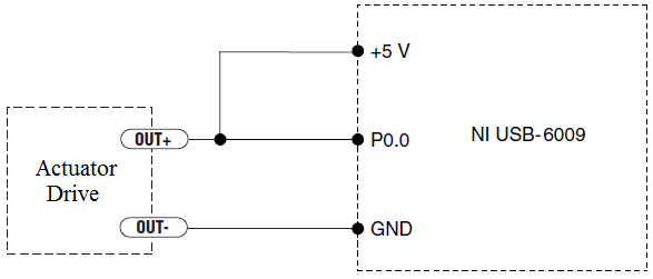
How to measure the digital output of the linear actuator on USB-6009?
Hello
I am a new user of Labview and need help to measure a digital input signal.
I have an actuator Bimba Original line electric with a motor continuous integrated with encoder, drive and the controller. The drive has a programmable digital output that I put as a tachometer output that emits pulses of square wave 100 per turn of the engine. I put the engine to make a total of 56 rev in 22 dry. I want to measure the speed of motor rotation labview real-time and synchronize it with a few other analog input signals. I wired the actuator for the USB-6009 case as shown below.
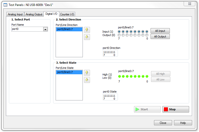
I opened the test i/o digital USB-6009 Panel and fix all the lines of port 0 as inputs. However, when I click on start and run the actuator, p0.0 led flashes, as indicated below.
Shouldn't the led blink in response to revolutions of engines?
I want basically to collect the drive pulse signals and convert them in rpm on labview.
ahsan2 wrote:
I have it wired correctly?
It would help if you do not attach the HIGH signal. Remove the + 5V in the circuit.
-
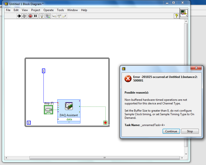
digital output remain on inout end is off
Hello
I've been rattleing my head on this for the last two days with no luck.
What I try to do is the following:
Send a signal in a NI9421 Module, when the module receives this signal, it should exit on the NI 9472. These 2 steps I've completed and work however is the next part whicc I have problems with.
When the input signal is removed from NI9421 I would kepp receives a signal from the NI9472 for a period which can be easily adjusted.
I tried to highlight delays / waits (FOR loops behave as counters), while loops etc, but this doesis delays the time between entry Street to before the output turns on. for example. If I put in a 5 second delay, entry must be closed 5 seconds before the output turns on, and output will then stay on for another 5 dry.
Any help is very appreciated.
Thank you
John
Hi John,.
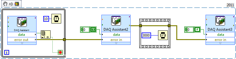
Take a look at the sample code below along with a description, if all goes well it will help you get started.
The while loop in the early polls pin digital input and a real wait to exit the loop and enter Assistant2 DAQ. The while loop in it has a wait of 10ms. This is to avoid it running fast and hogging all you time CPU. Since the output of the DAQ Assistant, in the while loop is a table, table VI Index allows to get a value that is wired in the loop condition.
The yellow lines used throughout of are lines of error and these can be very useful in LabVIEW to synchronize / order parts of your code. Following the order of the execution rule of in that the DAQ Assistant2 will not begin until all loop has finished running.
I then used a flat sequence order within 3 seconds (with error lines) between the second DAQ Assistant and the third that turns off the digital output.
Hope this is clear and useful
-
Control the Boolean commands and generate a corresponding digital output
Hi all
I'm working on a project of activation of the electrode, here, I thought that how could I order an electrode in a time and generate a digital output of it accordingly. I want to replace it with each electrode with a LED on the front panel and generate a numerical value to each LED on the block diagram.
If it can be divided into two parts
1 control the Boolean outputs
Here, my goal is that if I have 5 leds that are used as a Boolean control, must be ordered so that only one of them lights up at the same time and the rest goes off.
I mean for example if #3 was turned on and that the user pressed the #3 #2 should be turned off and only #2 lights.
2. generate the corresponding numerical value
Depending on the position of the LEDs I want to generate a corresponding numerical value, as previously released 3 coming and exit 2 then comes when the second LED illuminates.I ask all participants to this group to help me with this.
Concerning
Why don't you use the radio button control? You can replace the boxes if you want the buttons.
-
Maximum speed of digital output of the DAQ 6009
Hi all
I'm trying to generate a clock the digital output on my USB DAQ 6009 puse. The maximum frequency, that I was able to produce was 0.5 kHz, but I would like to generate at least 1 kHz. I HT wired port0/$line0 of the OID of data acquisition to the data acquisition ai0 and attempted to read the output via the input of an analog of the same device. I have attached the programs here. Don't know if it's right. You can help. Thanks in advance.
150 s/s is the maximum rate of the analog output. The 48kS/s is the maximum rate of the analog input. Read a little more closely.
This unit will not do what you want. I recommend putting the hand of your representative local of NOR and discuss your needs with them. They should be able to set you up.
-
audio output: optical digital output port (no sound!) macbook pro retina 15 mid 2015
My new recently Mbpr 15 inch has suddenly lost its sound, I went through the process of the toothpick etc but nothing. It worked perfectly fine earlier today, but I put in a mini jack into the headphone port and after to achieve 30 minutes later and taking the cable to THE that I had not his, then I had the red light coming out of the helmet but now its does not come in red and in the sound settings in system preferences its impasse on "optical digital output Port.
I now have to wait a week to wait until I can get seen at my apple store closet, I coming projects upward and in the middle of deadline and really using this Mbp to work, I literally only had a TI surly less than two months, I shouldn't have any problems. So if anyone knows anything I would appreciate it a lot! I need help to get this resolution as soon as possible! the last post I saw this was in 2006-2012 no new thread on this recently!
Thank you!
Jasonwaterz wrote:
I then had the red light coming out of the helmet but now its does not come in red and in the sound settings in system preferences its impasse on "optical digital output Port.
Try resetting the NVRAM/PRAM http://support.apple.com/kb/ht1379 memory
-
hpe - 337C ww583aar wiring diagram
USB ports before damaging the USB devices. Suspect MB of wiring to the USB ports on the front panel, but you don't know where the riders should go.
MB has 6 positions labeled header - JUSB1, 2,3,4,5,6. JUSB1 & 2 seem to accept the connectors 1 X 5 or 2 X 5. JUSB3-6 accepts only 1 X 5 connectors.
Two front jumper cables have connectors 1 X 5. Pin 1 = red, 2 = white, 3 = green, 4 = black, 5 = white/matched.
Currently - the front panel low port USB is rider for JUSB1 (pine 1,3,5,7) & the USB ports on the front top of the page are related to JUSB2.
Sorry, but there is no wiring diagram. If the cable has a connector 1 x 5, the best locations to plug in the USB headers 3-6 East. If the cable has a connector 2 x 5, the best locations to plug in the East headers USB 1 & 2.
If you have any other questions, feel free to ask.
Please click the White Star of KUDOS to show your appreciation
-
Realtek integrated sound card is stuck in digital output
I can't get this thing off the digital output mode. Now I have no sound because all analog ports do not work. Telling me that nothing is plugged. I can't reset the analog speaker because it is grayed in Vista. This problem seems to be very common with computers using Realtek and Vista, just do a google search and see for yourself.
I have a feeling it has software problem between Vista and Realtek. But I really think Realtek is just terrible to began with and should not be put in any period of the computer. If I can't get this thing works here tomorrow I will get a good real map.
Message edited by hn333 on 09/04/2009 21:02I had very similar problems and finally managed to solve it.
Something seems to be borked with drivers realtek about automatic jack detection.
After attempting to use the method described here (easier if you can) http://freeweelee.wordpress.com/2008/12/09/vista-and-realtek-front-panel-audio-not-working-solution/, I discovered that I was completely unable to cut jack detection in audio Manager Realtek (no folder icon).
For those of you who (like me) have no icon file, I managed to find another way to disable the detection of jack.
Using the registry editor, find all instances of ForceDisableJD and change the value from 00 to FF.
After making sure that I got all of them, I was able to reboot and everything works fine now.
Maybe you are looking for
-
Hello I received a 2 TB Stor.E TV HD +.I lost the remote, so I can't use it. I call the help number and they told me it is not possible to obtain a further distance of toshiba. So my question: do have someone at - it had the same problem solved?Is th
-
AYUDA POR FAVOR (ERROR IN THE DELIVERY)
Buenas noches, esto are what esta sucediendo con mi Skype chat is supone el contacto blog again when y estamos ambos estos messages connected not deben häberle come pero no pasan los dias y no do; Alguien me can give a response! invite me!
-
What is the diagnostic tool Microsoft Genuine?
original title: THIS WHO IS MGADIA? WHAT IS MGADIA?
-
Canon MX922: Why won't my scanner scan color photos?
Hello, my Canon MX922 produced copies of any color, but when I scan a color photo, the results of the analysis of a color photo are only in black & white, even when I push the Start button 'color' to scan. However, the scanner will produce color doc
-
I don't know how to get all my music (including Itunes) in my Windows Media Player library. I'm so confused. Can someone please help me get this straightened out?