NI 9474 digital output errors
Hello
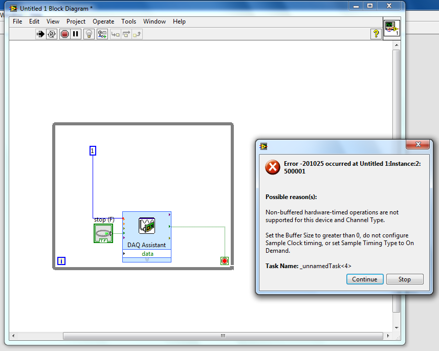
I'm playing with NI 9474 to learn how the outputs digital work with labview. However, I can't even the basic element down. I have a 9v battery connected to the unit and an element of resistance hung on one of the terminals of the device output. So, I just try to get labview to produce a digital output.
However, I get an error when I try to run the labview program. I tried to search my error on the knowledge base, but has been unable to find it. So if someone could help me understand how digital material output works with labview, it would be awesome!
I have attached my diagram!
Thank you
It's pretty basic. If you make an entry, you must specify the values to be written. For digital, values are true/false or 1/0.
Tags: NI Software
Similar Questions
-
Hello
I am trying to learn labVIEW DAQ and right now I'm trying to understand how to use NI 9474 with labview. NEITHER 9474 is a device with digital outputs. I am attaching a (badly drawn) diagram of how I have my real wired circuit. For some reason, the voltage at the terminals of the resistance is 9v instead what that either the digital output should be when I put assistant daq for 1 sample on request. When I change to continuous samples daq assistant, it reads 4.6v. So I wonder what am I doing wrong and what should my digital output be?
I've attached my vi file, if someone can you please help me understand how to use NI 9474 with labview?
-
NI-DAQ-200288 digital output error
Hi all
I am using Matlab control PCI-6534. In the code, I try to write not Npulse (= 3). Pulse. Data of the pulse are of size 1 X 1e5. When I try to write in the mode of generation of finite samples it generates error-200288 when you write data pulse 3rd time. 1 twice, it gives no error.
The flow of code below is 1. Open 32-bit channel to write digital data to the 10 MHz clock.
2. put sample over genration and disabel regeneration.
3 write first pulse data to buffer.
4. start the task
5 enter the number of data pulse Npulse-1 immediately
6. wait until the task is done and stop the task
CLC;
inputDATA = uint32 (100 * randn(1,1e5));
NPulse = 3;
rate = 1e7; % 10 MHzIf (libisloaded ('myni') ~ = 1).
[notfound warnings] = loadlibrary ('nicaiu.dll', 'C:\Program Files\National Instruments\NI-DAQ\DAQmx ANSI C Dev\include\NIDAQmx.h','alias','myni');
end
taskh = libpointer('voidPtrPtr',0);
DOtaskhandle = taskh;
[errCode, taskName, DOtaskhandle] = calllib ('myni', 'DAQmxCreateTask', ", DOtaskhandle);
DOtaskhandle.setdatatype ('voidPtrPtr');DAQmx_Val_ChanForAllLines = int32 (1);
DAQmx_Val_Rising = int32 (10280);
DAQmx_Val_GroupByChannel = uint32 (0);DAQmx_Val_FiniteSamps = int32 (10178);
DAQmx_Val_GroupByChannel = uint32 (0);
DAQmx_Val_DoNotAllowRegen = int32 (10158);
numSampsPerChannelWritten = libpointer('int32Ptr',0);
reserved = libpointer ('uint32Ptr', []);
data2 = libpointer ('uint32Ptr', inputDATA);
sampsPerChanToWrite = uint64 (numel (inputDATA));
inDataLen = uint32 (numel (inputDATA));
sperchan = uint32 (inDataLen);[errCode, lineNames, nameoflines] = calllib ('myni', 'DAQmxCreateDOChan', DOtaskhandle, [' Dev1/port3 Dev1/port1, port2/Dev1, Dev1/port0], ", DAQmx_Val_ChanForAllLines);
[errCode, clockType] is calllib('myni','DAQmxCfgSampClkTiming',DOtaskhandle,'OnboardClock',rate,DAQmx_Val_Rising,DAQmx_Val_FiniteSamps,sampsPerChanToWrite);
If (errCode ~ = 0)
errMessage = "Error during clock setting";
calllib ('myni', 'DAQmxStopTask', DOtaskhandle);
calllib ('myni', 'DAQmxClearTask', DOtaskhandle);
return;
end
[errCode] is calllib ('myni', 'DAQmxSetWriteRegenMode', DOtaskhandle, DAQmx_Val_DoNotAllowRegen);.[errCode, writeArray, numSampsPerChan, zz] = calllib ('myni', 'DAQmxWriteDigitalU32', DOtaskhandle, sperchan, 0, double (10), DAQmx_Val_GroupByChannel, data2, numSampsPerChannelWritten, reserved);
If (errCode ~ = 0)
errMessage = "Error when writing the data of Stimulation" 1;
calllib ('myni', 'DAQmxStopTask', DOtaskhandle);
calllib ('myni', 'DAQmxClearTask', DOtaskhandle);
DISP (errMessage);
return;
end[errCode] = calllib ('myni', 'DAQmxStartTask', DOtaskhandle);
if(errCode~=0)
errMessage is ('error in startup DAQmx task');.
calllib ('myni', 'DAQmxStopTask', DOtaskhandle);
calllib ('myni', 'DAQmxClearTask', DOtaskhandle);
DISP (errMessage);
return;
end
for i = 1:NPulse - 1
[errCode, writeArray, numSampsPerChan, zz] = calllib ('myni', 'DAQmxWriteDigitalU32', DOtaskhandle, sperchan, 0, double (10), DAQmx_Val_GroupByChannel, data2, numSampsPerChannelWritten, reserved);
% If (errCode ~ = 0)
% errMessage = "Error when writing the data of Stimulation";
% calllib ('myni', 'DAQmxStopTask', DOtaskhandle);
% calllib ('myni', 'DAQmxClearTask', DOtaskhandle);
disp (errMessage);
% return;
end %
endIstaskDone = libpointer ('voidPtr', logical (0));
[A11 A21 A31] is calllib ('myni', 'DAQmxIsTaskDone', DOtaskhandle, IstaskDone);.while(A31==false)
[A11 A21 A31] is calllib ('myni', 'DAQmxIsTaskDone', DOtaskhandle, IstaskDone);.
endcalllib ('myni', 'DAQmxStopTask', DOtaskhandle);
calllib ('myni', 'DAQmxClearTask', DOtaskhandle);Can anyone help me please with this code. Is there some step I'm missing or not setting any parameter not?
Thank you
Vani
Take a look at this:
Why do I get error-200288?
http://digital.NI.com/public.nsf/allkb/BFCE83133C0ECAD786256E6000814B68?OpenDocument
Using traditional DAQ or DAQmx?
-
clock calendar - digital output
Hi all!
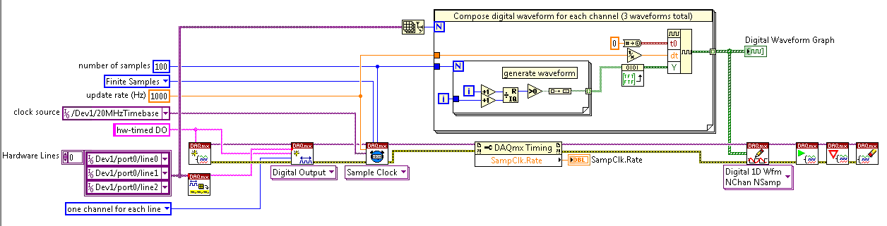
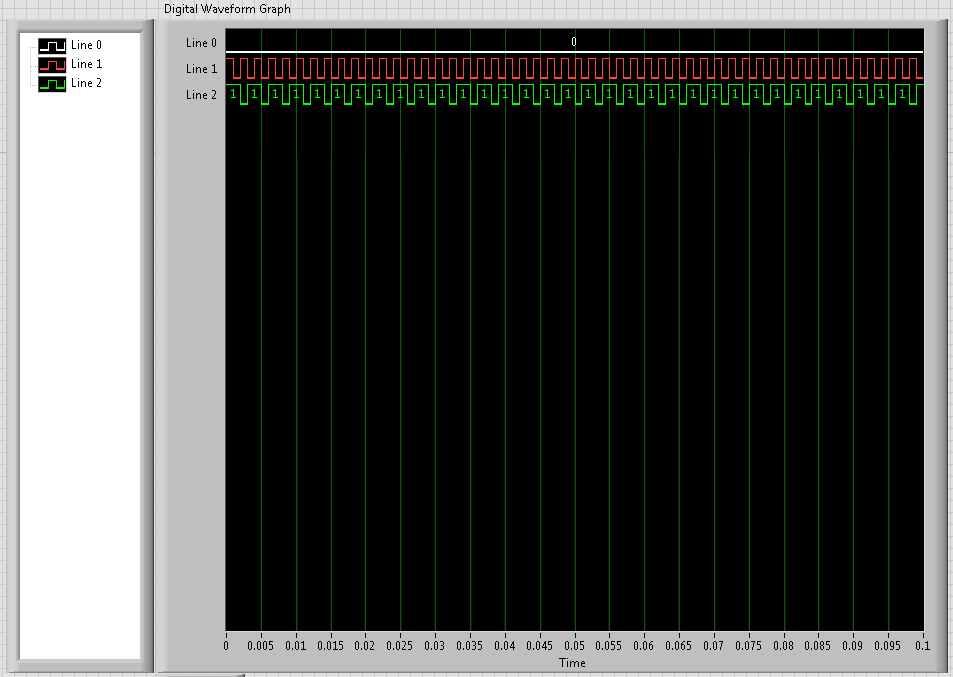
I need timing equipment impliment on a few digital output lines. That's what I have so far:
I didn't get an oscilloscope for her yet, but I'm fairly certain that it works. Please note that in this example, I use a PCI-6115. I have 2 questions:
(1) make what I do look reasonable at a quick glance?
(2) I'm kinda mistified by the entry of clock source to the example of the clock function. The analysis that I read just still confuses me. I understand that the clock is what dictates the sequence of material. I do not understand how to choose the appropriate clock source correctly. More specifically, in the above example, I've only had the program work when I chose "20MHzTimebase". What is c? Why this work?
When I try to select ' Dev1 / / SampleClock ", I get the following error:"attempted to perform a route when the source and destination are the same point."
When I try to select "Dev1/PFI0" or "RTSI0/DEV1", I get a timeout error in the wait_until_done.vi--> it does not appear that the waveforms are executed.
That means the PFI and RTSI acronym for, and why they appear as options when you select a source of the clock? Furthermore, why have they not worked as a clock source?
I would be very grateful to anyone who could clear things for me a little. Thank you!
Have you read the http://digital.ni.com/manuals.nsf/websearch/01C075FB9478F94A8625786A007435BA? manual The definition of PF and RTSI are here. They are designed using external clock signals. You have the choice of using the internal clocks of analog output (20 MHz) or external clocks. If you do not connect the RTSI bus or PF what, whether you have no clock so no data will be output. Selection of as source does not work because it is not a source. You provide a source for it.
-
How to quit smoking all the void s vi before resetting digital outputs and then closing
I have a project that contains a main VI called home screen that calls many different sub vi. I am monitoring for a press of physical button by a digital input with a DAQ Assistant on the main VI and in this case I want my program to abandon all of its VI running and reset all the digital outputs before the closure of Labview. No idea how I would go all this?
I have attatched the basic model of what I do.
Joelspider33 wrote:
The problem is more to do with some of my money that VI running a DAQ Assistant using the same digital lines like the ones I'm wanting to reset and causing it to throw up an error message.
This is why you must set the DIO AFTER all subVIs are arrested. And to do this, you must send messages to these subVIs telling them to stop. If done correctly, it is a very quick process.
-
digital output microsecond LED timer
Hey all,.
I'm doing a table of 10 LEDs in a row to form an analog timer to use to characterize the delay of the shutter on a digital SLR. We'll first stage shutter lag on the camera using a method different and well set the delay of the shutter for interior<1ms. i="" am="" trying="" to="" use="" labview="" alongside="" a="" ni="" usb="" 6251="" using="" an="" sc-2345="" for="" access="" to="" the="" digital="" outputs.="" im="" using="" a="" timed="" structure="" and="" a="" timed="" loop="" to="" ensure="" the="" timing="" between="" each="" led="" turning="" on="" corresponds="" to="" an="" actual="" time.="" however,="" i="" am="" not="" getting="" the="" results="" i="" thought="" i="" would.="" the="" timing="" does="" not="" seem="" to="" be="" what="" i="" thought="" it="" would="" be="" and="" i="" can="" not="" get="" the="" timed="" loop="" to="" work="" with="" all="" the="" channels="" at="" the="" desired="" frequency="" which="" would="" idealy="" be="" as="" high="" as="" possible.="" could="" someone="" take="" a="" look="" at="" my="" code="" and="" provide="" me="" with="" some="" insight="" where="" i="" may="" be="" getting="" issues?="" i="" apologize="" if="" i="" am="" overlooking="" important="" information="" that="" may="" be="" needed="" to="" help="" solve="">
~ Aaron
I have no DAQmx I can't be sure. I think that the 6251 has a maximum rate of 1 MHz in order to try to set the rate to 20 MHz should generate an error. For the purposes of test on the rate 1 Hz bit or less. Then you should be able to see the LEDs as turning on and off.
You may also need to set the number of samples to the size of the array. Referring to the size of the array fed to Scripture DAQmx, not the table on the front panel. With the number of samples set to 1, I would expect that he wrote that the first element of the array that is equal to zero. That does not produce a very interesting performance: he lets just all lights off the coast!
Lynn
-
Digital output with timer (Simulation)
Hello everyone, I just found out how LabVIEW program a week ago. I try to do a simulation of digital output by LabVIEW (my attachment). In this simulation, I have a slider as an input (0-10 V), two digital controls (upper limit and lower limit), a waveform graph draw these 3 evaluates and two Boolean LED (P0.0 and P0.1) as indicator. In this simulation, you can fill any number (between 0 and 10) in numerical order as a limit for your entry cursor. If the entrance of a cursor exceeds these upper and lower limit, then the Boolean LED lights, P0.0 so exceeds the upper limit, and if P0.1 exceeds the lower limit. The problem is that I do not know how the timer for those Boolean LED. As an example:
(1) make an entry of cursor,
(2) if entry (1) exceeds the upper limit, P0.0 lights for 5 seconds, then turn to during 10 second.
(3) if only 10 seconds, you change the entry back to normal (between high and low limit) then P0.0 will stay turn of until the cursor entry exceeds the upper limit again,.
(4) If, in this second 10 you has not changed the entry (the stay exceeds the upper limit) then P0.0 repeats the process (2) until you the entrance to cursor back to normal.
(Same process for entries exceed the lower limit).
Can you help me do this timer? Thank you

Concerning
Juventom
Hello
If you don t mind I would just give you some advise to your code. To determine the data stream you can also use only the error wire connected to the loop. So Don t you really need, it's beter not not to use variables. For your solution, you can use something similar to what I tried for the upper limit in your program. It is added as an image.
Hope it helps
-
USB-6211 - digital output not supported?
Hi all
I can't use the USB6211 device port... I use daqmx with Delphi7 API functions.
First of all, I tried this:
DAQmxCreateTask('', @TaskDO);
DAQmxCreateDOChan (TaskDO, PChar('Dev1/port0'), ", DAQmx_Val_ChanForAllLines);
DAQmxWriteDigitalU8 (TaskDO, 1, 1, 1, DAQmx_Val_GroupByChannel, $FF, @written, nil);I had an error in the DAQmxWriteDigitalU8:-200012 (= digital output not supported). (???)
OK, I tried to disable autostart option based on DAQmxWriteDigitalU8 and insert a 'manual' start in the code:
DAQmxCreateTask('', @TaskDO);
DAQmxCreateDOChan (TaskDO, PChar('Dev1/port0'), ", DAQmx_Val_ChanForAllLines);
DAQmxStartTask (TaskDO);
DAQmxWriteDigitalU8 (TaskDO, 1, 0, 1, DAQmx_Val_GroupByChannel, $FF, @written, nil);
DAQmxStopTask (TaskDO);Now, I got the same error in DAQmxStartTask:-200012 (Digital Output not supported, once again). (?????)
I don't understand.. 'Digital output not supported "? USB-6211 has 4 lines! What is the problem?
I want to just turn on and off the lines from code...
-Cs George-
Well, finally I figured out...

Here is the solution:
DAQmxCreateTask('', @TaskDO);
DAQmxCreateDOChan (TaskDO, PChar('Dev1/port1'), ", DAQmx_Val_ChanForAllLines);
DAQmxWriteDigitalU8 (TaskDO, 1, @dummy, 1, DAQmx_Val_GroupByChannel, @bitmask, @written, nil);Digital output lines are on port1! Corrected parameter.
And the part of the interface of DAQmxWriteDigitalU8 had to be changed (in nidaqmx.pas).
I don't know why, but the AutoStart (dummy) parameter in the DAQmxWriteDigitalU8 function is ignored: function always starts task automatically, regardless of the value of autostart. But this isn't a problem for me.-Cs George-
-
digital output remain on inout end is off
Hello
I've been rattleing my head on this for the last two days with no luck.
What I try to do is the following:
Send a signal in a NI9421 Module, when the module receives this signal, it should exit on the NI 9472. These 2 steps I've completed and work however is the next part whicc I have problems with.
When the input signal is removed from NI9421 I would kepp receives a signal from the NI9472 for a period which can be easily adjusted.
I tried to highlight delays / waits (FOR loops behave as counters), while loops etc, but this doesis delays the time between entry Street to before the output turns on. for example. If I put in a 5 second delay, entry must be closed 5 seconds before the output turns on, and output will then stay on for another 5 dry.
Any help is very appreciated.
Thank you
John
Hi John,.
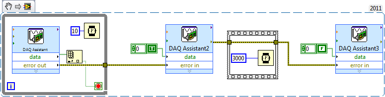
Take a look at the sample code below along with a description, if all goes well it will help you get started.
The while loop in the early polls pin digital input and a real wait to exit the loop and enter Assistant2 DAQ. The while loop in it has a wait of 10ms. This is to avoid it running fast and hogging all you time CPU. Since the output of the DAQ Assistant, in the while loop is a table, table VI Index allows to get a value that is wired in the loop condition.
The yellow lines used throughout of are lines of error and these can be very useful in LabVIEW to synchronize / order parts of your code. Following the order of the execution rule of in that the DAQ Assistant2 will not begin until all loop has finished running.
I then used a flat sequence order within 3 seconds (with error lines) between the second DAQ Assistant and the third that turns off the digital output.
Hope this is clear and useful
-
Original title: unplugged... HDMI?
So I have a laptop Vaio of microsoft. The microphone that was integrated into the laptop was working fine until recently. No, I talked through my laptop was able to hear me except through Skype. I search through my laptop and say something like in the playback than digital output device or interface (HDMI) was disconnected. I know very well that I unplugged it. Can someone please?
Hello
1 did you change on your computer before this problem?
2. you receive an error message?
3. What is the exact make and model of your laptop?
4. are you able to record from Microphone?
5. which version of the operating system is installed on your computer?
What version of the operating system Windows am I running?
http://Windows.Microsoft.com/en-us/Windows7/help/which-version-of-the-Windows-operating-system-am-i-running
Make sure that the Microphone settings are set up correctly.
a. right click on the Volume icon in the notification area.
b. go to recorders and right click on the empty area.
c. Select Show disconnected devices and show disabled devices.
d. right click Microphone, and select activate.
e. Microphone right click and select Properties.
f. Select the option use this device for the use of the device falling down.
g. go to the levels tab and move the slider to the maximum level.
h. click on apply and OK.
See also:
Tips for solving common audio problems
http://Windows.Microsoft.com/en-in/Windows7/tips-for-fixing-common-sound-problems -
6534 PCI for digital output finished generates a continuous output
Hello
I use 6534 PCI for my application, where I generate a digital output, a model finished variable length in a continuous loop. the code runs without error, but I'm not able to justify the behavior of the map. I intend to use the code inside the while loop as a Subvi and if I change the 'command' at the entrance table during each call to the Subvi, the output should vary according to the directives of the entry of the 1 d array.
But this is not the case, the loop displays the previous value that has been given to Scripture DAQmx. If the control panel is changed the output instantly does not change. It takes a while before the actual output changes. The length of the array command I give is also 88 & 133. When I realize that the output is wrong, I disable the DAQmx write vi by a structure of the case, I would expect an error that the output buffer is empty, but rather the old value is generated whenever the start Daqmx vi task is exectuted without.
My tax any problem is that the output buffer is not get replaced with the new value, but I'm specifyng the size of buffer, performing a registration every time and start the task, waiting until the task is done and the task stop. Each stop & writing should delete and empty the buffer, but I did not understad what goes wrong.
Also, I thought that maybe that orders are put in queue up in the output buffer, acual generation is not as fast as the call of the DAQmx write & start, but if that's the case then even if I stop the vi the generation should be until the buffer is empty, but that doent happen VI, break breaks of generation. the number of iterations is equal to the generated models. If anyone can help as to what could be the problem? fi
nd code attached below.
Hello
If I understand the problem you are experiencing, then the reason for the typical behavior when you run the VI, it is that you are not clearing the DAQmx task whenever you intend to go for a fresh DIO write. You stop just the DAQmx task that seems however to clear the buffer on board space.
With this post, I am enclosing a VI of the sample that should work according to your expected behavior. You can even call this VI as a Subvi and can use it to update the DIO port with a digital model of variable length fees. Another fact that I would like to point out, is that, once you have initalised one table, it is not possible to reduce the length of the array. You can only increase by adding new elements. According to your needs given that the digital model that needs to be updated will be of variable length, each time you cll the Subvi, you must create a freash of appropriate length and feed it as input to the Sub - VI. Inside the Subvi, according to the length of this array of entry appropriate buffer space is allocated.
Do trust this solution help solve you the problem, otherwise do not hesitate to go back.
Best regards,
Sagar G yapi | Application engineer | National Instruments - India
-
audio output: optical digital output port (no sound!) macbook pro retina 15 mid 2015
My new recently Mbpr 15 inch has suddenly lost its sound, I went through the process of the toothpick etc but nothing. It worked perfectly fine earlier today, but I put in a mini jack into the headphone port and after to achieve 30 minutes later and taking the cable to THE that I had not his, then I had the red light coming out of the helmet but now its does not come in red and in the sound settings in system preferences its impasse on "optical digital output Port.
I now have to wait a week to wait until I can get seen at my apple store closet, I coming projects upward and in the middle of deadline and really using this Mbp to work, I literally only had a TI surly less than two months, I shouldn't have any problems. So if anyone knows anything I would appreciate it a lot! I need help to get this resolution as soon as possible! the last post I saw this was in 2006-2012 no new thread on this recently!
Thank you!
Jasonwaterz wrote:
I then had the red light coming out of the helmet but now its does not come in red and in the sound settings in system preferences its impasse on "optical digital output Port.
Try resetting the NVRAM/PRAM http://support.apple.com/kb/ht1379 memory
-
Realtek integrated sound card is stuck in digital output
I can't get this thing off the digital output mode. Now I have no sound because all analog ports do not work. Telling me that nothing is plugged. I can't reset the analog speaker because it is grayed in Vista. This problem seems to be very common with computers using Realtek and Vista, just do a google search and see for yourself.
I have a feeling it has software problem between Vista and Realtek. But I really think Realtek is just terrible to began with and should not be put in any period of the computer. If I can't get this thing works here tomorrow I will get a good real map.
Message edited by hn333 on 09/04/2009 21:02I had very similar problems and finally managed to solve it.
Something seems to be borked with drivers realtek about automatic jack detection.
After attempting to use the method described here (easier if you can) http://freeweelee.wordpress.com/2008/12/09/vista-and-realtek-front-panel-audio-not-working-solution/, I discovered that I was completely unable to cut jack detection in audio Manager Realtek (no folder icon).
For those of you who (like me) have no icon file, I managed to find another way to disable the detection of jack.
Using the registry editor, find all instances of ForceDisableJD and change the value from 00 to FF.
After making sure that I got all of them, I was able to reboot and everything works fine now.
-
No digital output on a Satellite P200
I just bought a Satellite P200 and am trying to put it to the test. Today I tried recording on a digital audio recorder (Edirol R-4) connected to the output digital output jack but can get no signal. I can get a signal from the analog headphone jack.
I have no problem with digital recording of my desktop PC which has an installed Sound Blaster card so it doesn't seem to be an incompatibility or a problem with the connecting cable.
I tried to set the default output to digital mode in the setup of REALtek but no difference.
Any suggestions gratefully received.
David
Anyone else had this problem?
David
-
Synchronization of analog and digital output with the external sample clock
Hello
First of all sorry for my English, I will try to explain what I want to do.
I want my PCIe-6321 to send two custom signals (modification sawtooths) on a mirror controller. I would also like to generate output with my card at the beginning of each tooth of saw. Everything must be synchronized with an external k-clock signal of 100 kHz. The idea is that whenever the PCI receives a trigger to external clock, it sends two analog output voltages and when he received 1024 clock ticks it will also send a pic of triggering TTL. What I do is first prepare the map and after that in a loop sending and modifing the output values of the two signals and at the same time send a digital signal Boolean in each arch, so when's done it 1024 iterations of the loop I send an event to the digital port. Attached you can see.
The problem is that I don't know how to synchronize both. Can I use the sample clock just to the analog output? I can use sample for the two outputs clock, or do I need to use the output of the meter? If don't know how to use it here.
If I do nothing else bad/wrong, I would be grateful for feedback.
Thanks in advance,
PabloI don't know how but I find the solution. I'm generating more than a positive value (as I was triggered maybe very fast the oscilloscope has been absent there). If I put the sample clock of digital output to use the sampling/ao/Dev1 clock that it doesn't, but if I put to use the same source as the OD (terminal where my external clock is connected), but the trigger to start the DO to be Dev1/ao/StartTrigger this works. I don't really know why, but it does.
Thank you for your patience and your help. I put here the final code.
Maybe you are looking for
-
I need to know if I'm in 32 or 64 bit Firefox, how?
I'm looking at programs that support 32 bit, not 64 in Firefox but can't find what I use.
-
Satellite U300 - cannot get sound card running Windows XP Home edition
Hi all I installed Windows XP Home edition on my U300 after playing with nlite nd the sata raid drivers.I installed all think them, but my card doesn't work his and my webcam also. I m now 3 days on it and t can find a solution. Please if someone els
-
I have an Acer Aspire 5742-6638 running on Core i5 - 480 M under Windows 7 64-bit. I'm trying to clone my hard drive for an SSD. Tried with the help of Paragon Drive Copy and EaseUS Todo Backup. Both said cloned successfully, but the two could not
-
New model: HP Envy 15 t Upgrade HD SSD or mSATA SSD?
Hi all I read several threads on the upgrade of the disk for SSD and it seems that everyone else has managed to do. My question is, is there an advantage to upgrade to an SSD HARD drive or simply add in mSATA SSD? I currently have a network drive t
-
I'm watching a film on BBC iPlayer.It is downloaded as a high quality video.After 20 minutes, the phone has heated a lot and read started badly stuttering.As in the program is very bad with it stop for 2-3 seconds every 10-15 seconds. Known issue?