DMA with FIFO data acquisition
Hi all
I would like to ask you a favor to get some help to understand FIFO. I have attached the files here and simply the target more basic FIFO of host data transfer. I put the required number of elements to 4095, I understand the depth of the FIFO on FPGA. The sampling rate in FPGA is 10 kHz. The loop on read host rate is 10 ms. The depth in the host FIFO.configure is 10000, which I think is the number of items in the part of host of the FIFO DMA memory. So I guess that the total thickness of the FIFO is 14095 elements. I put the points of reading in each iteration to 2000 points. However no matter how to change the combination and number of points to read, the program performs an iteration and then displays a different error message.
Can someone please help me understand how to calculate each parameter and to optimize it, if the sampling frequency I want on FPGA is data of 10 kHz I16? Thank you very much. I appreciate your help!
Best,
Charles
I have attached all the files here, which is very similar to the example on ni.com
Charles Hey,
Regarding the second question, it's what I wanted. I'm not 100% sure how the constraint point converts a dbl in unsigned int, so it would be good to use a node of conversion and to probe this value, to ensure that you get the value you expect.
As for the second question, I told you that you should wiring in a contstant-1 in the field timeout of your fifo method on the RT VI and VI FPGA read.
Thank you
Tags: NI Software
Similar Questions
-
Creation of a current 64kHz with a data acquisition signal?
I'll make a few measures of impedance and need a device to produce a signal of low current(0,1mA) 64kHz and to pick up 2 differential tensions. Are there materials Multifunction DAQ, which produces a constant current or can I use a device with an output voltage and a voltage converter?
Adam
I'm not aware of a source of current to 100µA at 64kHz metrologic...
I would try this:
Why not just apply an alternating voltage and current measurement and the voltages?
Another way to apply a rectangular waveform of 100µA: place a REF200 (100µA 2 references) in a diode bridge and apply a 64kHz squares

-
Hi all
I have two functional screw a loop a set of read and write tasks with device 1 (NI USB-6008). The second loop a set of writing with device 2 (another NI USB-6008) tasks. 2 VI has a massively slower than VI 1 time scale, which means that it must run in a separate loop. Otherwise, VI 2 was created by copying and modifying 1 VI and variable names actions with him (though not, for example, global variables). The two screws are meant to run at the same time on the same PC.
However, if VI 1 is running at the same time as VI 2, any read operations or in writing to 1 VI 1 device are executed - but the VISA read and write operations to a serial device work. When VI 2, all VI 1 functions work fine.
Although I configured channels for tasks using the GUI DAQmx, I execute tasks using reading DAQmx write commands and have correctly defined the task 'create' and 'stop the task' live out the beginning and the end of my loop, respectively.
Does anyone have suggestions for what could be the cause? My thoughts so far:
a. maybe it's some conflicts in the names of variables in memory between the two screws?
b. LabVIEW for some reason any cannot read and write two devices on two separate screws?
should c. I avoid to use DAQmx to configure these tasks (a sort of memory)?
I know I can make it work if I have all together in a single massive VI, but for my application, it is much easier and better to do them in two separate screws.
Thank you in advance for your help!
In case anyone wondered, I found the solution:
When I copied the original code for a new VI, it turns out that the structures of loop timed in the new VI had the same object name in the delivery structure of LabVIEW as timed in the original VI loop structures. This prevents effectively regardless of the VI was executed the second execution of the timed loop. (The serial number read/write suite to work because he was in a different timed loop.)
I found this error when I ran the VI in execution of highlight mode and noticed that the output of 'error' on the timed loop flashed. When I plugged it on my error stream, I found error-808, which explains the above problem.
I have it set by right-clicking on the timed loop, change to a while loop, then change to a timed loop and plug the broken wires. LabVIEW gave the new timed loop object a new name, and all was well in the universe.
-
I use a custom scale and the DAQ assistant to acquire data from a USB DAQ device. How can I display voltage gross values at the same time?
Thank you
David
Do not use the ladder custom, but read the raw data using the daq assistant and adapts the data later. Or the scale of the data using the inverse of the custom scale.
-
Conversion rates for simultaneous data acquisition
I use a Mech multifunction data acquisition. / s/SMU-6366. The maximum sampling frequency for the analog inputs is 2 MHz. Is the time of actual conversion of CDA always 0.5µs, or t - it change with the evolution of the sampling frequency? Can I set the time of the conversion? Reading, looks with peripheral multiplex, you can set convert it clock and the sample separately clock. What is with simultaneous data acquisition?
Hi Daniel K..
It is a big question. I wonder if you get any errant behaviour - your card is not up samples as you hope?
Here is some information that might help you:
Wikipedia: successive approximations ADC
I'm not sure exactly what happens, but dare a guess time digitizing ADC does not vary with the frequency of sampling. And it will also be more than 0.5 US - it is more than likely faster than that.
I hope this helps. Good luck with your application!
-
Data acquisition tool NOR-DAQmx with Matlab R2012a
Hello
I'm trying to control NI USB-6211 of Matlab 2012 using NOR-DAQmx Data Acquisition tool:
http://zone.NI.com/DevZone/CDA/tut/p/ID/3005
I'm working on win7 64 bit. And I see the device AND Measurement & Automation Explorer.
The tool does not work: DAQ_Demo_Browser do nothing. And I got the error "unexpected or unbalanced parenthesis or support" of AcqNUpdates_nonUI.m
What is the problem?
Thank you and best regards,
Arthur Shulkin
Hi Arthur,.
Tools OR DAQmx for Acquisition of data with the Software Inc. MATLAB® from The Mathworks, supports up to the 2008 version of the MATLAB® software. In order to use our products DAQ Multifunction with MATLAB® software, you could get back to 2008 or earlier, or instead use the Data Acquisition Toolbox provided by The Mathworks, Inc.
Another option would be to import your ".m" files in a node MathScript in LabVIEW and use the functions of NOR-DAQmx everything in the LabVIEW development environment. For more information on the Module LabVIEW MathScript, you can consult the information available on this link:
Inside of the LabVIEW MathScript RT Module
MATLAB® is a registered trademark of The MathWorks, Inc.
Katie
-
DAQmx data acquisition with persistent error of nyquist
Hi, I created a multi channel data acquisition vi (accelerometer 2 and 1 sound pressure) using models for producer. The vi is attached. Thanks to labview 2011. I get the error of nyquist (2 enclosed) when you make a bandpass filter between 50 to 5000Hz. This happens despite having put my sampling rate to 22050Hz. When I checked the output of wave I noticed that the signal has a dt 1 s. The text output to check the result. I could not understand how this is so since I had set the sample rate to 22 k Hz. Any help will be much appreciated. Thank you.
I would do something like that. You must calculate the dt of the set (with the recipricol) sampling frequency and use to initialize the shift registers. This way you only need to change 1 constant if you need to change your sample rate.

-
do you need a power supply to the current entry with data acquisition or 9265
Hello I just receive the NI 9265 Daq for research in my lab. I'm trying to present entry and display it on an oscilloscope. I don't get anything. I did some research on the internet, so my question is do you need a power supply to the current entry with data acquisition or 9265?
Read the data sheet. Clearly on the first page is a sentence which reads "the NI 9265 requires 9 V to 36 V external power.
-
Sample clock dependence with small signals data acquisition
Hi all
I use a NOR-9205 on a NOR-cDAQ-9184 and noticing some interesting dependencies of waveform on my sampling rate selected. It seems that small changes in the sample clock frequency have a significant impact on the measured waveform.
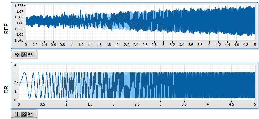
Quick background, I am in a position a signal with a ripple of mV ~ 10 with V 1.6 bias. I'm not interested in DC, only the AC signal but the NOR-9205 has only DC coupling. The application is a circuit where I expect simulations noise past the circuit must be greater than the higher noise frequencies. In the waveforms attached the background plot is the applied signal, and the top graph is the signal arising after that the signal was mostly annihilated. The two waveforms are measured with the NOR-9205.
I am aware that this measure is less than the precision of the NOR-9205, which has a maximum precision of ~ 3 mV in his +/-5V range. However, if I can't at least on the basis of shape which is good enough for me. I'm also now pretty curious that data acquisition is actually to create this
My best idea, is that it is a product of internal multiplexing of the 9205 with the DAC.
The first plot shows the waveform at 20 000 Hz, which is what I expected:
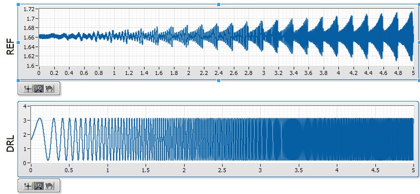
The second shows the waveform at 20 001 Hz, which seems to be modulated with a backup sawtooth:
The waveform looks as expected for 20 000, 20003, 20004, 20005, 20008, 20009, 20010 and Hz 20011. The waveform looks like modulated to 20001, 20002, 20006 and Hz 20007.
Ideally, I would like to understand this problem so that I can configure the measure in a stable way that I can count on the basic shape of the wave. Has anyone seen something similar?
-
Measurement of low-cost input analog (4-20mA) with data acquisition
Hello
I would like to have a very low cost measurement system loop which I can plug in my laptop current:
I have a load, which is connected to a circuit of air conditioning/signal booster, which output a 4-20mA. I want to measure this current loop signal.
An idea for the lowest cost system? I think that the most NOR DAQ are too expensive and too exaggerated.
I have LabVIEW.
Use of remote sensing current low-value resistance, then measure the fall of voltage through it with the help of an acquisition of data 6008/6009? They have about $150.
You will probably need to amplify current-sense with a MAX4372 or similar resistance to achieve a result that allows you to use a reasonable scale on data acquisition. I measure the current through our products in almost all of our equipment to test in this way. The size of the resistance of meaning as a result. The 6008 is accurate enough, but it is not the fastest nor well presented. But starting at $ 150, they are hard to beat.
-
2 channels of AI on a data acquisition with the range of different sensitivity
This vi is based on the 'new project' state machine on the home screen at the start of LV.
A time loop is parallel to the main loop of the state machine, shown in the picture.
It works continuously until you press the Exit button.
The problem seems to be in start this... > read >... stop start > read >... stop along the error line.
The reason for this clumsy arrangement power is measured voltages are in two lines of different sensitivity.
The shunt voltage is small and needs-. 2 to the range of V.2. The load voltage is greater and 09:50 V range is good.
In the initializing state, two separate vi 'create a channel' have been used to specify the range of voltage to the physical channel. The corresponding tasks are sent via via local variables.
DAQmx errors happen randomly, sometimes the first iteration, sometimes the 50th.
I tried to disable one or the other start > read > stop for the shunt voltage or load.
I tried replacing them with the DAQ assistant.
I tried various DAQmx vi: "wait" and "accomplishment of the tasks by resource cancel selected".
But error-50103 "specify resource is reserved" keeps popping up.
Is it possible to create two tasks on the device even when they are not used at the same time?
The only reason is to measure in two voltage ranges.
Win 7 Pro 64-bit
2014 LV database
Data acquisition equipment: USB-6210
Thank you.
This has been discussed many times. Do NOT use separate tasks. You can use different ranges for different channels with a single task. Just wire the task from one channel to another channel to create task.
You also use local variables when they are certainly not needed.
-
Real-time display at the high frequency of data acquisition with continuous recording
Hi all
I encountered a problem and you need help.
I collect tensions and corresponding currents via a card PCI-6221. While acquiriing data, I would like to see the values on a XY graph, so that I can also check current vs only voltage/current / time. In addition, data should be recorded on the acquisition.
First, I create hannels to analog input with the Virutal DAQmx channel create, then I set the sampling frequency and the mode and begin the tasks. The DAQmx.Read is placed in a while loop. Because of the high noise to signal, I want to average for example every 200 points of the current and acquired for this draw versus the average acquisition time or average voltage. The recording of the data should also appear in the while loop.
The first thing, I thought, was to run in continuous Mode data acquisition and utilization for example 10 k s/s sampling frequency. The DAQmx.Read is set to 1 D Wfm N Chan N Samp (there are 4 channels in total) and the number of samples per channel for example is 1000 to avoid the errors/subscribe for more of the buffer. Each of these packages of 1000 samples should be separatet (I use Index Array at the moment). After gaining separate waveforms out of table 1 d of waveforms, I extracted the value of Y to get items of waveform. The error that results must then be treated to get average values.
But how to get these averages without delaying my code?
My idea/concern is this: I've read 1000 samples after about 0.1 s. These then are divded into single waveforms, time information are subtracted, a sort of loop to sprawl is used (I don't know how this exactly), the data are transferred to a XY Chart and saved to a .dat file. After all that's happened (I hope I understood correctly the flow of data within a while loop), the code in the while loop again then 1000 samples read and are processed.
But if the treatment was too long the DAQmx.Read runs too late and cycle to cycle, reading buffer behind the generation of data on the card PCI-6221.
This concern is reasonable? And how can I get around this? Does anyone know a way to average and save the data?
I mean, the first thing that I would consider increasing the number of samples per channel, but this also increases the duration of the data processing.
The other question is on the calendar. If I understand correctly, the timestamp is generated once when the task starts (with the DAQmxStartTask) and the time difference betweeen the datapoints is then computed by 1 divded by the sampling frequency. However, if the treatment takes considerable time, how can I make sure, that this error does not accumulate?
I'm sorry for the long plain text!
You can find my attached example-vi(only to show roughly what I was thinking, I know there are two averaging-functions and the rate are not correctly set now).
Best wishes and thank you in advance,
MR. KSE
PS: I should add: imagine the acquisition of data running on a really old and slow PC, for example a Pentium III.
PPS: I do not know why, but I can't reach my vi...
-
Graph of the Excel data with overlay of dynamic data acquisition
Hi all
I was next to the forum of Labview for about a year, it's the same with my programming so I'm a little rusty. I don't have someone code this for me, but just a quick plan high level to point me in the right direction. I am able to work through the tutorials Excel etc.
Task 1: Basically, I have a set of data Excel (2 to 6 columns of figures, not the time) I want to read in Labview and throw in a XY graph as the base model that remains visible all the time. This data set is quite long, length vs. size (length is 100km, 1 m intervals). I essentially want a scroll X graph to display all of the data.
Task 2: Acquire a direct serial data string which will be superimposed on the graph of task 1 model. Acquired essentially data comparing data in real time to previously.
In the past, I made the simple projects with Excel data reading and also the reading of data in series. What I'm not clear on is how to create the (static) graph with Excel data model while superimposing live data as it comes. It is the basis of an annual check of the investigation process.
Advice on the process would be appreciated so I'll be working through the nuts and bolts.
Cheers for any help,
WesIf you are worried that your data sets is too large, then run a test with simulated data to see how LV takes it. You might be surprised. In all cases, you should be aware that the chart control will need to redraw it with any changes you do anyway, and as far as I know, having a large amount of data is the main thing that can make a slow chart control. If you find that you have too much data, you might need to decimate it you based on how much you zoom before putting it in the graph.
-
Several timers loop data acquisition
Hi all
I am developing a VI for FPGA Deployment. My equipment consists of a chassis/controller for cRIO-9072 with module 1-9211 thermocouple, card SD-1 module, 3-9215 HAVE modules and universal modules 2-9219. I will collect data of two thermocouples on the 9211, 14 channels on 9215 channels and 6 on 9219 modules. This system communicates to the host via ethernet.
I have prepared a vi (see attachment), which used two DMA FIFO for writing data to data acquisition at a different speed. I will be sampling the s and 9211 9219 much more slow (500ms by samples), than other channels (40 ch/kech. / s). Currently, my FPGA vi trying only to taste two different modules. When I run the present on the host vi and try to read the data, I get only extracts of the data at different intervals. If either of her would reveal latency with the connection or the host vi failed to refresh quite quickly? I am relatively new to labview, so any help is appreciated. Thank you.
Gaussy
Hi Guassy,
There are a few things that you need to change:
(1) you must separate your acquisition in the FPGA in two separate loops if they have to operate at different speeds. As it is, probably will run at the slower speed of the two parameters.
(2) you must do the same in your VI in real time, or set up the DMA readings so that they will be read at the same pace. For example, suppose that a single module acquires 1000 hz and the other at 200 hz. If you want to read 100 samples from the first module (so your reading will occur at 1000 hz / 100 samples = 10 hz), you will need to read 20 samples from the slower module, so it is synchronized with the first module.
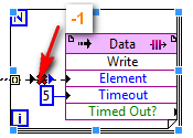
(3) your timeouts are too short on your DMA readings. Your slow acquisition is 500 us. It will take 50 ms to read 100 samples requested, but the delay is set for 10 ms, so 4 times over 5 playback will return nothing.
(4) you use graphics and no graphics. A chart will only show the current data buffer that was written for her. Refresh rate of the façade is nondeterministic, so that you can't see every update. If you use a chart, the chart will record all data written on it to the indicated depth (default is 1024 elements).
Also remember that you can have three FIFOs DMA between the host and the target FPGA, so use them wisely. It is often easier to perform your purchases on the FPGA at the same pace and send them through the DMA FIFO even in VI in real-time. If you need a few channels to connect at a lower rate, you can always throw the excess samples (there are some decimate wave screws that are perfect for this).
I hope that helps!
-
FPGA - DMA with several cMoudules
Hello!
I have a Setup with a cRIO (cRIO-9114 chassis, controller cRIO-9025) and four cModules, NI 9225, NI 9227, NI 9232 and NI 9239. The 9232 NOR has a max of 102,400 kS/s sampling rate, while the other three have 50 kech. / s.
I use DMA FIFO to transfer the data from the FPGA and there are only three DMA channels. Since the 9232 NOR has a sample rate most high, I used a DMA FIFO transfer data for this add-on. But for the rest cModules, I want to transfer data from each of them in some cases while in others, I am only interested in the data of one of them. It is advisable to transfer all of them in a FIFO DMA? Is it possible to use a FIFO DMA to transfer data for all four cModules?
Thank you!
If you transfer a lot of data for the code in real time, you must make sure, you can manage the treatment of it, which will be a lot of data to receive, process, store/transmission etc.
But in any case, it is certainly a good idea to use a DMA for data 9232. For the three other modules, if you are only interested in a number of modules whenever you read from them, then you must implement a policy for the reception of data through a second DMA channel.
A solution might be to precede the data with a unique value, also sent through secondary DMA, which defines the incoming data. For example, you can use a condensed binary byte (upconvertis to any type of data do you cross the DMA), in which the first three bits declare what modules are actively playing. So for 00000111 you read from all of the modules, with 00000101 you read modules 1 and 3. The amount of data after this condensed binary byte will depend entirely on the modules that you are reading from, clearly the maximum number allowed will be for the three modules, but in all cases, you can go out and prepare to receive the end of RealTime data properly.
It's just a suggestion. There are better options, include leaders from Pack and terminators, in which case precede you the binary byte condensed with a known value to provide guarantees that the DMA buffer is always synchronized, but these concepts are difficult to describe in a single thread post...
Maybe you are looking for
-
Why have I not apple pay add credit card option
Latest phone 6s and valid Australian credit card (ANZ). Go to the portfolio app and no option for apple pay or add credit card?
-
Error 1406 when installing Office 2010
I try to install Office Professional Plus 2010 on my cpu. I have Windows Vista Basic. I get 1406 Setup cannot write the value of key for the registry key path. I need help
-
De : Boxcard I have not been able to get rid of this spyware. I bought two programs already that were to withdraw, but they did not work. Can someone please help? -- Confused Boxcard
-
want to make action on the menu (on the program)
Hey guys what's up I am doing an action in the application menu, I did the action and took the title, but I don't know where to implement what happens if the action is triggered, I looked in the documntaions on the blackberry site and have not found
-
Update of Varchar2-PrimaryKey in master / detail
HelloI use a form master / detail with a primarykey as varchar2 in apex 4.2.When you try to update the primarykey value in the detail form, I get a ORA-01403: no data found.Is there a way to avoid this problem easily?Thanks in advance...