Draw text on the XY graph
Hello
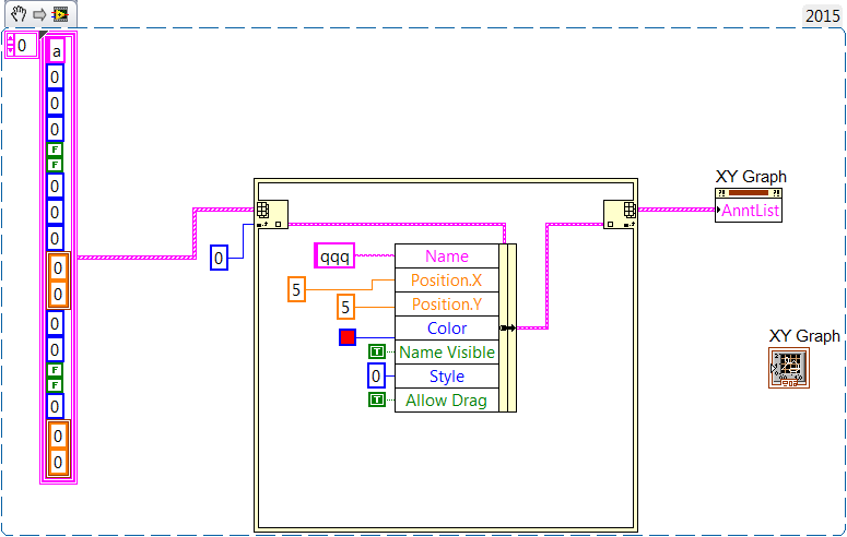
There is a technique to draw a text note on graph XY.
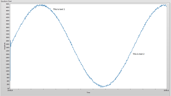
For example the text "AAAAAA" put near the upper left of the XY graph.
Thank you.
Previous version is wrong: this only works if an annotation already exists on the chart.
If no annotation it does not work.
Here is the solution for the empty graph:
Tags: NI Software
Similar Questions
-
Draw text on the graphic waveform Plot
I need to understand how to draw text on a waveform graph during execution. This could be a text box, a picture of the text, a label and an additional plot with text... etc.
Yes, I know a graph would be better than this, but need to use a graphic for my application.
The graph is updated every second, and new data are added to the history of the ranking. (Which means that the chart bigger every second) So if I draw the text above or behind the table, I'll have to update their location every second. I'll have to use card to XY Coords in an event, (mousedown or mouseup) to place the text (or image of the text) in the field where the user clicked.
Step 1 to resolve this problem is to find first class, learn how to draw or text on the plot of the graph area.
Does anyone have ideas of how this could be accomplished, or some ideas of a sneaky work around to make this work?
Example:
Unfortunately, graphics (graphic and graphic waveform XY) have support Annotation and slider, exposed programmatically through properties, but the array of waveform is not.
What you could do is to place an indicator of 2D image that corresponds to the size of the chart above. Make the value of the image that you draw be transparent and just print the text with transparent backgrounds. However, I do not know the considerations on the performance of it - many times user interface elements, overlap (portions of even transparent) can cause problems of performance due to forcing redesigns... then again maybe a graph is always be redrawn in any case.
-
resize the text of the xy graph axis
Hello, I have a question about XY charts:
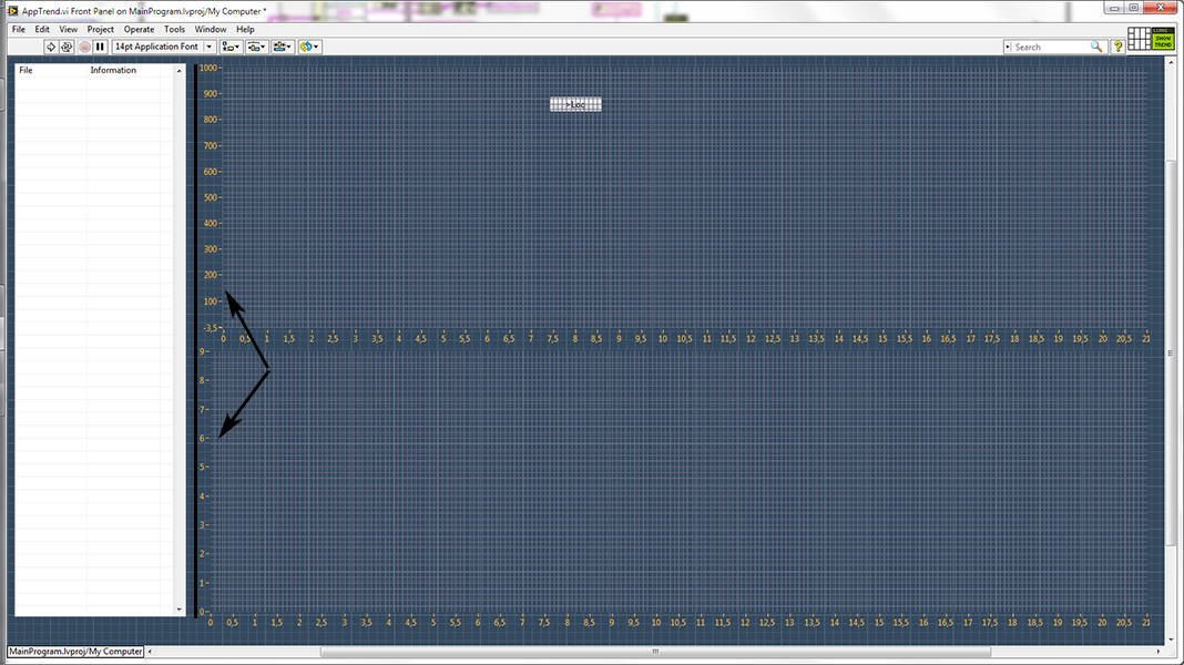
I want to have both XY-graphs with identical sizes aligned perfectly to have a nice comparison of the separate sets of data without their trace on the same graph. However, I can't find out how to set the width of the text y axis. Because now when the width of the texts are not the same, even if the whole graph has the same region and departure (continuous line on my pcture), areas of land are a little off (indicated by arrows)
Peux I put somehow the width of these texts, as well as areas of land worth? Right now I use 'Position' and 'Size of the area of the land' properties of charts XY to make them also of size.
Thank you
Your VI has not all data stored in it as a default.
When I used the %10.0f on your VI and set the scales, the results were better than nothing, but not perfect.
I don't know if this method would work perfectly. With a font that is not fixed width, the actual width of the text could very slightly. The width of the different numbers could be different, and the width of a space character to fill the text when there are fewer numbers can be different.
-
Draw text within the rectangle in OpenGL
I want to draw text in a rectangle and I also need to make sure that the text does not go beyond the limit. Can someone give me some idea/advice for this problem in OpenGL?
Yes on the link below.
https://github.com/BlackBerry/NDK-samples/tree/next/HelloWorldDisplay
-
How to draw text bordered on Bitmap usgin class Graphics?
Hi guys.
I'm drawing text on a line graph.
The text color is black. Border is white (edge of letters).
How to draw like this?
Thanks in advance.
If you are interested in a vaguely similar effect, but without all the subtle shadows, I have a suggestion. Draw the white text, several times, gap between the nominal position of a pixel or two in different directions and then draw the text in black at the nominal position. The idea is that white copies create an enlargement of each letter which becomes an overview when you draw the black letter on it. You may need to do this a letter at a time, allowing more space between the letters, rather than draw the entire chain at the same time.
-
Hi all
I'm having a problem with BitmapField.
I'm tring to draw text on the scope of the Bitmap.
The purpose of this is that if the field has the focus, change image and attract white text and vice versa.
But it seems that the text drawing image behind.
Please help me on this.
Thank you
DK.
Here is the code:
        ttsField = new BitmapField(tab_off, BitmapField.FOCUSABLE|BitmapField.FIELD_RIGHT|
                BitmapField.FIELD_VCENTER)

        {
            protected void layout(int maxWidth, int maxHeight)
            {
                    super.layout(tab_on.getWidth()+2, tab_on.getHeight());
                    setExtent(tab_on.getWidth()+2, tab_on.getHeight());
            }
            public void onFocus(int direction){
                //invalidate();
                setBitmap(tab_on);
                    hasFocus = true;
                    //super.onFocus(direction);
            }
            public void onUnfocus(){
                    hasFocus = false;
                    //invalidate();
                    super.onUnfocus();
                    setBitmap(tab_off);

            }
        protected void paint(Graphics g)
        {
            if (g.getBackgroundColor() != 3098850)
            {
                g.setBackgroundColor(0xfafafa);
                        g.clear();
            }
            super.paint(g);
        }
        protected void drawFocus(Graphics g, boolean on)
        {
//          if (hasFocus)
                g.setColor(0xffffff);

                g.setFont(Utils.BBMillBankTall(12, Font.BOLD));
                g.drawText("Text to Speech", 0, 0);
                super.paint(g);
            }

        };
You have your sequence of events backwards.
Call the super.paint (first), then the text above the image bitmap drawText().
-
draw lines on the graph of the intensity
I want to draw lines on the graph of the intensity.
I am already looking for some questions before.
I know there is a vi could draw line on the graph of the intensity by dragging the mouse.
But I need more precisely what set the length and the angle between the horzontal line.
The setting is very ideal for me. But I don't know how to use it in the intensity chart.
Is there anyone can help or give some advice?
Your example is not so great because it uses 100% of CPU on a kernel at any time, do nothing.
Here's a quick rewrite of my old example here. He draws an angle with the specified length and angle to where you click on the chart. This should help you get started. Modify if needed. (Also remember that trigonometry is much easier when using complex numbers
 )
) -
How to type vertical text from the bottom up with the right orientation for a graph?
How to type vertical text from the bottom up with the right orientation for a graph?
Hello! Below, I'll demonstrate how to have vertical text in two different ways.
Example 1:
1. below, I have a graph and want to label the vertical axis.

Select the text tool, and then the Vertical text tool.

2 with the vertical Type tool, I tap on my vertical label.

3 with the move tool, then I can orient the text in a position desired, as shown in the examples below.


If this isn't the desired orientation of the vertical type you would like. I have the example 2 below.
Example 2:
1. After typing my text vertically with the Vertical Type tool (in example 1), I want to move to a horizontal position. I can go up to the options panel and select the icon "show/hide text orientation", surrounded by below. It will pass the text back and forth between vertical and horizontal.


2 after the passage of the text to be horizontal, I want to change the orientation of the text, so it is aligned with my vertical axis. Go in Edit > transform > Rotate as shown below.

3 you want to can Rotate the text as indicated below.


4 text is not in the right position we want, so we have to move the text, as illustrated below. Press enter/return to perform the complete transformation.

5. the text is shown below.

Other links:
Please post back with any questions,
Janelle
-
AppleScript to save the text from the view of results
Hello, I am working with applescript that takes the results in the window at the bottom of the editor, like this

Now I try to write it in the text editor as a text but Applescript say that he can not with "can't turn"class IFAP in the text.

and if I try to save the results as a list, applescript supports error 10000 (textEdit has encountered an error: failure AppleEvent written in popup)

It's that everybody knew how can I solve this problem?
Here is the text of the script, but it won't work on your mac because it uses application to imagine Photo.
thisFile to Choose file with guest "choose an image file:
say application "Imagine the Photo.
the value thisImporter for import graphics thisFile
if the component error of thisImporter is not equal to 0 then
thisImporter close
display the dialog box "Not an image file that quicktime recognizes."
return
end if
the value {x, y, xDim, yDim} to the limits natural of thisImporter
define thisDocument to make new document window properties {size: {xDim, yDim}}
the value the destination of thisImporter to thisDocument drawing
thisImporter trace
thisImporter close
-The section which follows should be replaced according to the pixel value class
the value pixelValueRect to {x, y, xDim, yDim}
the value pixelValues1 to get the pixel values of thisDocument with properties {class of pixel values:pixel in the rectangle, rectangle boundaries: pixelValueRect}
thisDocument close
-class (pixel points) as a list
-' class pCol' as a list - цвета координаты разнесены по классам с именами, приводим к списку и
end say
say application "TextEdit".
activate
make a new document
the value text of document 1 to pixelValues1 as list
-the text of the document 1 pixelValues1 as a value list
-Save the document 1 in ' / Users/IMac/Desktop/LastUpdate.txt '.
end say
pixelValues1
-
Multiple and different axis-related channels are on the same graph
Hello
I searched the forums and google trying to find out how to trace my 48 channels in a single chart and according to the plots of units he value axis 1 of 4.
I have 48 channels all of them share the same time base axis.
48 channels are mixed of flow, pressure, Temp and other bag. The units are located in the 'Units' property to the string.
I would have 4 axis to account for my 4 units and hold all 48 channels to draw on the same graph, aloted to the axis of sorts.
Thank you I have maybe for what is right, as it is a small segment of my script script. Help, advice or information would be greatly appreciated. I am struggling to find documentation to know where to start with this.
Best wishes
KR
Hi KR,.
After talking to my colleagues, I think that you can now have a solution to this, but for the benefit of third parties, the solution is to use "Related curve" scaling in the axis system display 2D of the pane window VIEW. To have this feature enabled you must be using n or n axes systems.
More information can be found here: http://zone.ni.com/reference/en-XX/help/370858M-01/dlgview/dlgview/view_scaling_manual_dialog/
-
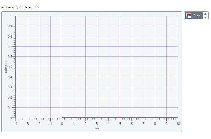
How to draw 2 tables on a graph?
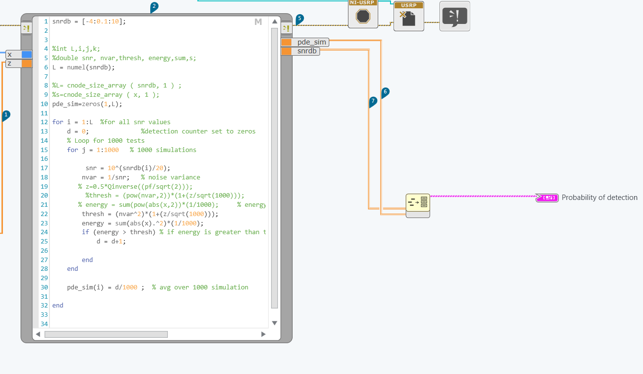
In fact, I'm trying to draw 2 tables the mathscript node .one depends on the other. I did a cluster for the 2 bays and led to plot in the chart, but the chart doesn't really show the exact values.
I want to draw pde_sim which depends on the snrdb.
the figure resulted that I get is:
Is something wrong with my code?
See duplicate:
-
Update the text of the label on a XControl via a property
Hi all
I write various programs to help with the debugging of embedded systems. I often need to convert a value to byte into pieces and then show which of these bits are true/false. This is easily done by using the convert-bool-Bay VI. However, I would like to create a control that will allow me to display a name for each field of bits - a bit like the way records are described in the data sheets. The control must be a bunch of buttons, and then I can show the bits are true/false, and use the label of the button to hold the name of bit field.
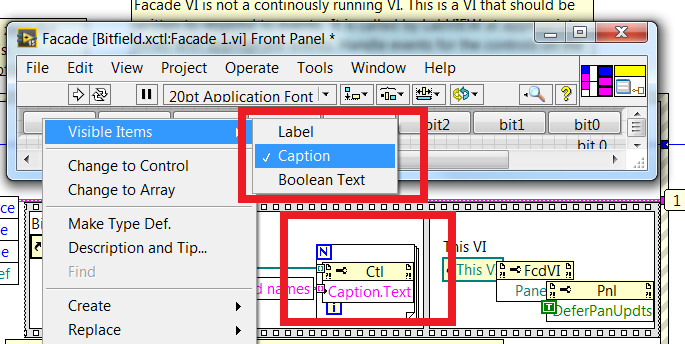
I went from one way to the creation of this feature in an XControl as this seemed the best. My group of updates to Boolean values correctly according to the value of byte brought into control. However, I use a property to set the Boolean control label text (names of bit fields). My debugging shows that the text is assigned to the label of the control, but the control panel never changes. I tried synchronous updates, and by forcing a new drawing of the Panel using DeferPanelUpdates does not.
I would be grateful for any help on this - VI and XControl demonstrating the issue is attached.
Thank you
Ray
Probably, because you try to change the text of the label. Try to change the text of the legend...
For each boolean, choose "visible elements of legends '...
-
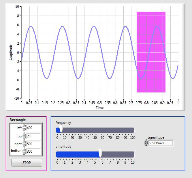
Hi, I want to programmatically draw a rectangle on a chart XY (XY Graph.vi Build). I know where the 4 points are on the coordinate chart but I can't yet draw using the block Rectangle to draw. Could you please help me how can I draw a rectangle in a graph. I am attaching the photo to this message
Hi guys,.
I thought it was interesting questions - and, although I had not tried anything quite like this before, I thought I would give it a whirl. smercurio_fcsuggestion was excellent - I find the code referenced in LV example finder, in the fundermentals > graphics & graphics > plot pictures folder.
Attached are 2 pieces of code.
DrawRectangle on Graph.vi allows users to define the rectangle by cluster of façade.
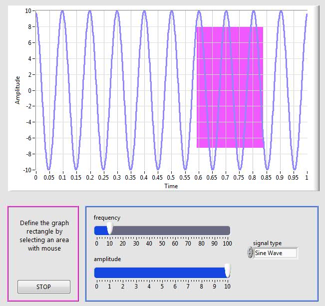
DrawRectangle on graphic .vi (events) allows the user to define the rectangle by clicking and dragging on the chart. Please note that the code requires that you start from the upper left corner of the rectangle, and drag to the lower right. But isn't that a creative logic would not solve - if you wanted a bit more flexible code.
You should also know that I have not spent a lot of time on the code, so it is not perfectly architected. But we need to think!
Best wishes
-
several land 3D on the same graph
Hello
I use the 3D library CW graphics.
I would to draw 3D curves on the same graph: is it possible?
To draw my curves, I use: CW3DGraphLib__DCWGraph3DPlot3DMesh (graphHandle, NULL, xVt2, yVt2, zVt2, CA_DEFAULT_VAL)
Thank you...
Adeline
OK, it's great that I found that it did not work!
I had to add in some places:
CW3DGraphLib_CWPlots3DItem (plotsHandle, NULL, CA_VariantShort (1), & plotHandle);
CW3DGraphLib_CWPlot3DSetMultiPlot (plotHandle, NULL, VTRUE);
CW3DGraphLib_CWPlots3DItem (plotsHandle, NULL, CA_VariantShort (2), & plotHandle);
CW3DGraphLib_CWPlot3DSetMultiPlot (plotHandle, NULL, VFALSE);Ciao ciao
Adeline
-
Multiple channel for the XY graph
Im trying to draw a table 1 d in the y-axis and sometimes in the X axis. When I probe values since the wire connecting the XY graph, I see the values also perfect that I need them. But I do not see the values on the graph.
Able to do the same thing with a waveform graph, but a chart XY im gives me a few more flexibility and benefits...
Thank you
Gokul Krishna S
Hi Eureka,
There's a Subvi, that you do not attach with this VI, and I can't run it.
Part of your problem is that your x axis has a single value rather than an array of values. If you right-click on your chart and select Properties, then go to the locations tab, you can change views of marker. If you do something larger than a single pixel, you should be able to see it on the screen.
Please also take a look at This example of community to the XY graphs.
Thank you
Lisa


Maybe you are looking for
-
Firefox has completely disappeared from my Apple PC - cant find anywhere - whats happened?
I have a laptop Mac OS x 10.6.8 running version. Firefox has been installed more than two years ago and has been used exclusively for Internet access, browsing through Telstra wireless cable. Yesterday, I noticed that he had moved his position on the
-
I had a linear new extreme connection (connected to the wireless model Cat5) related to the old extreme then Express (newish). I would have put in place using airport Utility (for example) 4 years ago and has worked well. I changed my wireless modem
-
Qosmio F10 - cannot install drivers for some hardware components
Hello I decided to reinstall Windows XP SP2 again, given that the laptop was full with a lot of garbage and slow work. I've done it before, and it has always worked very well, but this time it does not recognize my sound card, network card, graphics
-
Why did I receive a call from someone who claims it was techfly... and they called registered users of windows on malware?
-
Impossible to rename folders: restores the original name
Original title: file rename rename my computer won't let me not rename folders. Can I rename the files, but not files. I click with the right button on the folder, click on "Rename", enter a new name, press the "enter" button, but nothing happens. Th