Exchange of parameters between MCI and IP IVR
Hello
How can I get or post parameters between MCI and IP IVR. These parameters can be used for advanced control of calls, but at the moment I don't have not managed to make these components between them 'talk' with variables.
Thank you.
Hello
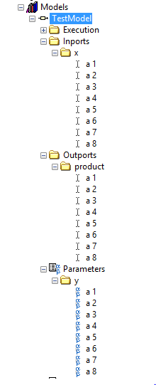
You can use for this purpouse the 'Business Get call Info' (data of the IDC to the IP IVR) and 'Business Set call-Info' nodes (IP IVR to CIM data) to SIR script Editor.
Select from one of the nodes properties and on the 'Général' tab you can get/set the values of the MCI devices Variables (click on the 'Add' button and in the new window you can access these variables in the "Name" drop-down list).
You can change the "expanded call Variables" in these nodes in the tab ' Variables to call expanded.
Hope this helps,
Juan Luis
Tags: Cisco Support
Similar Questions
-
Time between MCI and Test secure Channel
Hello
When I was hired in my company in February, I had the 5.0 VMWare CIM class. I just move to the study to take my VCP 5, but some of my colleagues said that they were informed by the instructors theres a delay of 3 to 6 months after the ICM to take the VCP in otherwise you can return to the ICM. Anyone know if this is true or not?
Thank you
Shaun
Log your profile here:
https://myLearn.VMware.com/MgrReg/login.cfm?UI=www_cert
Once connect you click on "myTranscript" on the right side and then you should see that CIM listed under 'courses '.
see you soon
GAV
-
Connect the large number of parameters and variables between Verstand and model of Labview
We have an installer of dyno with a chassis PXI-E running Veristand 2014 and 2014, inertia. In order to strengthen the capabilities and timing of the Veristand, I would use models of Labview to perform tasks is not possible by Veristand and inertia. An example of this is to determine the maximum amount of a large number of thermocouples. VeriStand has a comparison function, but it compares two values at once. This makes long and rigid emissions. LabVIEW, on the other hand, has a function which words one to get the maximum items in a table in one step. I need to use Labview to 'send' the thermocouples of 50 or more to the Labview model. In addition to the variables that must be communicated between Veristand and Labview, I also need to present Labview with the threshold and setting parameters. Forums and user manuaIs understand that you must use the connector pane in Labview Veristand System Explorer mapping to expose the inports and isolated villages. The problem is that the part of Labview connector is limited to 27 I/O. How to overcome this limitation?
BTW. I'm relatively new to Labview and Versitand.
Thank you.
Richard
You can work around this limitation by putting your orders and clusters indicators. Then set the cluster to be required or recommended to indicate whether contained controls are entered or parameters, just normal.
-
Exchange of data between the internal and external labview code
Sorry for a simple question.
I have a TestStand sequence that uses units/tests written in LabVIEW. The sequence is extermnally began with a stand alone LabVIEW program. I need to establish simple exchanges of information between units of the sequence LabVIEW and LabVIEW external code.
Information are simple strings will eventually be sent in both directions.
Please advice what commumnication path needs to be implemented.
Unfortunately, arttempts to search OR site Internet (or Internet) result in a large number of irrelevant information. Probably, I can't shape appropriate keywords. There is therefore a need for your help.
Thank you
_Y_ wrote:
[...] It takes by presenting some initial information (e.g. username) in the sequence [...]Use a Message from the user interface of query for the data (data available in the user interface, executing sequence requires it).
_Y_ wrote:
[...] and view the status of intermediate/final level in the user interface.Use a Message from the user interface to transmit these data to the display (data available in the execution of sequences, Which requires it)
Norbert
EDIT: Btw, you should use TestStand user to nicks track management. This gives you more options and security than some custom stuff implemented in the user interface.
-
Repeated loss of connection between Outlook and Exchange server
Hello
I am running Windows 7 beta ultimate evaluation copy Build 7100.
On that, I installed Office 2007, part of which is Outlook (12.0.6514.5000) SP2 MSO (12.0.64251000).
I do the usual Windows updates and recently, I noticed that my Outlook has been updated as when I turn it off, I have a new Outlook "grey" with a red 'x' icon in this document, which disappears when the software is finally off.
The problem is that now Outlook repeatedly loses the connection with the Exchange Server in my (work) and I have to close Outlook in order to reconnect and reactivate.
It only happens when I'm at home - not at work (where I am actually on the internal network).
It's very frustrating.
Can you please help?
Check with this community: http://www.microsoft.com/office/community/en-us/flyoutoverview.mspx
-
How to exchange values between ASP and Flash?
Hello, I want to swap values between ASP and Flash. I don't want to send it in the form of a querstring as:
myswf.swf? var1 = value.
I don't want my user to see or change this value.
Thank you
Use the urlloader class.
-
Display satellite C50-A546 cards how to switch between NVIDIA and INTEL?
Hello
How can I switch between NVIDIA and INTEL graphics cards?
PS
I have already installed all the drivers, but I can see that INTEL the card used chart!* OS: Windows 8.1 x 64
* NVIDIA driver: 340, 52-portable
* DirectX: 11Hello
The Intel graphics chip, which is part of the central unit should be used for low performance applications, because it allows you to save energy and reduce the internal temperature.
For best performance while game, it s advisable to use the external GPU (nVidia or AMD)
This setting can be changed in the nVidia control panel sHere, you should choose manage them 3D settings (can be found on the left in the nVidia control panel)
Now in the main window, you will find two global settings and program parameters tabs
In the program settings tab, select the (game) program that needs to use the nVIdia GPUIf it is not listed, click the Add button
Then choose the graphic processor preferred for this program (generally must be nVidia processor high performance)Last but no less, in this program-specific settings, you can assign additional features to improve performance.
-
Browse catalyst prepared - export between inside and outside as in the catalyst?
Hello world
Dear people of Sony, is possible to add a feature to export / trasncoding files between In and Out marks only as in catalyst go? Was surprised not to find, very handy when there is a large file that has two or more WB settings required, to export part of the file with the parameters a, marking the section with inside and outside and then adjusting those yet to export the or other parts of the shooting with an another WB settings?
I know there is a feature to copy sections of the files ' between inside and outside "only but it would have been more convenient to have it as in catalyst browse my humble OPINION."
Or is there a simpler workflow that I'm missing out on?
See you soon
Max
P.S. Thanks to solve the strange Maj WB problem that I reported earlier, Travis and team, I have since reinstalled catalyst prepare 2015 and in awe of the capabilities of the software. Great job.
Hi maximdryginsony:
Thanks for the question.
I think the function of catalyst to prepare that can solve your problem is a subset of creation. What you can do is put an In/Out point with a WB setting, and then click Log. Create a subclip (see screenshot). This will create a subelement with the color settings.
-Travis
-
Switching between microphone and line-in in the Realltek Sound Manager
Ok.
Now I know where the Realtek Sound Manager, and I can control the parameters of the microphone and speakers.
But how can I switch between microphone and line-in?
At the moment I don't see a line of component option snap at all. Is it because it's a kind of auto detect and the opportunity every time I connect something?
Everyone knows this, or has some experience in this regard?
Cordially in advance
FransSorry but I don't understand what exactly you want.
You have built in mic or you can use the external microphone connected to the mic-in port.
When the external microphone is connected a resident will be disabled.The question is: what do you want exactly and for what purposes? Please explain what is the reason for this switching between mic and line-in port?
-
Problem with the published parameters between the movement of FCPX
Hello
I have a little problem with the settings published between the movement at FCPX.
For some reason, the published parameters have different values within FCPX in movement.
For example, in motion, a parameter is - 187.04 and in FCPX is-0,19. What are the parameters of position for CSOS.
If I try to change this setting in FCPX, the application crashes after 10 seconds or less.
No idea what is causing the problem? I re-edited the effect several times, same result. The software that I use is FCPX 10.2.2 and 10.2 of the Motion.
MOTION

FINAL CUT X

Thank you.
The values that you have published on the move have been compared to this project that you created. The values shown in FCPX are "consistent" with any project that you create. Often, you will see the center screen is 0.5, 0.5. Left and below are 0, right and up are 1.0. Or you could see Center of 0.0 and a range between - 0.5 and 0.5. Sometimes, you will see the numbers on the scale of some sort of percentage (vertical values will be 0-100 [%] and the horizontal will be based on the aspect of the project, for example, horizontal will be between 0 and 177.7778 for a project of 1920 x 1080, etc..) It will depend on the type of object and the parameters associated with what you posted.
If you want to "correct" values in FCPX, you will probably need to rig settings, otherwise, just live with it.
For what is * why * your model crashes FCPX, that will be another reason and not the difference in the numbers. So, can we get more information on the model?
To use specific fonts?
You publish alterations settings?
Anything out of the ordinary?
-
Localhost UDP connection between FCR and Matlab
Hi all
I have a question about the connection between Matlab and FCR UDP. My idea is to Exchange data between Matlab and Labview on the same computer.
So I found the 'UDP Simple' of the FCR 2.0 sample project where periodically a datasample is generated randomly and sent to the remoteport 61557 local host. In the project a 'fractional number of string for transmission' is used for the transmission of data. The receiver of the sample project reads from the same port to receive the datasample.
Now, I'm interested to read this simple stream from Matlab (just at first), however, it does not work and I'm not sure why. What I do in Matlab is the following (code Matlab)
delete variables;
u = udp ('127.0.0.1', 61557); % Of installation UDP Object
fopen (u); open reading port %
A = fread (u, 1); % read an element
fclose (u);With this code, however, I get a timeout by saying: "' WARNING: unsuccessful reading: the amount of data specified has not been returned within the time limit." "
I'm not sure why this happens, maybe you could help me out here? I guess that the formet serving to VCF is not the same as in Matlab? Maybe the Terminators are not the same?
See you soon,.
Steve0
Hey
So, regarding the problem actually, I found the solution today. It was not the firewall, but a simple configuration in Matlab seting the UDP port. So the side of Matlab, to change the definition of udp object according to
u = udp ('127.0.0.1', 'Thelocalport', 61557);
If you have
u = udp ('127.0.0.1', 'Thelocalport', 61557);
fopen (u);A = fread (u)
fclose (u);
Delete (u);Who does the trick and you can read from the port. Then of course you say Matlab that you read from the "LocalPort" x, which I wasn't aware of.
On the transmitter side, you simply:
u = udp ('127.0.0.1', 61557);
fopen (u);
fwrite (u, '1');
fclose (u);
Delete (u);Here, you set just the port of transmiting.
About the format of the data: I used the simple UDP protocol streaming Comms project where a random number is generated as a double, transformed into a string (ASCII values) and transmitted. At the level of the receiver, you get as much the UDP packet with the ASCII values that you must turn if you want to find the number.
I hope this helps anyone having the same problem.
See you soon
-
How to make the exchange of data between 2 whole loop real-time
Hello
I have 2 while loop
the 1st loop includes data acquisition program
the 2nd loop includes control program
--------------------------------------------------------------------------------------------------------------
My question is how do the exchange of data between 2 whole loop real-time--------------------------------------------------------------------------------------------------------------
I tried with the variable and direct wiring between the 2 local while loop
It does not work (there is a delay)
-
VISA writing differs between TS and LV Run - Time Engine development agencies
Hi all
I made a request on LabVIEW to test the BERs (Bit error rate), and I used the Write VISA between two COM ports to Exchange data.
Everything works great using just of LabVIEW.
Later, I used TestStand to call my application (VI). Adapters of LabVIEW TestStand have been set by default on the development system , and everything works OK!
Finally, I had to disable the development system and to define the types of adapters LabVIEW of TestStand for LabVIEW Run-Time Engine and I noticed that the speed of the exchange of data between two COM ports significantly decreased.
The only difference was the speed... because all data (changed slowly in this case) happened correctly on the other COM port too.
The symptom was the same that decrease baud rate... but baud rate and all other configurations remained the same. The only difference was the change between the development system for the runtime to notice this reduced speed between the data exchanged using VISA Write.
All the solutions for this?
Thanks in advance
João
Hi all!
I'm sorry, I forgot to reply to this thread...
Solution was change the way VISA WRITE of "asynchronous" to "synchronous" to book a thread just to WRITE visa.
The problem here was something like this (?): TestStand used all available threads and when we wanted to WRITE of VISA, the thread has been busy and VISA would wait until the wire emerges. After changing to syncrhonous, there was a thread dedicated to this process (?).
Now, everything works the same using LabVIEW Run-Time Engine or system deployment.
Thanks for the help Chris and Norbert :-)
João
-
Delay between angle and entered analog on a 6221
Hello
my test setup consists of a (8184 current run LabVIEW RT) embedded PXI controller which uses a PXI-6221 of data acquisition. One of the outputs analog of the 6221 creates a demand for speed that is sent to a servo controller. the servo drives then the test configuration. Between the servo and the remaining test configuration, a quadrature encoder is located. Both the 6221 meters are used to measure the position of the servo (using the trains of pulses A and B) as well as the speed of the servo (frequency of A pulse train). In addition to these counter inputs, some analog inputs of the 6221 serve as well to recored the configuration of test signals.
In this configuration, one of the analog signal has a frequency of n periods per revolution of servo (determined by the mechanical design of the test facility). But when I leave the servo turn to for example 100 rpm, then decelerate from status quo with a constant deceleration and then draw the analog signal against the measured angle, I see clearly that as long as the speed is telling, I n periods per turn (or a passage from my analog AC to zero each 1/2n towers); However, as soon as the slowdown begins, the plot gets stretched along the axis of the angle (so the plot tells me there are less than n analog periods per turn, which is impossible because it would require the mechanical destruction of the facility).
However, I can calculate a position based on speed information signal, as I got to the second counter (by integration of the speed). When I do this for the above velocity profile and draw the analog signal against the calculated angle, I see exactly n times / revolution, no matter how fast the installation program is rotating (just the expected behavior).So, apparently, the speed measured is "in phase" with analog signals, while the measured angle has a "phase error. Draw the angles measured and calculated against the time tells me the same thing: the measured angle is always late (compared to the calculated angle). The period is not constant throughout the measurement; I've seen values between 30 and 170 ms within a single record. Due to this change of variable, inserting a delay for all channels, but the angle is not a great idea.
Unfortunately, calculation of the position of the speed signal is no option for me, because the direction of rotation is changed during measurement; because speed information I have based simply on a frequency of pulse train, it contains no information management, therefore a calculated position would be unaware of the changes of direction.
Does anyone have an idea whence thios delay and what I can do to fix this problem?
Try a position different methods of decoding or exchanging the meter channels has not made a difference.Thank you!
Hey Kevin,
attached you will find the last block diagram (no new translation this time, since no changes have been made that require a), which includes your last suggestions (explicitly start the task of AI, remove the excess constraints) with a flat sequence structure that applies all the preparations of task to finish before the start of the first task (I know I could have achieved the same effect of intelligent routing of the signal error, but I think the code is) better readable this way).
Without OPI, LabVIEW tends to start to have, ao and tasks of the angle of the very different moments, which (for some reason that I don't understand - we have a sample clock based calendar here, and the sample clock is run, well after the three mentioned tasks...) tends to cause delays in the order of several 10-100 ms between tasks. With the structure, this problem is eliminated.
The Sub - VI just above DAQmx writing contains the "conduct" code that I used in the last screen shot to "serialize" the requested speeds - in this way, the table that contains the requirements of speed does not need to be rebuilt.
The code that creates a weather channel frequency implicitly timed measure left the VI shown here in a second VI that is running on the host computer, because everything that involves a calculation and does not require any intzeraction with the DAQ hardware is better placed there (the 850 MHz on the PXI controller celeton is slower than 2 definitiely something host GHz Dual-Core system).
The behavior you mentioned for the task "not started" HERE is what wrote using LabVIEW. I thought the block of relaxation that I had at the beginning would treat the start of the task - at least, the code like this figure repeatedly in the examples that come with LabVIEW.
I don't really understand what has caused the problems I've had - it seems that it was the combination of the measure quickly loop iteration with the start of task based on trigger HERE, but I do not understand what are the mechanisms in the background caused the problem (too forced loop was not the cause; the same block diagram works well with an additional loop timer).
If the solution was composed of the following steps:
-remove the old code calculating speed, replace it with a better code out of the main loop. This allows to
-reduce considerably the frequency of the main loop.
-Pull the DAQmx writing out of the loop, and
s ' ensure that all tasks are started explicitly just before the main loop starts to run.
-Possibly remove excess constraints of the main loop.
-
MWI delayed power on and off between 5 and 40 minutes
Unity 4.0.2 unified exchange 2000 tsp 7.02 call Manager 3.3 single does site no cluster
Hi, I have incorporated the above but got 1 problem of stuborn. the mwi on and off voltage indication are delayed by between 5 and 40 minutes, this problem is related to all users. the problem is internal and external calls. I had this problem of troubleshooting for several days. tests indicate that the message does not appear in the unityMTA but takes about 1 minute to appear in the outlook-box users, when I do a refresh on the light lamps work properly. There is no error on the area of the unit or the gc/dc boxes or e2k clients, but several positions designed, it may be DNS. I tried to add files hosts with no joy. basically is there any way that I can retry the record to know what is happening, or is it possible to force a lamp after so many seconds as a work-around. Thank you. Jim.
I wonder if the Exchange is slow to tell us...
In the directory \CommServer\TechTools there is a tool called MBXSuite.exe. Once you open MBXSuite.exe select the mailbox you want to monitor. Choose the account that runs the AvMsgStoreMonitorSvr as for RunAs. Click Notifications, and then click mailbox to logon.
Once it's done leave a new message to the Subscriber. How long does it take to see you
Notification received
TABLE_ROW_MODIFIED
?
Thank you
Keith


Maybe you are looking for
-
I've removed a non-standard bookmark, I can get it back?
I deleted a bookmark by accident. It is not 'most visited' or 'most' anything. Is it possible to restore it?
-
The message "Generic Host Processor for Win32 Services has encountered a problem and needs to close" whenever any program searches for files or folders, including the control panel. This happened after the latest windows updates.
-
I can't remove cyber security on my computer. Could someone help
I get Cyber Security tell me that my computer is at risk, to eliminate the risk, I have to buy software. I don't want that, but I can't remove it from my tray Panel or control systems. It does not allow me until I have buy there product. When I'm onl
-
How to reinstall Windows Media Codec package
How can I reinstallwindows media codec package I did a really stupid thing and I uninstalled the codec for windows media player package. now, my computer is all messed up how can I recover