exit node digital fpga Boolean realtime control
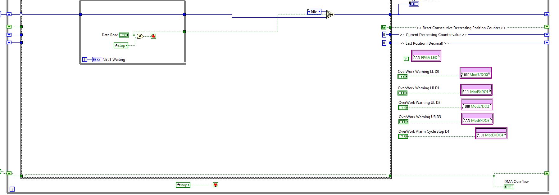
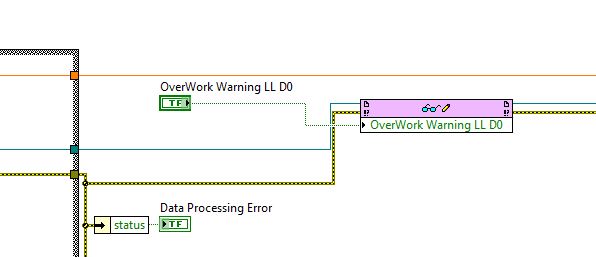
I have a system where I want to enable / disable a digital output running on FPGA.
Once I set the Boolean value on my side in real time (which turns out FPGA), I see the output turns on the CRIO, but it flickers on and OFF (do not lock?). I just want the FPGA to stay as long as the output is enabled, on the coast in real time. I can't change the mechanical action of the switch because of limitations on FPGA / RT according to labview (I get an error on compilation)
Any suggestions on how to fix this?
tman2013 wrote:
What I am doing wrong?
You reset the FPGA inside of the loop, in "Open FPGA Part.vi. You must open the FPGA reference once, outside the loop, instead of open it several times. Whenever you reset the FPGA VI, exits back to the default values.
Tags: NI Software
Similar Questions
-
How to dynamically add any control (digital button, boolean) to control the line and selected column
Hello
How to add a control (digital button, boolean) dynamically in control instead of lines and columns selected. Please suggest the idea or no matter what example code you have please share with me...
Thank you
Vieu
Essentially, that's what you're looking for:
Please note that you have to account border sizes and the label of the control so that the code does not work right out of the box. You should also check for the height and width of column and if the position is valid at all before moving around the control.
Norbert
-
In the target FPGA read/write control function?
Hi people,
I learn a lot from the sample project FPGA, including how you can easily retrieve and set controls and indicators in an FPGA using the read/write control function running in an RT target.
However, I can't find a way to do something similar in a FPGA target. I've been down this road before - that is, trying to move the data in/out a looping VI FPGA (void) to a (parent) FPGA VI - where my memory points to reach what I needed use.
So I was happy to see the palette FPGA enabled me to drop the control functions to read/write on a FPGA vi target. But alas there where tons of errors (not compatible son for target, etc.) and I guess now it's not possible.
So, just to be sure, I'm not missing something, is there something like control functions to read/write to use in an FPGA for read/write in an another FPGA (looped)?
In addition, why would I be able to read/write on a FPGA vi control functions if they are not supported? (Sorry for the n00b question)
Thank you
Steve
maherhome wrote:
You're right that I don't have this knot in my palette. However, I also do not seem to have a Refnum Occurrence in the palette is in the FPGA (see below), but I need to synchronize several loops of FPGA and added research using the textfield in the VI editor (and if compiles and runs). So 6 months to Labview and I'm fuzzy on how the palette is restricted
I don't know what you're trying to prove here. There is no control of refnum in search in your image. Occurrences are available in FPGA, and for control of refnum for one you just right click on a function of the instance and create a control. If you can create a valid thread of a certain type of data, then you can create a control or the indicator for it, regardless of the question to know if this type of control or indicator appears in the palettes. However, the functions that you can use in the block diagram are limited by what is available in the palettes.
maherhome wrote:
Regarding orders read/write for the FPGA/lights, I'm surprised that the infrastructure developed to allow read/write between RT and FPGA has not mobilized to allow read/write between FPGA and FPGA. The elements of memory function, but they are less convenient.
You may have noticed that you cannot compile the individual parts of an FPGA VI and combine them later; This is because when you compile an FPGA VI, all its subVIs are essentially merged to create a single block diagram (with additional logic if one not reentrant Subvi is used in multiple locations, this is why it is not recommended on FPGA). The subVIs no longer exist in the FPGA compiled; reading and writing a control on them would make no sense. If you want similar behavior, use global variables - but understand that global variables store values in FPGA logic resources. Using the elements of memory (or FIFO, which can also store in memory) leaves more fabric available FPGA logic by storing data in resources specially designed for this purpose.
-
Front panel FPGA Boolean mechanical action is important to control the actions of a host RT?
When a host RT controls an FPGA VI shipped through Boolean values on the face before of the FPGA VI, no matter what setting the mechanical action is used by the Boolean front panels? For example, they all just act as "Switch When you press on" or the law "lock when you press on" as one-shots?
Okay, it looks like I have a little bit of clarification to make.
First of all, the patterns of waveform above are correct. As soon as the handshaking signal Host_Write if high, the data is written to the next clock cycle. At this point, "Lock" options are equivalent to eachother, and all the options of 'Switch' are equivalent to the eachother. Each takes 150ns to receive the signal of Host_Write.
The only thing in my post above that is misleading is when I said that transitions occur at the same time. This is not true, as the writing must be serialy, 150ns apart.
In case anyone is interested, I enclose the test and the test bench project. On your host machine, simply generate the files for the simulation construction-spec, then replace the tb_NiFPGASimulationModel.vhd generated by the one I've attached (this is the test bench). This should be at "C:\NIFPGA\simulation\FPGA_Boolean_Mechanical_Action\FPGA_Target\MechanicalActionTest\user". Given that forums don't add .vhd files, please rename the .txt in .vhd.
-
FPGA controls and indicators appearing is not in the node IO FPGA.
I don't know there is something simple, that I do not. I use the pure mode of FPGA on my sbRIO. I have several controls and indicators that I added to the FPGA code since the last compilation. I compiled the code and ran it again once or twice. However, the new controls and indicators do not appear as options in the FPGA to e/s nodes on the side of the RT. What is missing?
Thank you!
Hi Adrien,.
How you bind the host RT code to FPGA code? It seems to me that you are accidentally linked to an earlier version of your FPGA code that does not include new controls/indicators that you are looking for. Check the Open FPGA VI reference VI in RT to see if you're related to the FPGA VI, the right Specification to buildor latest Bitfile (xxxx.lvbitx).
If you link to the VI or the specification of the Build that you consistantly use to compile, you won't have to worry of re - bind your RT and FPGA VI after each compilation. If you bind to the bitfile directly, you will need to update your RT references after each compilation at the last bitfile.
Kind regards
-
Write for FPGA Boolean control RT... He switch or lock?
I have a reset button in my FPGA code that I am trying the RT. Once this button has been programmed, do I need to "pop" back out when the FPGA reads it? The switch/latch function parameters make a difference? If I put it to lock, it will manage the return false, once it is read, for me?
There is no lock. I think if there was, it would be much easier application handshaking with Boolean values.
-
Call for equal value node does not event second controlled vi
Sorry about the start a second thread after I thought that one was resolved.
However, I have two vi... Control.VI and Responder.vi. Has Responder.VI of a button that triggers an event when pressed (latch mode). However, when I try use call node Control.value placed to manipulate the button, the answering machine change button (T/F) value, but the event is not raised. In a local property node to the answering machine, there will be an option of val (s.de)... but in the node to invoke or invoke property which option does not seem to be available.
All I really want to do is have the Control.vi because of the event controlled by the button in Responder.vi work without having to rewrite the answering machine.
All thoughts.
Thank you.
Well, I'm happy to hear that someone is going to have to review the code that worked.
This behavior has been there as a property nodes have been around and I've not met another scenario where this has caused a lot of trouble.
If you mod your code and trigger that event would have saved the day, while it is using a user event and adding that the case of the event, who manages the Boolean value...
That Scratch!
What an another invisable boolean that is not defined for the lock and the mod, then your case of event to manage this boolean and that you are using now?
As always, I am just trying to help.
Ben
-
Boolean Array controlled clock reentrante Subvi
I am in the final stage of implementation of my program.
Currently, I have to overcome two obstacles.
#1 corresponds to the attached VI "my chronometer.
The round LED starts to count time and stops him. Problem is even if I turn it off it, the timer continues counting the seconds when I turn it on again. I want it accumulates only the time he spent in the position it. How can I do this?
#2 corresponds to the VI "time table."
I want to use "My chronometer" as a Subvi environment in this VI. I want the round LED Boolean table as the control to activate and deactivate the stopwatch.
Thanks for your help.
mhaque
To use as a Subvi, it is easier to use feedback initialized worldwide nodes. Here's a quick example.
(Place both live in the same folder, and then run CallTimerSubVI)
You use too much code. Please rethink what you were doing! Also look at my example.
- Instead of 24 shift registers to use three, containing 8 elements berries (or the number of timers you need).
- You need a resolution of one second, then place a wait inside the loop. There is no need to do turn 10 million times per second, you're just wasting cycles cpu and all the other programs of hunger.
- A constant 1000 diagram is sufficient (instead of 16!). You can branch the wire.
- Why divide the two values of 1,000 and then add? You must first add and divide once!
- Why reverse the Boolean values, swap just the case if necessary?
- (Even if you really want to reverse all Boolean values, do it once on the side of the table.)
- It is a little VI, why optimize on-screen?
- Note that my code is progressing well. A few minor changes would allow it to be used with 100 timers. To do the same with your design program would be impossible.

-
Hello
I have a cRIO-9014 with a NI9505 DC brushed servo drive module and I would like to program the FPGA to PWM and encoder, quadrature, interfacing using the functions of intellectual property intellectual property mentioned in "CompactRIO Motor Control Basics Tutorial":
DX of encoder quadrature method (FPGA, using SCTL) .vi
Pulse Width Modulation (FPGA, using SCTL) .vi
I did a search at ni.com/ipnet but I could not find them.
Where can I find free downloadable IP cores for the blocks of PWM and encoder to include them in my interface FPGA program?
Thanking you in advance,
Manual
Found by myself (google search!) to:
https://lumen.NI.com/nicif/us/codepowelecguide/content.XHTML
-
Understanding on the 9505 FPGA VI speed control
I was able to quickly use the 9505 Servo Drive example for closed loop control of position on the FPGA, but I can't find how to change the code to take in charge the speed control (which I need to another axis). I'm doing my changes on the FPGA VI itself rather than on the side of RT Softmotion.
Here are the questions I have:
If I use the PI speed loop with my speed and a set arbitrary control speed, I see the speed stabilizes (engine power seems uniform), but I can't correlate with the other speed reference that a larger number is faster. Speed (from the loop of the encoder) seems collating in values from 0 to 2 just on my FPGA VI (I do not understand the units, but I see my position change on my collation of encoder in thousands of pulses per second). Why are they so different/how I have adapted my encoder speed correctly?
Using just the delivery example 9505 Servo Drive (position control), how to set the speed of moving of the FPGA code (in interactive mode)?
Hello
Speed is defined through position set points. Control of the speed in the screw RT does not actually send speed commands to the reader, but sends position set points at a known rate. Given that the position set points are sent at a constant rate, an effective speed can be calculated.
A method to do so via the FPGA would synchronize a loop in your FPGA code for the analytical engine, which has a known rate. Once this is done, you can calculate the actual speed of the engine.
-Erik S
-
Hyperlink in a Boolean palette control
some time there is need to display your menu item in the application as hyperlinks.
LabVIEW doesnot provide a direct solution for this.

If you want to customize the button control to look like hyperlink, it will add too much code including the structure of the event (if anyone has an effective solution for it please) which isn't really afforadble if you have several hypelinks.

I suggest that labview should have built into the hyperlink control that behaves like hypelinks when the mouse enter and leave control and evaluates to Boolean TRUE when you press.
---
-
Digital FPGA of entry of the negative voltage
What is the maximum negative tension that the digital input on the FPGA can take without damaging it? I tried to look in the data sheet for the sRio 9636 and I can't.
Thank you
Hi, Berthe.
The sbRIO-9636 was DIO only on the OID (J502) and connectors MIO (J503). It's a bit different from the other variants sbRIO-96xx that others may have a RMC connector that has additional DIO.
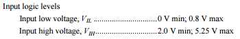
Connectors IDC 50 pin DIO and MIO are 3.3V pins, but they are 5V tolerant inputs we have protection on the IDC DIO connector. VIL values and HIV are specified in the data sheet:
http://www.NI.com/PDF/manuals/373378d.PDF
These are the recommended conditions of use. If you need to know the maximum negative voltage to determine if your landing short of the runway is acceptable, this number to an absolute minimum is - 500 mV. I would recommend you choose the appropriate to your driver series termination resistors to minimize landing short of the runway, however. The absolute minimum even applies to the 3.3V RMC DIO as well.
-
Node of devices for the control of 'ENUM '.
Hello world
I had some problems to understand the 'NumItem' property for the control to enum with property node.
I am trying to use this property to control the iterations of a 'loop' For.
Here is the related link: http://forums.ni.com/ni/board/message?board.id=170&message.id=400341&query.id=479803#M400341
Thanks for jmcbee.

the problem I have is that I did not find property 'NumItem' it, or I find some possible properties instead of him.
I be gracious, if someone of you could give me an idea.
PS: I'm using Labview 8.6.
Thanks in advance,
-Kunsheng
"NumItem" is short for "number of items". Glance for this.
-
R12.2 install on two nodes fails with validation app control
Hello
I try to install R12.2 on both nodes.
Node1 - DB level
Node2 - tier APP
Level DB install fine. Copied on node2 and used on installation of application layer configuration. "All the controls of" system to validate Configuration "going fine except 'User Apps DB connection' which shows:
User Apps DB connection
DB connection that the application was not successful. Please check the details and password login user applications.
Database connection string - jdbc:oracle:thin:@node1.my.org:1521:VIS
The database is all right, the listener up. I couldn't find all the logs that would give more verbose error statement. Nothing found on MOS... any help appriciated.
Greetings
Remigiusz biljuh
I come to rest and that Hussein will drop a suggestion that I forgot some prerequisites, or that it's a well known problem and in the meantime, I started playing with the variations of password of DB user APPS expected. I changed it to one that has my Linux user oracle, under which runs the level DB and IT... worked
My mistake.
I have provided the OS password when prompted for "Apps DB User Password", which is obviously APPS user password.
I thought to delete the entire thread, but maybe some else will hit the same problem.
Solved.
-
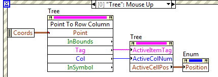
Find the element of list, table cell, node of the tree, or control by location
One of my favorite on the swing features has the opportunity to get a reference to the component UI via Container.getComponentAt (int x, int y), or a particular list item through JList.locationToIndex (Point p) (or other similar methods). I was not able to find the same or similar functionality in JFX so far... anyone can point me in the right direction?
Thank you!I don't know a way. When I started with JavaFX I had the same issue; However, I found that I actually need to do. Swing I ever need it when I was, say, treatment the mouse clicks on a JList. In JavaFX, you can register handlers with the cells directly. This does not work in the swing (in the least, not without a huge amount of effort). As well as in the swing, how to map a mouse click to a JList to the list item corresponding was to register a listener with the JList and then move the mouse click coordinates to locationToIndex (...), in JavaFX you just save the listener with the cell:
import javafx.application.Application; import javafx.event.EventHandler; import javafx.scene.Scene; import javafx.scene.control.ListCell; import javafx.scene.control.ListView; import javafx.scene.input.MouseEvent; import javafx.scene.layout.BorderPane; import javafx.stage.Stage; import javafx.util.Callback; public class ListTest extends Application { @Override public void start(Stage primaryStage) throws Exception { BorderPane root = new BorderPane(); ListViewlistView = new ListView (); listView.getItems().addAll("Apples", "Oranges", "Grapefruit", "Bananas"); listView.setCellFactory(new Callback >() { @Override public ListCell call(ListView param) { return new CustomListCell(); } }); root.setCenter(listView); Scene scene = new Scene(root, 300, 300); primaryStage.setScene(scene); primaryStage.show(); } private class CustomListCell extends ListCell { private final EventHandler listener = new EventHandler () { @Override public void handle(MouseEvent event) { System.out.printf("Mouse clicked on list cell with %s (item number %d)",getItem(), getIndex()); if (isEmpty()) { System.out.print(" (Empty cell)"); } System.out.println(); } }; private CustomListCell() { this.addEventHandler(MouseEvent.MOUSE_CLICKED, listener); } @Override public void updateItem(String item , boolean empty) { super.updateItem(item, empty); if (! empty) { setText(item); } else { setText(null); } } } public static void main(String[] args) {launch(args);} } Of course, maybe it's not your use case, and you really need this feature. Someone else can have a more direct response...

Maybe you are looking for
-
I have a problem with the icons on XP endangered.
Since the end of the support my icons disappeared and I can't what it is then a message will appear saying: cannot create association in the folder, we need to be created, so this is also something to do with my files and folder... I don't know much
-
not printed; print head alignment failed
I bought a printer HP 6700 Premium last summer (2012) and made a montage for use by WiFi connection to my laptop Dell Inspiron 1700. The printer worked fine for 2 months, he was used before packing away until may 2013. To start using again once I go
-
Windows 8 on XPS M1530 touchpad gestures?
I installed Windows 8 on my XPS M1530. Everything is good, but the gestures of scanning of Windows 8 will not work on the touchpad. I installed the driver for the Alps touchpad that worked on windows 7, but the special windows 8 gestures still do not
-
Hi all I installed WSUS 3.0 SP2 on windows server 2003, I would go for re-setup due to some problems. Before the service was running on port 8530 number then I configured all customers giving the http://server-name:8530 URL in the registry change. If
-
Large file copy fails by sensor 4240
Customer tries to copy a large file from a server in a local virtual IPS protected to a host in one vlan unprotected network IPS and the copy fails if file is greater than any 2Gbytes in size. If the server is moved to the vlan unprotected succeeds t